EP0447514B1 - Temperature measurement circuit - Google Patents
Temperature measurement circuit Download PDFInfo
- Publication number
- EP0447514B1 EP0447514B1 EP90914502A EP90914502A EP0447514B1 EP 0447514 B1 EP0447514 B1 EP 0447514B1 EP 90914502 A EP90914502 A EP 90914502A EP 90914502 A EP90914502 A EP 90914502A EP 0447514 B1 EP0447514 B1 EP 0447514B1
- Authority
- EP
- European Patent Office
- Prior art keywords
- voltage
- temperature
- terminals
- current
- measuring
- Prior art date
- Legal status (The legal status is an assumption and is not a legal conclusion. Google has not performed a legal analysis and makes no representation as to the accuracy of the status listed.)
- Expired - Lifetime
Links
- 238000009529 body temperature measurement Methods 0.000 title abstract description 6
- 239000004020 conductor Substances 0.000 claims abstract description 65
- 238000010079 rubber tapping Methods 0.000 claims abstract description 22
- 230000001419 dependent effect Effects 0.000 claims abstract description 12
- 238000011156 evaluation Methods 0.000 abstract description 24
- 238000005259 measurement Methods 0.000 description 14
- 230000007704 transition Effects 0.000 description 4
- 238000000034 method Methods 0.000 description 3
- BASFCYQUMIYNBI-UHFFFAOYSA-N platinum Chemical compound [Pt] BASFCYQUMIYNBI-UHFFFAOYSA-N 0.000 description 2
- 230000008569 process Effects 0.000 description 2
- 230000008859 change Effects 0.000 description 1
- 238000001514 detection method Methods 0.000 description 1
- 238000011161 development Methods 0.000 description 1
- 230000018109 developmental process Effects 0.000 description 1
- 230000001771 impaired effect Effects 0.000 description 1
- 229910052697 platinum Inorganic materials 0.000 description 1
- 230000009467 reduction Effects 0.000 description 1
Images
Classifications
-
- G—PHYSICS
- G01—MEASURING; TESTING
- G01K—MEASURING TEMPERATURE; MEASURING QUANTITY OF HEAT; THERMALLY-SENSITIVE ELEMENTS NOT OTHERWISE PROVIDED FOR
- G01K7/00—Measuring temperature based on the use of electric or magnetic elements directly sensitive to heat ; Power supply therefor, e.g. using thermoelectric elements
- G01K7/16—Measuring temperature based on the use of electric or magnetic elements directly sensitive to heat ; Power supply therefor, e.g. using thermoelectric elements using resistive elements
- G01K7/18—Measuring temperature based on the use of electric or magnetic elements directly sensitive to heat ; Power supply therefor, e.g. using thermoelectric elements using resistive elements the element being a linear resistance, e.g. platinum resistance thermometer
- G01K7/20—Measuring temperature based on the use of electric or magnetic elements directly sensitive to heat ; Power supply therefor, e.g. using thermoelectric elements using resistive elements the element being a linear resistance, e.g. platinum resistance thermometer in a specially-adapted circuit, e.g. bridge circuit
-
- G—PHYSICS
- G01—MEASURING; TESTING
- G01K—MEASURING TEMPERATURE; MEASURING QUANTITY OF HEAT; THERMALLY-SENSITIVE ELEMENTS NOT OTHERWISE PROVIDED FOR
- G01K1/00—Details of thermometers not specially adapted for particular types of thermometer
- G01K1/02—Means for indicating or recording specially adapted for thermometers
- G01K1/026—Means for indicating or recording specially adapted for thermometers arrangements for monitoring a plurality of temperatures, e.g. by multiplexing
Definitions
- the temperature measurement is based on the measurement of the resistance value of the temperature-dependent measuring resistor, the resistance measurement being carried out by current-voltage measurement in a four-wire circuit.
- the use of four-wire technology results in higher measuring accuracy because voltage drops caused by the current flowing through the measuring resistor at supply and transition resistances are not included in the measurement result.
- each temperature sensor is connected to the evaluation circuit by four conductors, so that the number of connecting conductors required is proportional to the number of connection conductors required for a larger number of temperature sensors, such as are often required to detect different temperatures at different points in technical systems or processes Number of temperature sensors increases and often becomes undesirably large.
- EP-A-0 187 317 describes a variant of a measuring arrangement in which resistance transducers are connected in series and with a constant current source.
- the object of the invention is to provide a temperature measuring circuit of the type specified, which, while completely retaining the advantages of four-wire technology, requires a significantly smaller number of connecting conductors between the temperature sensors and the evaluation circuit.
- the temperature measuring circuit As a result of the series connection of the temperature sensors, regardless of their number, only two current conductors are required for the connection to the current source, and the number of voltage conductors required is reduced by the fact that in each case two voltage tap terminals, two of which are connected in series consecutive temperature sensors belong to, are connected to a common voltage conductor instead of two separate voltage conductors.
- the total number of connecting conductors required is therefore only three times greater than the number of temperature sensors, compared to four times the number of temperature sensors in conventional temperature measuring circuits. As a result, the more temperature sensors are available, the greater the savings on connecting conductors.
- each common voltage conductor is not directly connected to the two associated voltage tapping terminals, but rather via resistors, ensures that the voltage measurement is carried out practically with the same accuracy as according to the conventional four-wire technique with separate voltage conductors.
- the temperature sensor 10 contains a temperature-dependent measuring resistor 11 with the resistance value R T.
- Four terminals are attached to the measuring resistor 11, namely two current connecting terminals 12, 13 and two voltage tapping terminals 14, 15, the voltage tapping terminal 14 being electrically between the current connecting terminal 12 and the measuring resistor 11 and the voltage tapping terminal 15 being electrically between the current connecting terminal 13 and the resistor 11.
- Resistance temperature sensors of this type are common known and commercially available. Platinum resistance temperature sensors of the type PT 100, which have a resistance of 100 ⁇ at 0 ° C, are widely used.
- the evaluation circuit 20 also contains a voltage measuring device 22 which is connected to the two voltage tapping terminals 14 and 15 via the conductors 18 and 19.
- the voltage measuring device 22 which is symbolically represented as a voltage meter, measures the voltage U T between the two conductors 18 and 19, which are referred to as voltage conductors.
- the temperature detected by the temperature sensor 10 can then be determined from the resistor R T.
- the resistance measurement is carried out by current-voltage measurement, and the use of four-wire technology results in higher measurement accuracy.
- the voltage between the two conductors 16 and 17 measure then the two voltage conductors 18 and 19 could be omitted, but the measured voltage would not be exactly the same as the voltage across the measuring resistor 11, but it would be about the voltage drops caused by the current I const at the supply and transition resistances, greater.
- the voltage drops at supply and transition resistances caused by the current I const have no influence on the measurement result.
- a temperature sensor In technical systems and processes, it is often necessary to record temperatures at different points using a common evaluation circuit. A temperature sensor must then be arranged at each detection point and connected to the common evaluation circuit by the necessary conductors. When using resistance temperature sensors of the type described above, which are operated in a four-wire circuit, four conductors are required for each temperature sensor, which lead to the evaluation circuit. With n temperature sensors, 4n connecting conductors are required.
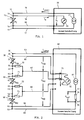
- FIG. 2 shows a temperature measuring circuit with a plurality of resistance temperature sensors of the type described and a common evaluation circuit in which the number of connecting conductors required is significantly reduced.
- the temperature sensor 30 contains one Temperature-dependent measuring resistor 31 of the resistance value R T30 with two current connection terminals 32, 33 and two voltage tapping terminals 34, 35.
- the temperature sensor 40 contains a temperature-dependent measuring resistor 41 of the resistance value R T40 with two current connection terminals 42, 43 and two voltage tapping terminals 44, 45
- the Temperature sensor 50 contains a temperature-dependent measuring resistor 51 of resistance value R T50 with two current connection terminals 52, 53 and two voltage tap terminals 54, 55.
- the evaluation circuit 60 again contains a current source 61, which supplies a constant current I const , and a voltage measuring device 62.
- the temperature sensors 30, 40 and 50 are connected in series via their current connection terminals.
- the current connection terminal 33 of the temperature sensor 30 is connected to the current connection terminal 42 of the temperature sensor 40
- the current connection terminal 43 of the temperature sensor 40 is connected to the current connection terminal 52 of the temperature sensor 50.
- the series connection of the three temperature sensors thus formed is connected to the current source 61 in the evaluation circuit 60 via two current conductors 63 and 64, which are connected to the free current connection terminals 32 and 53 of the temperature sensors 30 and 50, respectively.
- the entire arrangement therefore requires only two current conductors, regardless of the number of temperature sensors, and all measuring resistors 31, 41 and 51 are flowed through in series by the same current I const .
- the outer voltage tap terminal 34 of the temperature sensor 30 is connected to the evaluation circuit 60 via its own voltage conductor 65, and in a corresponding manner the outer voltage tap terminal 55 of the temperature sensor 50 is connected to the evaluation circuit 60 via its own voltage conductor 66.
- the two voltage taps 35 and 44, the interconnected power terminals 33 and 42 of the temperature sensors 30 and 40 are assigned to the evaluation circuit 60 via a common voltage conductor 67, and in a corresponding manner the two voltage terminals 45 and 52, which are assigned to the interconnected current connection terminals of the temperature sensors 40 and 50, are connected to the evaluation circuit 60 via a common voltage conductor 68 .
- the two voltage tapping terminals 35 and 44 are not directly connected to the common voltage conductor 67, but rather are connected via a resistor 70 and 71, respectively.
- the two voltage tapping terminals 45 and 54 are not directly connected to the common voltage conductor 68, but rather are connected via a resistor 72 and 73, respectively.
- a switching device 75 is contained in the evaluation circuit 60, by means of which the voltage measuring device 62 is optionally provided with a pair of the voltage conductors 65 , 66, 67, 68 can be connected.
- the switching device 75 is represented by mechanically adjustable switching contacts, but in reality it is of course formed from electronic switching elements, preferably in the form of a commercially available integrated circuit.
- the switching device 75 connects the voltage measuring device 62 to the two voltage conductors 65 and 67, so that the voltage U T30 is measured between these two conductors.
- the voltage measuring device 62 is connected to the two voltage conductors 67 and 68, so that it measures the voltage U T40 between these two conductors, and when the switching contacts are shifted again by one step the voltage U T50 measured between the two voltage conductors 68 and 66.
- Resistors 70 to 73 ensure that the measured voltages U T30 , U T40 , U T50 correspond with great accuracy to the voltage drops between the voltage tapping terminals of the temperature sensors 30, 40 and 50, respectively. If, for example, the resistors 70 and 71 were not provided and instead the voltage tapping terminals 35 and 44 were directly connected to the common voltage conductor 67, there would be a direct connection between the voltage tapping terminals 35 and 44 in a shunt to the connection between the current connecting terminals 33 and 42 Current I const would then be divided approximately equally between the two parallel connections, and the current component flowing through the shunt would cause voltage drops at contact resistances, which would result in a non-negligible difference between the measured voltage and the actual voltage drop at the measuring resistor.
- the series connection of the resistors 70 and 71 shunts the connection between the current connection terminals 33 and 42.
- the current component flowing through this series connection is so small that the voltage drops it causes at the transition resistances are negligible, provided that the resistance values of the resistors 70 and 71 are large compared to the total resistance of the current path via the current connection terminals 33 and 42.
- the resistance values of the resistors 70 and 71 must be small against the internal resistance of the voltage measuring device 62 so that the voltage drop caused by the measuring current flowing across the voltage conductor 67 across each of these resistors can be neglected compared to the measured voltage.
- the two aforementioned conditions for the dimensioning of the resistors 70 to 73 can easily be met, because the total resistance of the current path via the current connection terminals 33, 42 is in the range of fractions of an ohm, and the internal resistance of the voltage measuring device 62 is in the megohm range. The measurement accuracy is therefore not affected if the resistance value of each of the resistors 70 to 73 is in the order of 100 ⁇ .
- the series connection of the temperature sensors used in the temperature measuring circuit of FIG. 2 offers the possibility of an additional measure by which the current I const is not included in the measurement result, so that the measuring accuracy is not impaired by deviations or fluctuations in the current I const becomes.
- a reference resistor 76 is inserted in the current loop over which the current I const flows, which is a highly constant precision resistor of the value R ref .
- the current I const flowing through the reference resistor 76 generates a voltage drop which can be tapped as a reference voltage U ref between two voltage tap terminals 77 and 78.
- R T30 , R T40 , R T50 of the measuring resistors 31, 41, 51 then result from the ratio of the measured voltages U T30 , U T40 , U T50 to the reference voltage U ref according to the following equations:
- R T30 U T30 U ref .
- R ref R T40 U T40 U ref .
- R ref R T50 U T50 U ref .
- the voltage U ref is continuously available. If it is also queried with the aid of the switching device 75, it must be ensured, however, that the current I const does not change significantly in the time interval between the query of one of the measurement voltages U T30 , U T40 , U T50 and the query of the reference voltage U ref .
- the two resistors 70 and 71 via which the two voltage tapping terminals 35 and 44 are connected to the common voltage conductor 67, have the purpose of avoiding a direct shunt in parallel with the connection via the current connecting terminals 33 and 42. It is not absolutely necessary for this that the two resistors 70 and 71 are present; even if one of the two resistors is omitted and replaced by a direct connection, the other resistor is still shunted to the connection between the power terminals. It is therefore fundamentally possible to connect one of the two voltage terminals 35 or 44 directly to the common voltage conductor 67, provided that a resistor 70 or 71 is inserted in the connection between the other voltage terminal and the common voltage conductor. Of course, this applies correspondingly to the connections between the two voltage tapping terminals 45, 54 and the common voltage conductor 68, where one of the two resistors 72, 73 can likewise be replaced by a direct connection.
Landscapes
- Physics & Mathematics (AREA)
- General Physics & Mathematics (AREA)
- Measuring Temperature Or Quantity Of Heat (AREA)
- Measurement Of Resistance Or Impedance (AREA)
Abstract
Description
Die Erfindung betrifft eine Temperaturmeßschaltung mit mehreren Temperatursensoren, von denen jeder durch einen temperaturabhängigen Meßwiderstand mit zwei Stromanschlußklemmen und mit zwei jeweils zwischen einer zugeordneten Stromanschlußklemme und dem temperaturabhängigen Meßwiderstand angeordneten Spannungsabgriffklemme gebildet ist, und mit einer Auswerteschaltung, die über die Stromanschlußklemmen einen konstanten Strom durch jeden Temperatursensor schickt und den von dem konstanten Strom verursachten Spannungsabfall zwischen zwei mit den Spannungsabgriffklemmen verbundenen Spannungsleitern mißt.The invention relates to a temperature measuring circuit with a plurality of temperature sensors, each of which is formed by a temperature-dependent measuring resistor with two current connection terminals and with two voltage tapping terminals arranged in each case between an assigned current connection terminal and the temperature-dependent measuring resistor, and with an evaluation circuit which provides a constant current through each via the current connection terminals Temperature sensor sends and measures the voltage drop caused by the constant current between two voltage conductors connected to the voltage tap terminals.
Bei Temperaturmeßschaltungen dieser Art beruht die Temperaturmessung auf der Messung des Widerstandswertes des temperaturabhängigen Meßwiderstands, wobei die Widerstandsmessung durch Strom-Spannungs-Messung in Vierleiterschaltung erfolgt. Die Anwendung der Vierleitertechnik ergibt eine höhere Meßgenauigkeit, weil Spannungsabfälle, die der durch den Meßwiderstand fließende Strom an Zuleitungs- und Übergangswiderständen verursacht, nicht in das Meßergebnis eingehen. Als Nachteil ist anzusehen, daß jeder Temperatursensor durch vier Leiter mit der Auswerteschaltung verbunden ist, so daß bei einer größeren Anzahl von Temperatursensoren, wie sie zur Erfassung verschiedener Temperaturen an verschiedenen Stellen in technischen Anlagen oder Prozessen oft erforderlich sind, die Anzahl der benötigten Verbindungsleiter proportional zur Anzahl der Temperatursensoren ansteigt und oft unerwünscht groß wird.In temperature measuring circuits of this type, the temperature measurement is based on the measurement of the resistance value of the temperature-dependent measuring resistor, the resistance measurement being carried out by current-voltage measurement in a four-wire circuit. The use of four-wire technology results in higher measuring accuracy because voltage drops caused by the current flowing through the measuring resistor at supply and transition resistances are not included in the measurement result. As The disadvantage is that each temperature sensor is connected to the evaluation circuit by four conductors, so that the number of connecting conductors required is proportional to the number of connection conductors required for a larger number of temperature sensors, such as are often required to detect different temperatures at different points in technical systems or processes Number of temperature sensors increases and often becomes undesirably large.
EP-A-0 187 317 beschreibt eine Variante einer Meßanordnung bei welcher Widerstandsmeßwertgeber under sich und mit einer Konstantstromquelle in Reihe geschaltet sind.EP-A-0 187 317 describes a variant of a measuring arrangement in which resistance transducers are connected in series and with a constant current source.
Aufgabe der Erfindung ist die Schaffung einer Temperaturmeßschaltung der eingangs angegebenen Art, die bei völliger Beibehaltung der Vorteile der Vierleitertechnik eine wesentlich geringere Anzahl von Verbindungsleitern zwischen den Temperatursensoren und der Auswerteschaltung erfordert.The object of the invention is to provide a temperature measuring circuit of the type specified, which, while completely retaining the advantages of four-wire technology, requires a significantly smaller number of connecting conductors between the temperature sensors and the evaluation circuit.
Die Aufgabe der Erfindung wird mittels der Merkmale des Anspruchs 1 gelöst.The object of the invention is achieved by means of the features of claim 1.
Bei der Temperaturmeßschaltung nach der Erfindung werden infolge der Reihenschaltung der Temperatursensoren, unabhängig von deren Anzahl, nur zwei Stromleiter für die Verbindung mit der Stromquelle benötigt, und die Anzahl der benötigten Spannungsleiter ist dadurch verringert, daß jeweils zwei Spannungsabgriffklemmen, die zu zwei in der Reihenschaltung aufeinanderfolgenden Temperatursensoren gehören, mit einem gemeinsamen Spannungsleiter anstatt mit zwei getrennten Spannungsleitern verbunden sind. Die Anzahl der insgesamt benötigten Verbindungsleiter ist daher nur um drei größer als die Anzahl der Temperatursensoren, gegenüber dem Vierfachen der Anzahl der Temperatursensoren bei herkömmlichen Temperaturmeßschaltungen. Demzufolge ist die Einsparung an Verbindungsleitern um so größer, je mehr Temperatursensoren vorhanden sind. Dadurch, daß jeder gemeinsame Spannungsleiter mit den beiden zugeordneten Spannungsabgriffklemmen nicht direkt, sondern über Widerstände verbunden ist, ist sichergestellt, daß die Spannungsmessung praktisch mit der gleichen Genauigkeit erfolgt wie nach der herkömmlichen Vierleitertechnik mit getrennten Spannungsleitern.In the temperature measuring circuit according to the invention, as a result of the series connection of the temperature sensors, regardless of their number, only two current conductors are required for the connection to the current source, and the number of voltage conductors required is reduced by the fact that in each case two voltage tap terminals, two of which are connected in series consecutive temperature sensors belong to, are connected to a common voltage conductor instead of two separate voltage conductors. The total number of connecting conductors required is therefore only three times greater than the number of temperature sensors, compared to four times the number of temperature sensors in conventional temperature measuring circuits. As a result, the more temperature sensors are available, the greater the savings on connecting conductors. The fact that each common voltage conductor is not directly connected to the two associated voltage tapping terminals, but rather via resistors, ensures that the voltage measurement is carried out practically with the same accuracy as according to the conventional four-wire technique with separate voltage conductors.
Vorteilhafte Ausgestaltungen und Weiterbildungen der Erfindung sind in den Unteransprüchen gekennzeichnet.Advantageous refinements and developments of the invention are characterized in the subclaims.
Weitere Merkmale und Vorteile der Erfindung ergeben sich aus der folgenden Beschreibung eines Ausführungsbeispiels anhand der Zeichnung. In der Zeichnung zeigen:
- Fig. 1
- das Prinzipschema der Temperaturmessung mit einem in Vierleiterschaltung betriebenen Widerstands-Temperatursensor nach dem Stand der Technik und
- Fig. 2
- eine nach der Erfindung ausgeführte Temperaturmeßschaltung mit drei Widerstands-Temperatursensoren.
- Fig. 1
- the basic scheme of temperature measurement with a four-wire resistance temperature sensor according to the prior art and
- Fig. 2
- a designed according to the invention temperature measurement circuit with three resistance temperature sensors.
Fig. 1 zeigt schematisch das Prinzip der Temperaturmessung mittels eines in Vierleiterschaltung betriebenen Widerstands-Temperatursensors 10. Der Temperatursensor 10 enthält einen temperaturabhängigen Meßwiderstand 11 mit dem Widerstandswert RT. Am Meßwiderstand 11 sind vier Klemmen angebracht, nämlich zwei Stromanschlußklemmen 12, 13 und zwei Spannungsabgriffklemmen 14, 15, wobei die Spannungsabgriffklemme 14 elektrisch zwischen der Stromanschlußklemme 12 und dem Meßwiderstand 11 und die Spannungsabgriffklemme 15 elektrisch zwischen der Stromanschlußklemme 13 und dem Widerstand 11 liegt. Widerstands-Temperatursensoren dieser Art sind allgemein bekannt und im Handel erhältlich. Weit verbreitet sind Platin-Widerstands-Temperatursensoren des Typs PT 100, die einen Widerstand von 100 Ω bei 0°C haben.1 schematically shows the principle of temperature measurement by means of a
Die vier Klemmen 12, 13, 14 und 15 sind über vier Leiter 16, 17, 18 bzw. 19 mit einer Auswerteschaltung 20 verbunden. Die Auswerteschaltung 20 enthält eine Stromquelle 21, die über die Leiter 16 und 17 mit den beiden Stromanschlußklemmen 12 bzw. 13 verbunden ist. Sie erzeugt einen konstanten Strom Iconst, der über den Leiter 16 durch den Meßwiderstand 11 fließt und über den Leiter 17 zur Stromquelle 21 zurückkehrt. Die Leiter 16 und 17 werden deshalb als Stromleiter bezeichnet.The four
Die Auswerteschaltung 20 enthält ferner eine Spannungsmeßeinrichtung 22, die über die Leiter 18 und 19 mit den beiden Spannungsabgriffklemmen 14 und 15 verbunden ist. Die Spannungsmeßeinrichtung 22, die symbolisch als Spannungsmesser dargestellt ist, mißt die Spannung UT zwischen den beiden Leitern 18 und 19, die als Spannungsleiter bezeichnet werden.The
In der Auswerteschaltung 20 wird der temperaturabhängige Widerstandswert RT des Meßwiderstands 11 als Quotient aus dem bekannten Strom Iconst und der gemessenen Spannung UT berechnet:![]()
![]()
Aus dem Widerstand RT läßt sich dann die vom Temperatursensor 10 erfaßte Temperatur ermitteln.The temperature detected by the
Die Widerstandsmessung erfolgt also durch Strom-Spannungs-Messung, und die Anwendung der Vierleitertechnik ergibt eine höhere Meßgenauigkeit. Würde man nämlich in der Auswerteschaltung 20 die Spannung zwischen den beiden Stromleitern 16 und 17 messen, dann könnten zwar die beiden Spannungsleiter 18 und 19 entfallen, doch wäre die gemessene Spannung nicht genau gleich der Spannung am Meßwiderstand 11, sondern sie wäre um die Spannungsabfälle, die der Strom Iconst an den Zuleitungs- und Übergangswiderständen verursacht, größer. Bei Anwendung der Vierleitertechnik sind dagegen die vom Strom Iconst verursachten Spannungsabfälle an Zuleitungs- und Übergangswiderständen ohne Einfluß auf das Meßergebnis. Der über die Spannungsleiter 18, 19 fließende Meßstrom Im ist vernachlässigbar, wenn der Innenwiderstand der Spannungsmeßeinrichtung 22 groß gegen den Widerstand RT des Meßwiderstands 11 ist, was stets der Fall ist. Daher können sowohl die vom Meßstrom Im verursachten Spannungsabfälle an Zuleitungs- und Übergangswiderständen als auch die durch den Meßstrom Im bedingte Verringerung des über den Meßwiderstand 11 fließenden Stroms vernachlässigt werden.The resistance measurement is carried out by current-voltage measurement, and the use of four-wire technology results in higher measurement accuracy. Would namely namely in the
In technischen Anlagen und Prozessen ist es oft erforderlich, Temperaturen an verschiedenen Stellen mittels einer gemeinsamen Auswerteschaltung zu erfassen. An jeder Erfassungsstelle muß dann ein Temperatursensor angeordnet und durch die erforderlichen Leiter mit der gemeinsamen Auswerteschaltung verbunden werden. Bei Verwendung von Widerstands-Temperatursensoren der zuvor geschilderten Art, die in Vierleiterschaltung betrieben werden, sind dann für jeden Temperatursensor vier Leiter erforderlich, die zur Auswerteschaltung führen. Bei n Temperatursensoren sind also 4n Verbindungsleiter erforderlich.In technical systems and processes, it is often necessary to record temperatures at different points using a common evaluation circuit. A temperature sensor must then be arranged at each detection point and connected to the common evaluation circuit by the necessary conductors. When using resistance temperature sensors of the type described above, which are operated in a four-wire circuit, four conductors are required for each temperature sensor, which lead to the evaluation circuit. With n temperature sensors, 4n connecting conductors are required.
In Fig. 2 ist eine Temperaturmeßschaltung mit mehreren Widerstands-Temperatursensoren der geschilderten Art und einer gemeinsamen Auswerteschaltung dargestellt, bei der die Anzahl der erforderlichen Verbindungsleiter wesentlich verringert ist.2 shows a temperature measuring circuit with a plurality of resistance temperature sensors of the type described and a common evaluation circuit in which the number of connecting conductors required is significantly reduced.
Als Beispiel sind drei Widerstands-Temperatursensoren 30, 40 und 50 dargestellt. Der Temperatursensor 30 enthält einen temperaturabhängigen Meßwiderstand 31 des Widerstandwerts RT30 mit zwei Stromanschlußklemmen 32, 33 und zwei Spannungsabgriffklemmen 34, 35. In entsprechender Weise enthält der Temperatursensor 40 einen temperaturabhängigen Meßwiderstand 41 des Widerstandswerts RT40 mit zwei Stromanschlußklemmen 42, 43 und zwei Spannungsabgriffklemmen 44, 45, und der Temperatursensor 50 enthält einen temperaturabhängigen Meßwiderstand 51 des Widerstandswerts RT50 mit zwei Stromanschlußklemmen 52, 53 und zwei Spannungsabgriffklemmen 54, 55.As an example, three
Die Auswerteschaltung 60 enthält wieder eine Stromquelle 61, die einen konstanten Strom Iconst liefert, und eine Spannungsmeßeinrichtung 62.The
Die Temperatursensoren 30, 40 und 50 sind über ihre Stromanschlußklemmen in Reihe geschaltet. Hierzu ist die Stromanschlußklemme 33 des Temperatursensors 30 mit der Stromanschlußklemme 42 des Temperatursensors 40 verbunden, und die Stromanschlußklemme 43 des Temperatursensors 40 ist mit der Stromanschlußklemme 52 des Temperatursensors 50 verbunden. Die so gebildete Reihenschaltung der drei Temperatursensoren ist über zwei Stromleiter 63 und 64, die an die freien Stromanschlußklemmen 32 bzw. 53 der Temperatursensoren 30 bzw. 50 angeschlossen sind, mit der Stromquelle 61 in der Auswerteschaltung 60 verbunden. Die ganze Anordnung benötigt also, unabhängig von der Anzahl der Temperatursensoren, nur zwei Stromleiter, und alle Meßwiderstände 31, 41 und 51 werden von dem gleichen Strom Iconst in Reihe durchflossen.The
Die äußere Spannungsabgriffklemme 34 des Temperatursensors 30 ist über einen eigenen Spannungsleiter 65 mit der Auswerteschaltung 60 verbunden, und in entsprechender Weise ist die äußere Spannungsabgriffklemme 55 des Temperatursensors 50 über einen eigenen Spannungsleiter 66 mit der Auswerteschaltung 60 verbunden. Dagegen sind die beiden Spannungsabgriffklemmen 35 und 44, die den miteinander verbundenen Stromanschlußklemmen 33 und 42 der Temperatursensoren 30 und 40 zugeordnet sind, über einen gemeinsamen Spannungsleiter 67 mit der Auswerteschaltung 60 verbunden, und in entsprechender Weise sind die beiden Spannungsklemmen 45 und 52, die den miteinander verbunden Stromanschlußklemmen der Temperatursensoren 40 und 50 zugeordnet sind, über einen gemeinsamen Spannungsleiter 68 mit der Auswerteschaltung 60 verbunden.The outer
Die beiden Spannungsabgriffklemmen 35 und 44 sind mit dem gemeinsamen Spannungsleiter 67 nicht direkt, sondern jeweils über einen Widerstand 70 bzw. 71 verbunden. In entsprechender Weise sind die beiden Spannungsabgriffklemmen 45 und 54 mit dem gemeinsamen Spannungsleiter 68 nicht direkt, sondern jeweils über einen Widerstand 72 bzw. 73 verbunden.The two
Damit die Spannungsabfälle an den Meßwiderständen 31, 41, 51 der Temperatursensoren 30, 40, 50 von der Spannungsmeßeinrichtung 62 getrennt gemessen werden können, ist in der Auswerteschaltung 60 eine Umschaltvorrichtung 75 enthalten, durch die die Spannungsmeßeinrichtung 62 wahlweise jeweils mit einem Paar der Spannungsleiter 65, 66, 67, 68 verbunden werden kann. Zur Veranschaulichung ist die Umschaltvorrichtung 75 durch mechanisch verstellbare Schaltkontakte dargestellt, doch ist sie in Wirklichkeit natürlich aus elektronischen Schaltgliedern gebildet, vorzugsweise in Form einer im Handel erhältlichen integrierten Schaltung. Hierfür ist beispielsweise der Vierkanal-Analog-Multiplexer/Demultiplexer des Typs CD 4052 geeignet. In der in der Zeichnung dargestellten Stellung verbindet die Umschaltvorrichtung 75 die Spannungsmeßeinrichtung 62 mit den beiden Spannungsleitern 65 und 67, so daß die Spannung UT30 zwischen diesen beiden Leitern gemessen wird. Wenn die Schaltkontakte der Umschaltvorrichtung 75 um einen Schritt verschoben werden, wird die Spannungsmeßeinrichtung 62 mit den beiden Spannungsleitern 67 und 68 verbunden, so daß sie die Spannung UT40 zwischen diesen beiden Leitern mißt, und wenn die Schatkontakte nochmals um einen Schritt verschoben werden, wird die Spannung UT50 zwischen den beiden Spannungsleitern 68 und 66 gemessen.So that the voltage drops across the
Durch die Widerstände 70 bis 73 wird erreicht, daß die gemessenen Spannungen UT30, UT40, UT50 mit großer Genauigkeit den Spannungsabfällen zwischen den Spannungsabgriffklemmen der Temperatursensoren 30, 40 bzw. 50 entsprechen. Wenn beispielsweise die Widerstände 70 und 71 nicht vorgesehen wären und statt dessen die Spannungsabgriffklemmen 35 und 44 unmittelbar mit dem gemeinsamen Spannungsleiter 67 verbunden wären, bestünde eine direkte Verbindung zwischen den Spannungsabgriffklemmen 35 und 44 im Nebenschluß zu der Verbindung zwischen den Stromanschlubklemmen 33 und 42. Der Strom Iconst würde sich dann zu etwa gleichen Teilen auf die beiden parallelen Verbindungen aufteilen, und der über den Nebenschluß fließende Stromanteil würde Spannungsabfälle an Übergangswiderständen verursachen, die einen nicht vernachlässigbaren Unterschied zwischen der gemessenen Spannung und dem tatsächlichen Spannungsabfall am Meßwiderstand ergeben würden.
Bei der dargestellten Schaltung liegt dagegen die Reihenschaltung aus den Widerständen 70 und 71 im Nebenschluß zu der Verbindung zwischen den Stromanschlußklemmen 33 und 42. Der über diese Reihenschaltung fließende Stromanteil ist so klein, daß die von ihm verursachten Spannungsabfälle an Übergangswiderständen vernachlässigbar sind, vorausgesetzt, daß die Widerstandswerte der Widerstände 70 und 71 groß gegen den Gesamtwiderstand des über die Stromanschlußklemmen 33 und 42 gehenden Strompfades sind. Andererseits müssen die Widerstandswerte der Widerstände 70 und 71 klein gegen den Innenwiderstand der Spannungsmeßeinrichtung 62 sein, damit der Spannungsabfall, den der über den Spannungsleiter 67 fließende Meßstrom an jedem dieser Widerstände verursacht, gegenüber der gemessenen Spannung vernachlässigt werden kann.In the circuit shown, however, the series connection of the
Die vorstehenden Betrachtungen gelten natürlich in gleicher Weise für die Verbindung zwischen den Temperatursensoren 40 und 50 und für die Bemessung der Widerstände 72 und 73.The above considerations naturally apply in the same way to the connection between the
Die beiden zuvor genannten Bedingungen für die Bemessung der Widerstände 70 bis 73 lassen sich leicht erfüllen, denn der Gesamtwiderstand des über die Stromanschlußklemmen 33, 42 gehenden Strompfads liegt im Bereich von Bruchteilen eines Ohm, und der Innenwiderstand der Spannungsmeßeinrichtung 62 liegt im Megohmbereich. Die Meßgenauigkeit wird daher nicht beeinträchtigt, wenn der Widerstandswert jedes der Widerstände 70 bis 73 in der Größenordnung von 100 Ω liegt.The two aforementioned conditions for the dimensioning of the
Es ist daher in der Auswerteschaltung 60 möglich, die Widerstandswerte RT30, RT40 und RT50 der Meßwiderstände aus den gemessenen Spannungen UT30, UT40, UT50 nach der obigen Gleichung (1) mit großer Genauigkeit zu ermitteln, vorausgesetzt, daß auch der Strom Iconst mit entsprechender Genauigkeit bekannt ist.It is therefore possible in the
Die bei der Temperaturmeßschaltung von Fig. 2 angewendete Reihenschaltung der Temperatursensoren bietet jedoch die Möglichkeit einer zusätzlichen Maßnahme, durch die erreicht wird, daß der Strom Iconst nicht in das Meßergebnis eingeht, so daß die Meßgenauigkeit durch Abweichungen oder Schwankungen des Stroms Iconst nicht beeinträchtigt wird. Zu diesem Zweck ist in die Stromschleife, über die der Strom Iconst fließt, ein Referenzwiderstand 76 eingefügt, bei dem es sich um einen hochkonstanten Präzisionswiderstand des Wertes Rref handelt. Der über den Referenzwiderstand 76 fließende Strom Iconst erzeugt einen Spannungsabfall, der als Referenzspannung Uref zwischen zwei Spannungsabgriffklemmen 77 und 78 abgegriffen werden kann. Die Widerstandswerte RT30, RT40, RT50 der Meßwiderstände 31, 41, 51 ergeben sich dann aus dem Verhältnis der gemessenen Spannungen UT30, UT40, UT50 zur Referenzspannung Uref nach den folgenden Gleichungen:![]()
![]()
![]()
![]()
![]()
![]()
Die Spannung Uref steht dauernd zur Verfügung. Wenn sie gleichfalls mit Hilfe der Umschalteinrichtung 75 abgefragt wird, muß allerdings sichergestellt sein, daß sich der Strom Iconst im Zeitintervall zwischen der Abfrage einer der Meßspannungen UT30, UT40, UT50 und der Abfrage der Referenzspannung Uref nicht wesentlich ändert.The voltage U ref is continuously available. If it is also queried with the aid of the
Vorzugsweise ist der Widerstandswert Rref des Referenzwiderstands 76 von der gleichen Größenordnung wie die Widerstandswerte der Meßwiderstände, so daß auch die Referenzspannung Uref von der gleichen Größenordnung wie die Meßspannungen ist. Bei dem beschriebenen Beispiel hat also der Referenzwiderstand 76 beispielsweise einen Widerstandswert Rref von 100 Ω.The resistance value R ref of the
Das anhand der Temperaturmeßschaltung von Fig. 2 erläuterte Prinzip ist natürlich nicht auf die Reihenschaltung von drei Temperatursensoren beschränkt, sondern läßt sich auf eine beliebige Anzahl von Temperatursensoren erweitern. Gegenüber Temperaturmeßschaltungen, bei denen jeder Temperatursensor über vier eigene Leitungen mit der Auswerteschaltung verbunden ist, ist die Einsparung an Verbindungsleitern um so größer, je größer die Anzahl der in Reihe geschalteten Temperatursensoren ist. Bei n Temperatursensoren werden anstelle von 4n Verbindungsleitern nur n+3 Verbindungsleiter benötigt, also 3·(n-1) Verbindungsleiter eingespart. Bei der in Fig. 2 dargestellten Temperaturmeßschaltung mit n = 3 Temperatursensoren werden anstelle von 4n = 12 Verbindungsleitern nur n+3 = 6 Verbindungsleiter benötigt, so daß sechs Verbindungsleiter eingespart werden. Bei vier Temperatursensoren beträgt die Einsparung neun Verbindungsleiter usw.The principle explained on the basis of the temperature measuring circuit of FIG. 2 is of course not limited to the series connection of three temperature sensors, but can be extended to any number of temperature sensors. Compared to temperature measuring circuits, in which each temperature sensor is connected to the evaluation circuit via four separate lines, the greater the number of temperature sensors connected in series, the greater the savings on connecting conductors. With n temperature sensors, only n + 3 connecting conductors are required instead of 4n connecting conductors, So 3 · (n-1) connecting conductors saved. In the temperature measuring circuit shown in FIG. 2 with n = 3 temperature sensors, only n + 3 = 6 connecting conductors are required instead of 4n = 12 connecting conductors, so that six connecting conductors are saved. With four temperature sensors, the saving is nine connecting conductors, etc.
Wie zuvor erläutert wurde, haben die beiden Widerstände 70 und 71, über die die beiden Spannungsabgriffklemmen 35 und 44 mit dem gemeinsamen Spannungsleiter 67 verbunden sind, den Zweck, einen direkten Nebenschluß parallel zu der Verbindung über die Stromanschlußklemmen 33 und 42 zu vermeiden. Hierzu ist es nicht unbedingt erforderlich, daß die beiden Widerstände 70 und 71 vorhanden sind; auch wenn einer der beiden Widerstände fortgelassen und durch eine direkte Verbindung ersetzt wird, liegt der andere Widerstand noch im Nebenschluß zu der Verbindung zwischen den Stromanschlußklemmen. Es ist also grundsätzlich möglich, eine der beiden Spannungsklemmen 35 oder 44 direkt mit dem gemeinsamen Spannungsleiter 67 zu verbinden, vorausgesetzt, daß in die Verbindung zwischen der anderen Spannungsklemme und dem gemeinsamen Spannungsleiter ein Widerstand 70 bzw. 71 eingefügt ist. Dies gilt natürlich in entsprechender Weise für die Verbindungen zwischen den beiden Spannungsabgriffklemmen 45, 54 und dem gemeinsamen Spannungsleiter 68, wo ebenfalls einer der beiden Widerstände 72, 73 durch eine direkte Verbindung ersetzt werden kann.As previously explained, the two
Claims (3)
- Temperature measuring circuit comprising a plurality of temperature sensors, each of which is formed by a temperature-dependent measuring resistor having two current terminals and two voltage tapping terminals each arranged between an associated current terminal and the temperature-dependent measuring resistor, and an evaluating circuit which via the current terminals sends a constant current through each temperature sensor and measures the voltage drop caused by the constant current between two voltage conductors connected to the voltage tapping terminals, the temperature sensors being connected in series via the current terminals, characterized in that the two voltage tapping terminals of two temperature sensors which follow each other in the series circuit and are associated with two current terminals connected together are connected to a common voltage conductor, and that a resistor is inserted into the connection between at least one of the two voltage tapping terminals and the common voltage conductor.
- Temperature measuring circuit according to claim 1, characterized in that a constant reference resistor of known magnitude is connected in series with the temperature sensors in such a manner that it is traversed by the constant current and that the voltage drop caused by the constant current across the reference resistor is used in the evaluating circuit as reference voltage for determining the resistance value of each measuring resistor.
- Temperature measuring circuit according to claim 1 or 2, characterized in that the evaluating circuit includes a voltage measuring means and a switchover means for connecting the voltage measuring means in each case to two voltage connectors connected to the same temperature sensor.
Applications Claiming Priority (2)
| Application Number | Priority Date | Filing Date | Title |
|---|---|---|---|
| DE3933311 | 1989-10-05 | ||
| DE3933311A DE3933311A1 (en) | 1989-10-05 | 1989-10-05 | TEMPERATURE MEASURING |
Publications (2)
| Publication Number | Publication Date |
|---|---|
| EP0447514A1 EP0447514A1 (en) | 1991-09-25 |
| EP0447514B1 true EP0447514B1 (en) | 1993-09-22 |
Family
ID=6390902
Family Applications (1)
| Application Number | Title | Priority Date | Filing Date |
|---|---|---|---|
| EP90914502A Expired - Lifetime EP0447514B1 (en) | 1989-10-05 | 1990-10-05 | Temperature measurement circuit |
Country Status (5)
| Country | Link |
|---|---|
| US (1) | US5171091A (en) |
| EP (1) | EP0447514B1 (en) |
| JP (1) | JPH03504048A (en) |
| DE (2) | DE3933311A1 (en) |
| WO (1) | WO1991005229A1 (en) |
Cited By (1)
| Publication number | Priority date | Publication date | Assignee | Title |
|---|---|---|---|---|
| DE4445243A1 (en) * | 1993-12-27 | 1995-06-29 | Ngk Insulators Ltd | Temperature sensor |
Families Citing this family (23)
| Publication number | Priority date | Publication date | Assignee | Title |
|---|---|---|---|---|
| US5317520A (en) * | 1991-07-01 | 1994-05-31 | Moore Industries International Inc. | Computerized remote resistance measurement system with fault detection |
| AT397311B (en) * | 1991-08-16 | 1994-03-25 | Hans Dr Leopold | METHOD FOR DETERMINING A MEASURED VALUE AND CIRCUIT ARRANGEMENT FOR IMPLEMENTING THE METHOD |
| US5435308A (en) * | 1992-07-16 | 1995-07-25 | Abbott Laboratories | Multi-purpose multi-parameter cardiac catheter |
| EP0622733B1 (en) * | 1993-04-30 | 1997-07-16 | STMicroelectronics S.r.l. | Method and device for testing integrated power devices |
| DE4411428A1 (en) * | 1994-03-31 | 1995-10-05 | Bayerische Motoren Werke Ag | Measuring device for determining two physical parameters |
| DE4442457A1 (en) * | 1994-11-29 | 1996-05-30 | Bayerische Motoren Werke Ag | Electronic temperature measurement using hermetically sealed reference resistor |
| US5775809A (en) * | 1996-07-11 | 1998-07-07 | Measurement Dynamics Llc | Vehicle compartment temperature recorder |
| US5902044A (en) * | 1997-06-27 | 1999-05-11 | International Business Machines Corporation | Integrated hot spot detector for design, analysis, and control |
| US5929344A (en) * | 1997-07-28 | 1999-07-27 | Micro Motion, Inc. | Circuitry for reducing the number of conductors for multiple resistive sensors on a coriolis effect mass flowmeter |
| US6651020B2 (en) * | 1997-12-24 | 2003-11-18 | Edward S. More | Method and apparatus for economical drift compensation in high resolution measurements |
| US6334093B1 (en) * | 1997-12-24 | 2001-12-25 | Edward S. More | Method and apparatus for economical drift compensation in high resolution difference measurements and exemplary low cost, high resolution differential digital thermometer |
| US6786639B2 (en) * | 2002-08-30 | 2004-09-07 | International Business Machines Corporation | Device for sensing temperature of an electronic chip |
| DE102004009267B3 (en) * | 2004-02-26 | 2005-09-22 | Siemens Ag | Selection arrangement for magneto-resistive component, has regulated voltage source to generate offset voltage in output branch for adjusting signal hub of magneto-resistive component |
| DE102005029045A1 (en) * | 2005-06-21 | 2007-01-04 | Endress + Hauser Wetzer Gmbh + Co Kg | Apparatus and method for determining and / or monitoring the temperature |
| US7412347B2 (en) * | 2006-01-23 | 2008-08-12 | Sherwood Engineering Design Services, Inc. | Method and apparatus for measuring physical parameters |
| US7896545B2 (en) * | 2008-03-19 | 2011-03-01 | Micron Technology, Inc. | Apparatus and methods for temperature calibration and sensing |
| US8408787B2 (en) * | 2009-01-09 | 2013-04-02 | Rosemount Inc. | Process temperature transmitter with improved temperature calculation |
| DE102012208125A1 (en) * | 2012-05-15 | 2013-11-21 | E.G.O. Elektro-Gerätebau GmbH | Temperature measuring device, electrical device with such a temperature measuring device and method for temperature measurement |
| CN103033278B (en) * | 2012-12-26 | 2015-07-29 | 重庆川仪自动化股份有限公司 | Integrative temperature transmitter |
| DE102013211058B3 (en) * | 2013-06-13 | 2014-10-23 | Lisa Dräxlmaier GmbH | Current contact pliers for a four-wire measurement in the range of high voltage and high current |
| US10591531B2 (en) * | 2015-06-10 | 2020-03-17 | Qualcomm Incorporated | Method and apparatus for integrated circuit monitoring and prevention of electromigration failure |
| US20180254644A1 (en) * | 2017-03-06 | 2018-09-06 | Intel Corporation | Techniques for charger control |
| DE102017130135A1 (en) | 2017-12-15 | 2019-06-19 | Endress + Hauser Wetzer Gmbh + Co. Kg | Condition monitoring of a temperature sensor |
Family Cites Families (10)
| Publication number | Priority date | Publication date | Assignee | Title |
|---|---|---|---|---|
| JPS526677B1 (en) * | 1969-10-01 | 1977-02-23 | ||
| DE2526027A1 (en) * | 1975-06-11 | 1976-12-23 | Hartmann & Braun Ag | Refrigerator plant temp. difference monitor - provides multipoint direct measurement of temp. differences as current differences to accuracy of tenth of degree C |
| DD206176A3 (en) * | 1981-04-22 | 1984-01-18 | METHOD AND CIRCUIT ARRANGEMENT FOR TEMPERATURE MEASUREMENT | |
| JPS58429A (en) * | 1981-06-20 | 1983-01-05 | Kyokuto Kaihatsu Kogyo Co Ltd | Three way dump truck |
| EP0120102A1 (en) * | 1983-03-23 | 1984-10-03 | Firma Carl Zeiss | Temperature measuring device |
| DE3572861D1 (en) * | 1985-01-03 | 1989-10-12 | Siemens Ag | Measuring equipment with resistance measurement transducer |
| JPS61223622A (en) * | 1985-03-29 | 1986-10-04 | Toshiba Corp | Multitemperature measuring instrument |
| US4699519A (en) * | 1985-04-08 | 1987-10-13 | Performance Technology, Inc. | Grain temperature monitor |
| SU1352243A1 (en) * | 1985-12-02 | 1987-11-15 | Предприятие П/Я А-7445 | Multichannel temperature measuring device |
| DE3701082A1 (en) * | 1987-01-16 | 1988-07-28 | Ziegler Horst | DEVICE FOR REMOTE MEASUREMENT OF THE TEMPERATURE |
-
1989
- 1989-10-05 DE DE3933311A patent/DE3933311A1/en active Granted
-
1990
- 1990-10-05 WO PCT/DE1990/000762 patent/WO1991005229A1/en not_active Ceased
- 1990-10-05 EP EP90914502A patent/EP0447514B1/en not_active Expired - Lifetime
- 1990-10-05 JP JP2513533A patent/JPH03504048A/en active Pending
- 1990-10-05 DE DE90914502T patent/DE59002854D1/en not_active Expired - Fee Related
- 1990-10-05 US US07/687,863 patent/US5171091A/en not_active Expired - Fee Related
Cited By (3)
| Publication number | Priority date | Publication date | Assignee | Title |
|---|---|---|---|---|
| DE4445243A1 (en) * | 1993-12-27 | 1995-06-29 | Ngk Insulators Ltd | Temperature sensor |
| US5823680A (en) * | 1993-12-27 | 1998-10-20 | Ngk Insulators, Ltd. | Temperature sensor |
| DE4445243C2 (en) * | 1993-12-27 | 2002-03-21 | Ngk Insulators Ltd | temperature sensor |
Also Published As
| Publication number | Publication date |
|---|---|
| EP0447514A1 (en) | 1991-09-25 |
| DE3933311A1 (en) | 1991-04-18 |
| US5171091A (en) | 1992-12-15 |
| DE59002854D1 (en) | 1993-10-28 |
| JPH03504048A (en) | 1991-09-05 |
| DE3933311C2 (en) | 1992-03-26 |
| WO1991005229A1 (en) | 1991-04-18 |
Similar Documents
| Publication | Publication Date | Title |
|---|---|---|
| EP0447514B1 (en) | Temperature measurement circuit | |
| EP2981833B1 (en) | Measuring resistor and corresponding measuring method | |
| EP2880410B1 (en) | Multiwire measuring device for detecting a defective, temperature-dependent resistance sensor | |
| DE102004056133B4 (en) | Method for detecting an offset drift in a Wheatstone measuring bridge | |
| EP1431768B1 (en) | Method and Device for Resistance Measurement of a Temperature Dependent Resistor | |
| EP0203350A2 (en) | Temperature measuring device to measure big changes in temperature | |
| EP0612412B1 (en) | Polarity testing process and device for electrolytic capacitors | |
| EP0016409B1 (en) | Apparatus to measure temperature and a temperature differential almost simultaneously | |
| DE2531784C2 (en) | Measuring arrangement for temperature and pressure measurement of a medium in boreholes | |
| WO2004106866A2 (en) | Method and circuit arrangement for detecting the level of a liquid | |
| DE19531386C2 (en) | Evaluation circuit for a thick film pressure sensor | |
| DE3344363C2 (en) | ||
| DE2141361B2 (en) | ||
| DE3634053A1 (en) | Method and circuit arrangement for measuring the resistance values of two series-connected sensor resistors | |
| DE4040332C2 (en) | Multi-electrode stray field method for measuring the electrolytic conductivity of a liquid as well as a multi-electrode stray field sensor | |
| EP1962070B1 (en) | High temperature sensor and test method therefor | |
| DE2162040C3 (en) | Circuit arrangement for detecting line short-circuits | |
| DE3731012C2 (en) | Ignition circuit tester with constant climate display | |
| DE2318520C2 (en) | Circuit arrangement with a resistor smeBwertgeber | |
| EP1870701B1 (en) | Assembly for detecting air components | |
| DE1103458B (en) | Directly displaying ohmmeter with switchable measuring ranges | |
| EP0877238A1 (en) | Measuring device with multiple input channels | |
| DE3032948A1 (en) | Ohmmeter with high and low ranges - uses measurement resistance changeover, divider, and high range potential divider | |
| DE1113748B (en) | Direct reading ohmmeter | |
| DE4428689A1 (en) | Four-line circuit operation method for resistance thermometer |
Legal Events
| Date | Code | Title | Description |
|---|---|---|---|
| PUAI | Public reference made under article 153(3) epc to a published international application that has entered the european phase |
Free format text: ORIGINAL CODE: 0009012 |
|
| 17P | Request for examination filed |
Effective date: 19910524 |
|
| AK | Designated contracting states |
Kind code of ref document: A1 Designated state(s): CH DE FR GB IT LI SE |
|
| 17Q | First examination report despatched |
Effective date: 19930218 |
|
| GRAA | (expected) grant |
Free format text: ORIGINAL CODE: 0009210 |
|
| AK | Designated contracting states |
Kind code of ref document: B1 Designated state(s): CH DE FR GB IT LI SE |
|
| ITF | It: translation for a ep patent filed | ||
| REF | Corresponds to: |
Ref document number: 59002854 Country of ref document: DE Date of ref document: 19931028 |
|
| ET | Fr: translation filed | ||
| GBT | Gb: translation of ep patent filed (gb section 77(6)(a)/1977) |
Effective date: 19940106 |
|
| PLBE | No opposition filed within time limit |
Free format text: ORIGINAL CODE: 0009261 |
|
| STAA | Information on the status of an ep patent application or granted ep patent |
Free format text: STATUS: NO OPPOSITION FILED WITHIN TIME LIMIT |
|
| 26N | No opposition filed | ||
| EAL | Se: european patent in force in sweden |
Ref document number: 90914502.1 |
|
| PGFP | Annual fee paid to national office [announced via postgrant information from national office to epo] |
Ref country code: CH Payment date: 19990915 Year of fee payment: 10 |
|
| PGFP | Annual fee paid to national office [announced via postgrant information from national office to epo] |
Ref country code: SE Payment date: 19990920 Year of fee payment: 10 |
|
| PG25 | Lapsed in a contracting state [announced via postgrant information from national office to epo] |
Ref country code: SE Free format text: THE PATENT HAS BEEN ANNULLED BY A DECISION OF A NATIONAL AUTHORITY Effective date: 20001030 |
|
| PG25 | Lapsed in a contracting state [announced via postgrant information from national office to epo] |
Ref country code: LI Free format text: LAPSE BECAUSE OF NON-PAYMENT OF DUE FEES Effective date: 20001031 Ref country code: CH Free format text: LAPSE BECAUSE OF NON-PAYMENT OF DUE FEES Effective date: 20001031 |
|
| REG | Reference to a national code |
Ref country code: CH Ref legal event code: PL |
|
| EUG | Se: european patent has lapsed |
Ref document number: 90914502.1 |
|
| REG | Reference to a national code |
Ref country code: GB Ref legal event code: IF02 |
|
| PGFP | Annual fee paid to national office [announced via postgrant information from national office to epo] |
Ref country code: GB Payment date: 20030929 Year of fee payment: 14 |
|
| PGFP | Annual fee paid to national office [announced via postgrant information from national office to epo] |
Ref country code: FR Payment date: 20031009 Year of fee payment: 14 |
|
| PGFP | Annual fee paid to national office [announced via postgrant information from national office to epo] |
Ref country code: DE Payment date: 20031010 Year of fee payment: 14 |
|
| PG25 | Lapsed in a contracting state [announced via postgrant information from national office to epo] |
Ref country code: GB Free format text: LAPSE BECAUSE OF NON-PAYMENT OF DUE FEES Effective date: 20041005 |
|
| PG25 | Lapsed in a contracting state [announced via postgrant information from national office to epo] |
Ref country code: DE Free format text: LAPSE BECAUSE OF NON-PAYMENT OF DUE FEES Effective date: 20050503 |
|
| GBPC | Gb: european patent ceased through non-payment of renewal fee |
Effective date: 20041005 |
|
| PG25 | Lapsed in a contracting state [announced via postgrant information from national office to epo] |
Ref country code: FR Free format text: LAPSE BECAUSE OF NON-PAYMENT OF DUE FEES Effective date: 20050630 |
|
| REG | Reference to a national code |
Ref country code: FR Ref legal event code: ST |
|
| PG25 | Lapsed in a contracting state [announced via postgrant information from national office to epo] |
Ref country code: IT Free format text: LAPSE BECAUSE OF NON-PAYMENT OF DUE FEES;WARNING: LAPSES OF ITALIAN PATENTS WITH EFFECTIVE DATE BEFORE 2007 MAY HAVE OCCURRED AT ANY TIME BEFORE 2007. THE CORRECT EFFECTIVE DATE MAY BE DIFFERENT FROM THE ONE RECORDED. Effective date: 20051005 |