EP0447510B1 - Antriebssystem für kraftfahrzeuge und kraftfahrzeug mit einem solchen antriebssystem - Google Patents
Antriebssystem für kraftfahrzeuge und kraftfahrzeug mit einem solchen antriebssystem Download PDFInfo
- Publication number
- EP0447510B1 EP0447510B1 EP90914059A EP90914059A EP0447510B1 EP 0447510 B1 EP0447510 B1 EP 0447510B1 EP 90914059 A EP90914059 A EP 90914059A EP 90914059 A EP90914059 A EP 90914059A EP 0447510 B1 EP0447510 B1 EP 0447510B1
- Authority
- EP
- European Patent Office
- Prior art keywords
- hydromotor
- pressure
- hydraulic
- hydraulic motor
- braking
- Prior art date
- Legal status (The legal status is an assumption and is not a legal conclusion. Google has not performed a legal analysis and makes no representation as to the accuracy of the status listed.)
- Expired - Lifetime
Links
Images


Classifications
-
- F—MECHANICAL ENGINEERING; LIGHTING; HEATING; WEAPONS; BLASTING
- F16—ENGINEERING ELEMENTS AND UNITS; GENERAL MEASURES FOR PRODUCING AND MAINTAINING EFFECTIVE FUNCTIONING OF MACHINES OR INSTALLATIONS; THERMAL INSULATION IN GENERAL
- F16H—GEARING
- F16H61/00—Control functions within control units of change-speed- or reversing-gearings for conveying rotary motion ; Control of exclusively fluid gearing, friction gearing, gearings with endless flexible members or other particular types of gearing
- F16H61/38—Control of exclusively fluid gearing
- F16H61/40—Control of exclusively fluid gearing hydrostatic
- F16H61/4157—Control of braking, e.g. preventing pump over-speeding when motor acts as a pump
-
- B—PERFORMING OPERATIONS; TRANSPORTING
- B60—VEHICLES IN GENERAL
- B60K—ARRANGEMENT OR MOUNTING OF PROPULSION UNITS OR OF TRANSMISSIONS IN VEHICLES; ARRANGEMENT OR MOUNTING OF PLURAL DIVERSE PRIME-MOVERS IN VEHICLES; AUXILIARY DRIVES FOR VEHICLES; INSTRUMENTATION OR DASHBOARDS FOR VEHICLES; ARRANGEMENTS IN CONNECTION WITH COOLING, AIR INTAKE, GAS EXHAUST OR FUEL SUPPLY OF PROPULSION UNITS IN VEHICLES
- B60K6/00—Arrangement or mounting of plural diverse prime-movers for mutual or common propulsion, e.g. hybrid propulsion systems comprising electric motors and internal combustion engines
- B60K6/08—Prime-movers comprising combustion engines and mechanical or fluid energy storing means
- B60K6/12—Prime-movers comprising combustion engines and mechanical or fluid energy storing means by means of a chargeable fluidic accumulator
-
- B—PERFORMING OPERATIONS; TRANSPORTING
- B60—VEHICLES IN GENERAL
- B60T—VEHICLE BRAKE CONTROL SYSTEMS OR PARTS THEREOF; BRAKE CONTROL SYSTEMS OR PARTS THEREOF, IN GENERAL; ARRANGEMENT OF BRAKING ELEMENTS ON VEHICLES IN GENERAL; PORTABLE DEVICES FOR PREVENTING UNWANTED MOVEMENT OF VEHICLES; VEHICLE MODIFICATIONS TO FACILITATE COOLING OF BRAKES
- B60T1/00—Arrangements of braking elements, i.e. of those parts where braking effect occurs specially for vehicles
- B60T1/02—Arrangements of braking elements, i.e. of those parts where braking effect occurs specially for vehicles acting by retarding wheels
- B60T1/10—Arrangements of braking elements, i.e. of those parts where braking effect occurs specially for vehicles acting by retarding wheels by utilising wheel movement for accumulating energy, e.g. driving air compressors
-
- F—MECHANICAL ENGINEERING; LIGHTING; HEATING; WEAPONS; BLASTING
- F16—ENGINEERING ELEMENTS AND UNITS; GENERAL MEASURES FOR PRODUCING AND MAINTAINING EFFECTIVE FUNCTIONING OF MACHINES OR INSTALLATIONS; THERMAL INSULATION IN GENERAL
- F16H—GEARING
- F16H61/00—Control functions within control units of change-speed- or reversing-gearings for conveying rotary motion ; Control of exclusively fluid gearing, friction gearing, gearings with endless flexible members or other particular types of gearing
- F16H61/38—Control of exclusively fluid gearing
- F16H61/40—Control of exclusively fluid gearing hydrostatic
- F16H61/4078—Fluid exchange between hydrostatic circuits and external sources or consumers
- F16H61/4096—Fluid exchange between hydrostatic circuits and external sources or consumers with pressure accumulators
-
- F—MECHANICAL ENGINEERING; LIGHTING; HEATING; WEAPONS; BLASTING
- F16—ENGINEERING ELEMENTS AND UNITS; GENERAL MEASURES FOR PRODUCING AND MAINTAINING EFFECTIVE FUNCTIONING OF MACHINES OR INSTALLATIONS; THERMAL INSULATION IN GENERAL
- F16H—GEARING
- F16H61/00—Control functions within control units of change-speed- or reversing-gearings for conveying rotary motion ; Control of exclusively fluid gearing, friction gearing, gearings with endless flexible members or other particular types of gearing
- F16H61/38—Control of exclusively fluid gearing
- F16H61/40—Control of exclusively fluid gearing hydrostatic
- F16H61/4148—Open loop circuits
-
- F—MECHANICAL ENGINEERING; LIGHTING; HEATING; WEAPONS; BLASTING
- F16—ENGINEERING ELEMENTS AND UNITS; GENERAL MEASURES FOR PRODUCING AND MAINTAINING EFFECTIVE FUNCTIONING OF MACHINES OR INSTALLATIONS; THERMAL INSULATION IN GENERAL
- F16H—GEARING
- F16H61/00—Control functions within control units of change-speed- or reversing-gearings for conveying rotary motion ; Control of exclusively fluid gearing, friction gearing, gearings with endless flexible members or other particular types of gearing
- F16H61/38—Control of exclusively fluid gearing
- F16H61/40—Control of exclusively fluid gearing hydrostatic
- F16H61/4165—Control of cooling or lubricating
-
- B—PERFORMING OPERATIONS; TRANSPORTING
- B60—VEHICLES IN GENERAL
- B60T—VEHICLE BRAKE CONTROL SYSTEMS OR PARTS THEREOF; BRAKE CONTROL SYSTEMS OR PARTS THEREOF, IN GENERAL; ARRANGEMENT OF BRAKING ELEMENTS ON VEHICLES IN GENERAL; PORTABLE DEVICES FOR PREVENTING UNWANTED MOVEMENT OF VEHICLES; VEHICLE MODIFICATIONS TO FACILITATE COOLING OF BRAKES
- B60T2270/00—Further aspects of brake control systems not otherwise provided for
- B60T2270/60—Regenerative braking
- B60T2270/602—ABS features related thereto
-
- Y—GENERAL TAGGING OF NEW TECHNOLOGICAL DEVELOPMENTS; GENERAL TAGGING OF CROSS-SECTIONAL TECHNOLOGIES SPANNING OVER SEVERAL SECTIONS OF THE IPC; TECHNICAL SUBJECTS COVERED BY FORMER USPC CROSS-REFERENCE ART COLLECTIONS [XRACs] AND DIGESTS
- Y02—TECHNOLOGIES OR APPLICATIONS FOR MITIGATION OR ADAPTATION AGAINST CLIMATE CHANGE
- Y02T—CLIMATE CHANGE MITIGATION TECHNOLOGIES RELATED TO TRANSPORTATION
- Y02T10/00—Road transport of goods or passengers
- Y02T10/60—Other road transportation technologies with climate change mitigation effect
- Y02T10/62—Hybrid vehicles
Definitions
- the invention relates to a drive system for motor vehicles, at least one hydrostatic hydraulic motor being provided for driving at least two wheels on at least one axle, which is driven by at least one pump driven by an internal combustion engine and / or an electric motor via an intermediate pressure accumulator with hydraulic fluid ,
- the braking energy generated when braking the vehicle can be used via the hydraulic motor acting as a pump to charge the pressure accumulator and the drive connection from the internal combustion engine and / or electric motor to the wheels of the motor vehicle takes place exclusively by hydraulic means
- the hydraulic motor also having one of externally adjustable swashplate or swivel plate and is connected to the pressure accumulator in a direct two-way connection, the high-pressure side of the hydraulic motor both when accelerating and when braking the motor vehicle euges is always arranged on the same hydraulic connection of the hydraulic motor.
- the hydraulic motor in braking mode, supplies a feed pump circuit formed from a feed pump together with an associated preload valve for the delivery of hydraulic oil from the pressureless reservoir;
- a check valve upstream of the hydraulic motor ensures that hydraulic oil is shut off from the hydraulic motor in a leak-free manner during the idle and idle operating phases.
- the drive system is designed as a four-wheel drive, so that for each of the vehicle wheels in a manner known per se, a separate, connected hydraulic motor is provided, and that signals are given per wheel by sensors or control elements in a manner known per se of a computer can be implemented in correspondingly different or the same inclined positions of the individual swash plates.
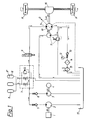
- FIG. 1 shows the circuit diagram for a drive system according to the invention for an axle of a motor vehicle in the starting or acceleration phase
- FIG. 2 shows an illustration similar to that in FIG. 1 but now in the freewheeling or idling phase
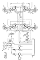
- FIG. 4 the circuit diagram similar to that in FIG. 1 for a four-wheel drive in the starting or acceleration phase
- FIG. 5 but an analog representation as FIG. 4 now in the freewheeling or idling phase
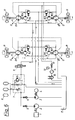
- FIG. 6 an analogous representation as in FIG. 4 but now in the braking or deceleration phase.
- FIG. 1-3 show an embodiment of the drive system for motor vehicles according to the invention, wherein an adjustable, hydrostatic hydraulic motor 10 drives two driven wheels R arranged on an axis in a conventional manner via a cardan shaft and a differential gear 16.
- the ⁇ -shaped symbol in the shaft leading from the hydraulic motor 10 to the differential gear 16 denotes a mechanical drive connection which can have elastic or cardanic properties;
- the same symbols are used in all figures for all such drive connections, e.g. used between the internal combustion engine 1 and the hydraulic (main) pump 2 for the hydraulic fluid.
- the internal combustion engine 1 and the (main) pump 2 for the hydraulic fluid or the hydraulic oil stand still; if at first the first auxiliary drive 3, e.g., not required for the basic function of the drive system, e.g. If a solar drive consisting of a solar cell and an electric motor 4 with the first auxiliary pump 3 mechanically coupled therewith is assumed to be absent, the pressure accumulator 8 would initially be depressurized.
- the internal combustion engine 1 must therefore first be started in order to convey pressure fluid from the pressureless reservoir 17 via the pump 2, the check valve 5 and the accumulator safety block 7 into the accumulator 8. As soon as the pressure accumulator 8 has the required pressure, which is, for example, of the order of 200-400 bar, the motor vehicle can be set in motion.
- the motor vehicle can be set in motion without having to start the internal combustion engine 1 beforehand. Starting or starting and stopping the internal combustion engine 1 expediently takes place automatically in driving operation as a function of the pressure in the pressure accumulator 8.
- the drive system according to the invention offers the advantage of being problem-free Connection of any number of auxiliary drives parallel to the main drive 1,2 (therefore “first” auxiliary pump 3 or “first” auxiliary drive 4).
- the memory security block 7 is a commercially available structural unit, the use of which is prescribed in connection with pressure accumulators. In the order from left to right in Fig. 1, this block 7 comprises manually operable valves for the inlet to the reservoir 8, for emptying the reservoir 8 into the reservoir 17 and a pressure relief or pressure relief valve with overflow into the reservoir 17. Der Connection provided with a double arrow on block 7 is used to check or display the storage pressure and / or to connect additional storage.
- the energy accumulator or hydraulic accumulator or pressure accumulator 8 is a component known per se which consists of a pressure-resistant container which is made up of a flexible membrane, a piston, a rubber bladder or the like. is divided into two pressure-tight compartments 8 ', 8' ', of which the compartment 8' with the pressurized liquid and the compartment 8 '' with a gas, e.g. Nitrogen, is filled.
- a gas e.g. Nitrogen
- the check valve 9 is magnetically unlocked when the accelerator pedal (not shown) is depressed and the path to the hydraulic motor 10 is released to the hydraulic fluid.
- the adjustment of the swash plate or swash plate of the hydraulic motor 10 indicated by the arrow symbol in the hydraulic motor 10 is carried out by the accelerator pedal in the range from 0 to A for the acceleration phase depending on the torque required or desired on the wheels.
- a conventional operative connection (electrical, mechanical or the like), not shown, is provided between the accelerator pedal and the swivel plate control.
- Such an adjustable hydraulic motor 10 is also referred to as a hydrostatic hydraulic motor with secondary control.
- the check valve 9 is therefore provided in order to shut off the pressure fluid inlet without leakage when the vehicle is stationary; any leakage liquid is over the Dashed line discharged from the hydraulic motor 10 directly into the reservoir 17.
- Another circuit of the pressure fluid runs from the reservoir 17 via the feed pump mechanically driven by the hydraulic motor 10 together with the preload valve, which two components are identified as a unit with reference number 11.
- This feed pump circuit 11 eliminates any problems that may occur due to the suction behavior (in the deceleration phase, see FIG. 3) of the hydraulic motor 10 and is also known per se from industrial hydraulics.
- the feed pump 11 delivers a slightly larger amount of hydraulic fluid than the stroke volume of the hydraulic motor 10, and thus ensures the supply operation of the hydraulic motor 10 in the deceleration phase by providing and maintaining a certain basic pressure or supply pressure at the reservoir-side connection of the hydraulic motor 10
- Feed pump circuit 11 can be set to a somewhat higher pressure than valve 13.
- the hydraulic fluid delivered by the feed pump 11 is not required by the hydraulic motor and returns to the reservoir 17 via the elements 13, 14, 15.
- the flow path of the hydraulic fluid is indicated by arrows.
- FIG. 2 shows the drive system according to the invention according to FIG. 1 in the free-running phase.
- the arrow symbol remains in the 0 position and accordingly the swash plate of the hydraulic motor 10 is in its straight neutral position, so that the hydraulic motor 10 acts neither as a motor nor as a pump.
- the accelerator pedal of the motor vehicle is in the rest position and therefore the check valve 9 is closed and locked.
- Feed pump circuit 11 works in the same way as in the acceleration phase, since the feed pump continues to be mechanically driven by the wheels R of the free-running motor vehicle via the hydraulic motor 10, which is also free-running.
- the feed pump in the feed circuit 11 no longer works only when the motor vehicle is at a standstill.
- FIG. 3 shows the drive system according to the invention according to FIG. 1 in the deceleration phase.
- the swash plate of the hydraulic motor 10 (arrow symbol in FIG. 3) which is operatively connected to the brake pedal of the motor vehicle in the adjustment range from 0 to B is adjusted so that the hydraulic motor 10 is now driven by the pump of the motor vehicle, which continues to rotate in the same direction as before acts for the hydraulic fluid, the latter being sucked out of the supply circuit 11 and fed back via the valve 9 into the pressure accumulator 8 until it is fully charged.
- the pressure fluid is discharged into the reservoir 17 via the pressure limiting valve in the storage safety block 7.
- FIG. 4 shows the circuit diagram of the drive system according to the invention for a four-wheel drive in an analogous representation to FIG. 1, each wheel R being driven by its own, jointly or independently adjustable, hydraulic motor 10.1, 10.2, 10.3 and 10.4.
- Each of these hydraulic motors is assigned its own feed circuit 11.1, 11.2, 11.3, 11.4, which, as in the case of FIGS. 1-3, consists of a feed pump with a preload valve.
- the other components are the same as those in Fig. 1-3, the operation is also the same.
- a computer must be interposed between the accelerator pedal and the control devices of the swash plates of the individual hydraulic motors 10.1, 10.2, 10.3, 10.4, which computer converts the signals given by known sensors or control elements into different or identical inclined positions of the individual swash plates.
- an essential aspect of the drive system is the independence of the wheels of the motor vehicle driving output motor (hydraulic motor 10 or 10.1, 10.2, 10.3, 10.4) and the transmitted energy from the energy generated by the internal combustion engine 1 or other drive sources 4 at the same time. This independence is achieved by the interposition of a pressure accumulator 8 which acts as an intermediate buffer.
- Another essential aspect of the drive system according to the invention is the almost complete utilization of the braking energy.
- the hydrostatics therefore do not serve as a replacement for a mechanical transmission (as is known in principle) (the basic characteristic of which is to transmit power generated by the internal combustion engine directly to the wheels in different gear ratios), but first of all draws the energy from various Drive sources 1-4 and stores them in the pressure accumulators 8 or hydraulic accumulators.
- This energy storage system has the additional advantage that it can provide considerably more power than that from the internal combustion engine 1 for short periods of time (acceleration). This is also a difference from today's common drive systems, in which at most the power of the internal combustion engine 1 is available.
- the braking energy is used to charge the accumulators 8 as an energy source, which is not converted into heat by friction linings as is the case in conventional braking systems or is destroyed as mechanical energy via the (combustion) engine brake.
- the vibrational energy of the vehicle is recovered to a considerable extent by operating the hydraulic motor 10 as a generator and stored in the hydraulic accumulator or pressure accumulator 8.
- the internal combustion engine 1 therefore only has to generate the missing energy (differential energy due to efficiency losses).
- the internal combustion engine 1 starts and fills the energy or pressure accumulator 8 continuously at low speed via the hydraulic pump 2.
- the energy accumulator 8 is completely or partially filled, the driving operation can begin.
- the memory 8 can of course already be filled by a previous braking process or the solar drive 4; then you can start driving without having to start the internal combustion engine 1 beforehand.
- the energy from the pressure accumulator 8 is now available for acceleration and the swivel disk of the hydraulic motor 10 is adjusted to the side A (FIGS. 1 and 4). Depending on the adjustment, the desired drive (acceleration) torque is available.
- the "freewheeling" operating phase can be started, the swivel disk of the hydraulic motor 10 being in the neutral center position 0 (FIGS. 2 and 5).
- the hydraulic motor 10 works as a pump (generator operation) by moving the swivel plate to the side B (FIGS. 3 and 6) and now delivers hydraulic fluid from the return line into the pressure line to the pressure accumulator 8.
- the deceleration torque depends on the pressure in the pressure line or in the pressure accumulator 8 and is regulated via the adjustment angle of the swash plate, so that the driver specifies a specific braking torque via the brake pedal position, which remains the same when the pedal position is unchanged until it stops.
- the driver can increase the braking torque until the wheels R lock (if not regulated by the ABS system) by changing the brake pedal position.
- pressure fluid is directly and volumetrically fed into the pressure accumulator 8 without major losses. This achieves a high degree of efficiency in this energy recovery. In the subsequent acceleration phase there is therefore a large part of the energy recovered in the braking phase. If the driver desires a higher speed or a longer acceleration, the internal combustion engine 1 starts and supplies this differential energy to the pressure accumulator 8.
- the internal combustion engine 1 will run continuously with constantly changing driving operation without a long standstill, in order to supplement the rolling friction, flow losses and the like which are still present today.
- the internal combustion engine 1 will only run at a low speed or can always operate in the most economical speed range, since it only adds these losses over a longer period of time and does not always have to deliver the power currently required at all times during driving operation. If the vehicle stops due to traffic, the internal combustion engine 1 runs on briefly in order to completely fill the pressure accumulator 8 with the pump 2. Then the internal combustion engine 1 is switched off.
Landscapes
- Engineering & Computer Science (AREA)
- General Engineering & Computer Science (AREA)
- Mechanical Engineering (AREA)
- Chemical & Material Sciences (AREA)
- Combustion & Propulsion (AREA)
- Transportation (AREA)
- Arrangement Or Mounting Of Propulsion Units For Vehicles (AREA)
- Control Of Multiple Motors (AREA)
- Control Of Throttle Valves Provided In The Intake System Or In The Exhaust System (AREA)
- Control Of Stepping Motors (AREA)
- Addition Polymer Or Copolymer, Post-Treatments, Or Chemical Modifications (AREA)
- Motor Or Generator Cooling System (AREA)
- Electric Propulsion And Braking For Vehicles (AREA)
- Hybrid Electric Vehicles (AREA)
- Control Of Fluid Gearings (AREA)
Applications Claiming Priority (2)
| Application Number | Priority Date | Filing Date | Title |
|---|---|---|---|
| AT0231889A AT395235B (de) | 1989-10-09 | 1989-10-09 | Antriebssystem fuer kraftfahrzeuge |
| AT2318/89 | 1989-10-09 |
Publications (2)
| Publication Number | Publication Date |
|---|---|
| EP0447510A1 EP0447510A1 (de) | 1991-09-25 |
| EP0447510B1 true EP0447510B1 (de) | 1993-08-11 |
Family
ID=3532150
Family Applications (1)
| Application Number | Title | Priority Date | Filing Date |
|---|---|---|---|
| EP90914059A Expired - Lifetime EP0447510B1 (de) | 1989-10-09 | 1990-09-27 | Antriebssystem für kraftfahrzeuge und kraftfahrzeug mit einem solchen antriebssystem |
Country Status (7)
| Country | Link |
|---|---|
| EP (1) | EP0447510B1 (cs) |
| AT (2) | AT395235B (cs) |
| CZ (1) | CZ279110B6 (cs) |
| DE (1) | DE59002327D1 (cs) |
| HU (2) | HU907586D0 (cs) |
| WO (1) | WO1991004879A1 (cs) |
| YU (1) | YU185490A (cs) |
Cited By (3)
| Publication number | Priority date | Publication date | Assignee | Title |
|---|---|---|---|---|
| DE102007004456A1 (de) * | 2007-01-30 | 2008-07-31 | GM Global Technology Operations, Inc., Detroit | Antriebseinheit für ein Kraftfahrzeug |
| CN103552465A (zh) * | 2013-11-05 | 2014-02-05 | 宁夏新航能源环境科技有限公司 | 一种节能型液压系统 |
| DE112004002502B4 (de) * | 2003-12-19 | 2015-09-24 | Bosch Rexroth Corp. | System für unter inneren Überdruck gesetztes Hydraulikfluid mit einer Ladepumpe |
Families Citing this family (8)
| Publication number | Priority date | Publication date | Assignee | Title |
|---|---|---|---|---|
| GB9108430D0 (en) * | 1991-04-19 | 1991-06-05 | Hydrostatic Transmissions Ltd | A hydraulic drive system |
| ATA6192A (de) * | 1992-01-16 | 1997-05-15 | Avl Verbrennungskraft Messtech | Antriebsvorrichtung antriebsvorrichtung |
| US6442105B1 (en) | 1995-02-09 | 2002-08-27 | Baker Hughes Incorporated | Acoustic transmission system |
| JP3791817B2 (ja) * | 1998-06-11 | 2006-06-28 | 株式会社小松製作所 | 油圧駆動式作業車両の走行応援油圧回路 |
| DE102009022763A1 (de) * | 2009-05-27 | 2010-12-02 | Trw Automotive Gmbh | Aktives Fahrwerkstabilisierungssystem |
| DE102013106655A1 (de) * | 2013-06-25 | 2015-01-08 | Still Gmbh | Mobile Arbeitsmaschine mit Bremsbetätigungsvorrichtung |
| ITMI20132013A1 (it) * | 2013-12-02 | 2015-06-03 | Same Deutz Fahr Group Spa | Dispositivo idraulico ausiliario di frenatura per un veicolo con motore a combustione interna |
| DE102016213763A1 (de) | 2016-07-27 | 2018-02-01 | Ford Global Technologies, Llc | Kraftfahrzeug mit einem Verbrennungsmotor und einer elektrischen Bremsenergierückgewinnungseinrichtung und Verfahren zum Betrieb des Kraftfahrzeugs |
Family Cites Families (12)
| Publication number | Priority date | Publication date | Assignee | Title |
|---|---|---|---|---|
| FR2330879A1 (fr) * | 1975-11-07 | 1977-06-03 | Renault | Asservissement de couple fourni par des moteurs alimentes par un accumulateur a la position d'un organe de commande |
| IT1156971B (it) * | 1978-04-20 | 1987-02-04 | Fiat Spa | Sistema di trasmissione idraulica della potenza da un motore a combustione interna alle ruote di un autoveicolo, con recupero dell'energia cinetica |
| US4350220A (en) * | 1978-10-05 | 1982-09-21 | Advanced Energy Systems Inc. | Automotive drive system |
| US4387783A (en) * | 1980-09-04 | 1983-06-14 | Advanced Energy Systems Inc. | Fuel-efficient energy storage automotive drive system |
| US4441573A (en) * | 1980-09-04 | 1984-04-10 | Advanced Energy Systems Inc. | Fuel-efficient energy storage automotive drive system |
| DE3037378A1 (de) * | 1980-10-03 | 1982-04-29 | Gerhard Dipl.-Ing. 6100 Darmstadt Heid | Fahrzeug mit elektroantrieb |
| FR2520827A1 (fr) * | 1982-02-03 | 1983-08-05 | Moteur Moderne Le | Transmission a division de puissance concue pour fonctionner en traction pure, en recuperation-restitution de l'energie cinetique, et en mode hybride |
| DE3409566C3 (de) * | 1984-03-15 | 1993-12-02 | Rexroth Mannesmann Gmbh | Getriebeanordnung, insbesondere für einen Fahrzeugantrieb |
| DE3514375A1 (de) * | 1985-04-20 | 1986-10-23 | Robert Bosch Gmbh, 7000 Stuttgart | Hydrostatischer antrieb fuer ein fahrzeug |
| SE449718B (sv) * | 1985-09-27 | 1987-05-18 | Volvo Flygmotor Ab | Forfarande och anordning for reglering av ett regenerativt hydrostatiskt drivsystem, serskilt for fordon |
| DE3619639A1 (de) * | 1986-06-11 | 1987-12-17 | Man Nutzfahrzeuge Gmbh | Anlage mit energiespeicher- und -abgabeeinrichtung |
| DE3709833A1 (de) * | 1987-03-25 | 1988-10-13 | Messerschmitt Boelkow Blohm | Anordnung zum hydraulischen antrieb eines fahrzeuges |
-
1989
- 1989-10-09 AT AT0231889A patent/AT395235B/de not_active IP Right Cessation
-
1990
- 1990-09-27 HU HU907586A patent/HU907586D0/hu unknown
- 1990-09-27 EP EP90914059A patent/EP0447510B1/de not_active Expired - Lifetime
- 1990-09-27 WO PCT/AT1990/000094 patent/WO1991004879A1/de not_active Ceased
- 1990-09-27 AT AT90914059T patent/ATE92857T1/de not_active IP Right Cessation
- 1990-09-27 DE DE9090914059T patent/DE59002327D1/de not_active Expired - Fee Related
- 1990-09-27 HU HU907586A patent/HU209880B/hu not_active IP Right Cessation
- 1990-10-01 YU YU185490A patent/YU185490A/sh unknown
- 1990-10-05 CZ CS904846A patent/CZ279110B6/cs not_active IP Right Cessation
Cited By (3)
| Publication number | Priority date | Publication date | Assignee | Title |
|---|---|---|---|---|
| DE112004002502B4 (de) * | 2003-12-19 | 2015-09-24 | Bosch Rexroth Corp. | System für unter inneren Überdruck gesetztes Hydraulikfluid mit einer Ladepumpe |
| DE102007004456A1 (de) * | 2007-01-30 | 2008-07-31 | GM Global Technology Operations, Inc., Detroit | Antriebseinheit für ein Kraftfahrzeug |
| CN103552465A (zh) * | 2013-11-05 | 2014-02-05 | 宁夏新航能源环境科技有限公司 | 一种节能型液压系统 |
Also Published As
| Publication number | Publication date |
|---|---|
| ATE92857T1 (de) | 1993-08-15 |
| HU209880B (en) | 1994-11-28 |
| YU185490A (sh) | 1992-09-07 |
| HUT60196A (en) | 1992-08-28 |
| CZ279110B6 (en) | 1994-12-15 |
| EP0447510A1 (de) | 1991-09-25 |
| ATA231889A (de) | 1992-03-15 |
| HU907586D0 (en) | 1991-08-28 |
| WO1991004879A1 (de) | 1991-04-18 |
| CS484690A3 (en) | 1992-02-19 |
| DE59002327D1 (de) | 1993-09-16 |
| AT395235B (de) | 1992-10-27 |
Similar Documents
| Publication | Publication Date | Title |
|---|---|---|
| DE60131832T2 (de) | Hydraulisches hybridfahrzeug | |
| DE102005027940B4 (de) | Steuerungsvorrichtung und -verfahren zum Schalten eines Pumpe/Motor-Betriebsmodus für ein Hydraulik-Hybridfahrzeug | |
| US8327637B2 (en) | Hydraulic energy recovery system with dual-powered auxiliary hydraulics | |
| DE69520431T2 (de) | Fahrzeug mit hybridantrieb | |
| DE102005030671B4 (de) | Verfahren und System zum Wiederauffüllen eines Fluidspeichers beim Betreiben eines einen Motor und eine Pumpe/Motor aufweisenden Hybridfahrzeug-Antriebsstrangs | |
| US4098083A (en) | Hydraulic energy storage multi-speed transmission | |
| US4240515A (en) | Vehicle hydraulic drive system | |
| EP0447510B1 (de) | Antriebssystem für kraftfahrzeuge und kraftfahrzeug mit einem solchen antriebssystem | |
| DE2810086A1 (de) | Leistungsverzweigungsgetriebe und antriebsbaugruppe mit einem solchen leistungsverzweigungsgetriebe und einem bremsenergiespeicher | |
| DE2904572A1 (de) | Leistungsverzweigungsgetriebe und antriebsbaugruppe mit einem solchen leistungsverzweigungsgetriebe und einem bremsenergiespeicher | |
| DE4333564A1 (de) | Verfahren zum Antreiben von Nebenaggregaten an Fahrzeugen, insbesondere an Kraftfahrzeugen, und Anordnung zur Durchführung des Verfahrens | |
| DE102011003346A1 (de) | Verfahren zum Betreiben eines Bremssystems für ein Kraftfahrzeug und Bremssystem | |
| DE2949337A1 (de) | Einrichtung zur optimierung des betriebes eines verbrennungsmotors bezueglich einer maximalen leistung | |
| DE102007036859A1 (de) | Fremdansteuerbare elektrohydraulische Fahrzeugbremsanlage | |
| DE2153961A1 (de) | Hybrid-antrieb | |
| DE102014107118B4 (de) | Hydrostatische Hybridantriebseinrichtung für einen hybriden Antriebsstrang | |
| AT395960B (de) | Hydrostatische antriebseinrichtung fuer ein kraftfahrzeug und verfahren zum befuellen dieser antriebseinrichtung | |
| DE3204296A1 (de) | Energiesparende automatische kraftuebertragung, insbesondere fuer kraftfahrzeuge | |
| DE3247335A1 (de) | Antriebsaggreagt mit einer primaerenergiequelle und mit einer einrichtung zum bremsen | |
| DE3028847A1 (de) | Kurzzeit-energiespeicher fuer fahrzeuge | |
| DE2462058A1 (de) | Wandleraggregat fuer verbrennungskraftmaschinen | |
| DE102007012116A1 (de) | Antrieb mit einem Leistungsverzweigungsgetriebe | |
| DE2462059A1 (de) | Vollhydraulischer antrieb fuer ein mit einem verbrennungsmotor ausgeruestetes fahrzeug o.dgl. | |
| DE19745810A1 (de) | Freikolbenbrennkraftmaschine für kompaktes Stadtauto | |
| DE102012112381A1 (de) | Antriebsachse eines Fahrzeugs mit einer einen hydraulischen Druckmittelspeicher umfassenden Energierückgewinnungseinrichtung |
Legal Events
| Date | Code | Title | Description |
|---|---|---|---|
| PUAI | Public reference made under article 153(3) epc to a published international application that has entered the european phase |
Free format text: ORIGINAL CODE: 0009012 |
|
| 17P | Request for examination filed |
Effective date: 19910606 |
|
| AK | Designated contracting states |
Kind code of ref document: A1 Designated state(s): AT BE CH DE DK ES FR GB IT LI LU NL SE |
|
| RAP1 | Party data changed (applicant data changed or rights of an application transferred) |
Owner name: OEKOMOBIL GESELLSCHAFT FUER OEKOLOGISCHE TECHNOLOG |
|
| 17Q | First examination report despatched |
Effective date: 19920206 |
|
| GRAA | (expected) grant |
Free format text: ORIGINAL CODE: 0009210 |
|
| AK | Designated contracting states |
Kind code of ref document: B1 Designated state(s): AT BE CH DE DK ES FR GB IT LI LU NL SE |
|
| PG25 | Lapsed in a contracting state [announced via postgrant information from national office to epo] |
Ref country code: IT Free format text: LAPSE BECAUSE OF FAILURE TO SUBMIT A TRANSLATION OF THE DESCRIPTION OR TO PAY THE FEE WITHIN THE PRE;WARNING: LAPSES OF ITALIAN PATENTS WITH EFFECTIVE DATE BEFORE 2007 MAY HAVE OCCURRED AT ANY TIME BEFORE 2007. THE CORRECT EFFECTIVE DATE MAY BE DIFFERENT FROM THE ONE RECORDED.SCRIBED TIME-LIMIT Effective date: 19930811 Ref country code: BE Effective date: 19930811 Ref country code: SE Effective date: 19930811 Ref country code: NL Effective date: 19930811 Ref country code: ES Free format text: THE PATENT HAS BEEN ANNULLED BY A DECISION OF A NATIONAL AUTHORITY Effective date: 19930811 Ref country code: DK Effective date: 19930811 Ref country code: FR Effective date: 19930811 Ref country code: GB Effective date: 19930811 |
|
| REF | Corresponds to: |
Ref document number: 92857 Country of ref document: AT Date of ref document: 19930815 Kind code of ref document: T |
|
| REF | Corresponds to: |
Ref document number: 59002327 Country of ref document: DE Date of ref document: 19930916 |
|
| PG25 | Lapsed in a contracting state [announced via postgrant information from national office to epo] |
Ref country code: AT Effective date: 19930927 |
|
| PG25 | Lapsed in a contracting state [announced via postgrant information from national office to epo] |
Ref country code: LI Effective date: 19930930 Ref country code: LU Free format text: LAPSE BECAUSE OF NON-PAYMENT OF DUE FEES Effective date: 19930930 Ref country code: CH Effective date: 19930930 |
|
| EN | Fr: translation not filed | ||
| NLV1 | Nl: lapsed or annulled due to failure to fulfill the requirements of art. 29p and 29m of the patents act | ||
| GBV | Gb: ep patent (uk) treated as always having been void in accordance with gb section 77(7)/1977 [no translation filed] |
Effective date: 19930811 |
|
| REG | Reference to a national code |
Ref country code: CH Ref legal event code: PL |
|
| PG25 | Lapsed in a contracting state [announced via postgrant information from national office to epo] |
Ref country code: DE Effective date: 19940601 |
|
| PLBE | No opposition filed within time limit |
Free format text: ORIGINAL CODE: 0009261 |
|
| STAA | Information on the status of an ep patent application or granted ep patent |
Free format text: STATUS: NO OPPOSITION FILED WITHIN TIME LIMIT |
|
| 26N | No opposition filed |