EP0447304B1 - Dispositif de chauffage et de ventilation de l'habitacle d'un véhicule automobile - Google Patents
Dispositif de chauffage et de ventilation de l'habitacle d'un véhicule automobile Download PDFInfo
- Publication number
- EP0447304B1 EP0447304B1 EP91400647A EP91400647A EP0447304B1 EP 0447304 B1 EP0447304 B1 EP 0447304B1 EP 91400647 A EP91400647 A EP 91400647A EP 91400647 A EP91400647 A EP 91400647A EP 0447304 B1 EP0447304 B1 EP 0447304B1
- Authority
- EP
- European Patent Office
- Prior art keywords
- duct
- air
- valve
- distribution
- outlet
- Prior art date
- Legal status (The legal status is an assumption and is not a legal conclusion. Google has not performed a legal analysis and makes no representation as to the accuracy of the status listed.)
- Expired - Lifetime
Links
- 238000010438 heat treatment Methods 0.000 title claims description 4
- 238000009423 ventilation Methods 0.000 title description 7
- 210000003195 fascia Anatomy 0.000 claims 1
- 238000007789 sealing Methods 0.000 claims 1
- 238000005192 partition Methods 0.000 description 9
- 230000005540 biological transmission Effects 0.000 description 2
- 238000003303 reheating Methods 0.000 description 2
- 238000010257 thawing Methods 0.000 description 2
- 239000002826 coolant Substances 0.000 description 1
- 239000000463 material Substances 0.000 description 1
- 238000000465 moulding Methods 0.000 description 1
- 230000000149 penetrating effect Effects 0.000 description 1
- 238000011144 upstream manufacturing Methods 0.000 description 1
Images
Classifications
-
- B—PERFORMING OPERATIONS; TRANSPORTING
- B60—VEHICLES IN GENERAL
- B60H—ARRANGEMENTS OF HEATING, COOLING, VENTILATING OR OTHER AIR-TREATING DEVICES SPECIALLY ADAPTED FOR PASSENGER OR GOODS SPACES OF VEHICLES
- B60H1/00—Heating, cooling or ventilating [HVAC] devices
- B60H1/00642—Control systems or circuits; Control members or indication devices for heating, cooling or ventilating devices
- B60H1/00664—Construction or arrangement of damper doors
- B60H1/00671—Damper doors moved by rotation; Grilles
- B60H1/00678—Damper doors moved by rotation; Grilles the axis of rotation being in the door plane, e.g. butterfly doors
-
- B—PERFORMING OPERATIONS; TRANSPORTING
- B60—VEHICLES IN GENERAL
- B60H—ARRANGEMENTS OF HEATING, COOLING, VENTILATING OR OTHER AIR-TREATING DEVICES SPECIALLY ADAPTED FOR PASSENGER OR GOODS SPACES OF VEHICLES
- B60H1/00—Heating, cooling or ventilating [HVAC] devices
- B60H1/00642—Control systems or circuits; Control members or indication devices for heating, cooling or ventilating devices
- B60H1/00664—Construction or arrangement of damper doors
- B60H2001/00714—Details of seals of damper doors
Definitions
- the invention relates to a device for heating and ventilating the passenger compartment of a motor vehicle, of the type comprising a housing delimiting a distribution chamber and providing an air inlet for introducing fresh or heated air into the chamber distribution and air outlets to distribute this fresh or heated air in different areas of the passenger compartment, a distribution flap being pivotally mounted around an axis inside the distribution chamber to adjust at will the distribution of the air distributed by the air outlets.
- an air outlet forming an air vent at the dashboard, an air outlet forming a defrosting / defogging mouth of the windshield and an air outlet forming a mouth in the lower part of the passenger compartment.
- a device of this type is known from French Patent FR-A-2,503,056, in the name of SAAB-SCANIA AKTIEBOLAG.
- This known device has the advantage of using a single distribution flap, instead of usually two flaps, to ensure the distribution of air through the outlets.
- this known device only offers a limited number of modes of distributing fresh or heated air through the air outlets of the device.
- the device housing delimits a first conduit which comprises at least one internal partition extending partially inside the distribution chamber and perpendicular to the pivot axis of the distribution flap to form at least two adjacent air outlets, the housing further defines a second duct which forms another air outlet, and the distribution flap comprises a first part and a second part extending respectively on either side of the pivot axis, the first part of the flap comprising at least two blades offset axially and angularly between them to selectively control the distribution of air through the outlets of the first duct, and the second part of the flap comprising a blade to control the distribution of air through the outlet of the second duct.
- the shutter of the invention comprises vanes offset angularly and axially controlling different outlets, it is thus possible to ensure five different distribution modes depending on the angular position of the shutter.
- the first duct has two internal partitions forming three adjacent air outlets, namely a central outlet and two lateral outlets
- the first part of the distribution flap comprises three blades offset axially and angularly between them, namely a central dawn and two side blades suitable for controlling the central outlet and the two aforementioned side outputs respectively
- the second part of the flap comprises a single blade suitable for controlling the outlet of the second conduit.
- the two lateral blades are in the same plane, while the central blade is angularly offset relative to the plane of the two lateral blades, the single blade of the second part of the shutter being substantially in the same plane as that of the blades side.
- the central outlet serves a ventilation opening at the level of the dashboard, the lateral exits respectively serve deicing / defogging vents of the windshield, while the outlet of the second duct serves a mouth in the lower part of the cabin.
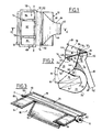
- the device shown in Figures 1 and 2 includes a housing 10, advantageously formed by molding a plastic material, comprising two lateral walls 12 and 14 parallel to one another (FIG. 1) which are connected to each other by different walls with parallel generatrices.
- the housing 10 comprises a connection endpiece 16, of generally rectangular section, which extends over the entire width of the housing between the walls 12 and 14.
- the endpiece 16 is suitable for being connected to the output of a power unit. fan (not shown) suitable for sending fresh air inside the housing.
- the nozzle 16 opens into a fresh air inlet pipe 18 which feeds, in a manner known per se, a branch 20 for transmitting fresh air and a branch 22 for reheating the air (FIG. 2).
- the branch 20 is limited upwards by a partition 24 with parallel generators which extends over the entire width of the housing and which is connected to the end piece 16.
- the branch 22 is limited downwards by a wall 26 with parallel generators which extends over the entire width of the housing and which is connected to the end piece 16.
- the branch 22 has a general U-shape, externally limited by the wall 26 and internally limited by a partition 28 extending over the entire width of the housing.
- the two ends of the U-shaped branch 22 respectively form an inlet section 30 and an outlet section 32 which communicate respectively upstream and downstream of the fresh air transmission branch 20.
- the branch 22 internally houses a heat exchanger 34 advantageously constituted by a radiator traversed by the coolant of the engine of the motor vehicle.
- the exchanger 34 makes it possible to heat the air which, penetrating by the inlet section 30 of the branch 22, comes out through its outlet section 32.
- the device further comprises a mixing flap 36 pivotally mounted around a transverse axis 38.
- the flap 36 is arranged at the junction of the inlet pipe 18, the fresh air transmission branch 20 and the air reheating branch 22 to distribute, at will, the flow of air circulating in the branches 20 and 22.
- the flap 36 can pivot between an extreme position (shown in solid lines) in which the air passes only through branch 22 to be heated and another extreme position (shown in broken lines) in which the air simply passes through branch 20, without being heated. All the intermediate positions are possible to adjust the distribution of the air between the branches 20 and 22 and consequently the temperature of this air.
- the branches 20 and 22 lead to a mixing zone which at the same time constitutes the air inlet 40 of a distribution chamber 42.
- the air inlet 40 extends over the entire width of the housing and is limited, in the perpendicular direction, by the wall 24 and by a wall portion 44 which extends the wall 26 at the outlet section 32 of the branch 22.
- the distribution chamber 42 extends over the entire width of the housing and is limited by a wall 46 of circular arc section, centered on an axis XX, parallel to the generatrices of the housing.
- the wall 46 is connected along a generator 48 with the wall 24 and is connected, at its other end, to an outlet mouth 49, of generally rectangular shape.
- the chamber 42 is limited by a wall 50 with parallel generators, extending over the entire width of the housing, and having a circular arc section centered on the axis XX.
- the wall 50 is connected with a wall 52, extending over the entire width of the housing and connecting with the mouth 49.
- This wall 52 is connected, on the side of the mouth 49, with a wall 54 which extends up to near the axis XX and which is connected with another internal wall 56 which itself connects to the wall 52 at its other end.
- the walls 46 and 54 define between them a first conduit 58 communicating the chamber 42 with the outlet mouth 49.
- the wall 50 is connected on the other hand with a wall 60 with parallel generators which ends up at an outlet 62 constituted by a mouth of generally rectangular shape and of narrower width than that of the housing.
- the wall 60 is connected laterally on two walls 64 and 66 which themselves are connected together by a wall 68 opposite the wall 50 ( Figure 2).
- the wall 68 joins the wall 26 and extends to the chamber 42.
- the wall 68 is connected, along an edge 70 to a recessed wall 72 itself connected to the wall 44.
- the walls 60, 64 , 66 and 68 delimit between them a second conduit 74 communicating the chamber 42 with the outlet 62.
- the first conduit 58 is divided by two transverse partitions 76 and 78 which extend perpendicular to the axis XX.
- the wall 76 connects the walls 46 and 54 (FIG. 2) by connecting in the upper part to the mouth 49 and is limited, in the lower part by an edge 80 substantially radial with respect to the axis XX. It is the same for the wall 78.
- the walls 76 and 78 thus delimit inside the conduit 58 three outlets: a central outlet 82 and two lateral outlets 84 each of rectangular shape (FIG. 1).
- the central outlet 82 is suitable for serving a ventilation opening at the level of the dashboard of the motor vehicle, the two lateral outlets 84 serving deicing / demisting openings of the windshield and the outlet 62 of the second conduit 74 serves a mouth in the lower part of the passenger compartment, corresponding to a so-called "feet" position.
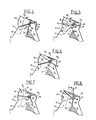
- the distribution of air between the aforementioned outlets is ensured by a single flap 86 which is mounted for rotation about the axis XX.
- the shutter 86 comprises (FIGS. 2 and 3) a first part 88 and a second part 90 disposed respectively on either side of the axis XX.
- the part 88 comprises a central blade 92 of generally rectangular shape suitable for controlling the outlet 82 and two lateral blades 94 suitable for controlling the two outputs 84.
- the second part 90 consists of a single blade 96 suitable for controlling the second conduit 74. As shown in FIG. 3, the blades 92 and 94 are offset axially and angularly with respect to the axis XX.
- the two lateral blades 94 are in the same plane while the central blade 92 is angularly offset relative to the plane of the two lateral blades, the single blade 96 of the second part 90 of the flap being in this case substantially in the same plane than that of the side blades but which can also be angularly offset if necessary.
- the two side blades 94 and the central blade 92 are generally rectangular plates each having one side attached to the pivot axis of the flap and three sides suitable for rubbing against the walls internal and / or internal partitions of the first duct.
- the blade 96 of the second part of the shutter also consists of a generally rectangular plate having one side attached to the pivot axis and three sides rubbing against the internal walls of the second duct.
- each of the blades which are not attached to the central axis, are provided with a seal 98, for example overmolded.
- the axis XX of the flap 86 is extended on one side by a pivot 100 and on the opposite side by a cylindrical bearing 102 comprising a drive means for said flap, such as a maneuvering square.
- the first part 88 of the shutter formed by the central blade 92 and the two lateral blades 94 as well as the second part 90, formed by the blade 96, extend over the same width, in the direction of the axis XX (figure 3).
- the central blade 92 of the flap 86 is supported on the wall 72 and closes the access to the second conduit 74.
- the two side blades 94 which are located at the edges 80 of the partitions 76 and 78 close the access to the lateral outlets 84.
- the blade 96 bears against the wall 56.
- the flap has pivoted slightly clockwise.
- the central blade 92 is slightly spaced from the wall 72 and the side blades 94 always close the side outlets 84.
- the blade 96 rubs against the internal face of the wall 50.
- the flap 86 has further pivoted.
- the central blade 92 is located at the lower edges 80 of the partitions 76 and 78 and thus closes the central opening 82.
- the lateral blades 94 close the lateral outlets 84 and the blade 96 always rubs against the internal face of the wall 50. Consequently, the fresh or heated air can only escape through the duct 74 and through the outlet 62. We are therefore in a so-called "feet" position.
Landscapes
- Physics & Mathematics (AREA)
- Thermal Sciences (AREA)
- Engineering & Computer Science (AREA)
- Mechanical Engineering (AREA)
- Air-Conditioning For Vehicles (AREA)
- Air-Flow Control Members (AREA)
- Exhaust Gas After Treatment (AREA)
Applications Claiming Priority (2)
| Application Number | Priority Date | Filing Date | Title |
|---|---|---|---|
| FR9003279 | 1990-03-14 | ||
| FR9003279A FR2659603B1 (fr) | 1990-03-14 | 1990-03-14 | Dispositif de chauffage et de ventilation de l'habitacle d'un vehicule automobile. |
Publications (2)
| Publication Number | Publication Date |
|---|---|
| EP0447304A1 EP0447304A1 (fr) | 1991-09-18 |
| EP0447304B1 true EP0447304B1 (fr) | 1993-08-18 |
Family
ID=9394735
Family Applications (1)
| Application Number | Title | Priority Date | Filing Date |
|---|---|---|---|
| EP91400647A Expired - Lifetime EP0447304B1 (fr) | 1990-03-14 | 1991-03-08 | Dispositif de chauffage et de ventilation de l'habitacle d'un véhicule automobile |
Country Status (8)
| Country | Link |
|---|---|
| US (1) | US5106018A (cs) |
| EP (1) | EP0447304B1 (cs) |
| JP (1) | JPH04221222A (cs) |
| CS (1) | CS65391A2 (cs) |
| DE (1) | DE69100274T2 (cs) |
| ES (1) | ES2046022T3 (cs) |
| FR (1) | FR2659603B1 (cs) |
| SK (1) | SK280761B6 (cs) |
Cited By (1)
| Publication number | Priority date | Publication date | Assignee | Title |
|---|---|---|---|---|
| DE10038994A1 (de) * | 2000-08-10 | 2002-02-21 | Behr Gmbh & Co | Strömungsregulierklappeneinheit und strömungsführende Struktur |
Families Citing this family (32)
| Publication number | Priority date | Publication date | Assignee | Title |
|---|---|---|---|---|
| ES2070070B1 (es) * | 1993-03-10 | 1998-10-16 | Frape Behr Sa | Sistema de distribucion para circuito de aireacion y distribuidor correspondiente. |
| FR2703304B1 (fr) * | 1993-03-31 | 1995-06-23 | Valeo Thermique Habitacle | Boitier de distribution pour une installation de chauffage-ventilation de l'habitacle d'un vehicule automobile. |
| FR2715352B1 (fr) * | 1994-01-24 | 1996-04-19 | Valeo Thermique Habitacle | Dispositif de chauffage-ventilation de l'habitacle d'un véhicule automobile. |
| FR2717127B1 (fr) * | 1994-03-11 | 1996-07-05 | Valeo Thermique Habitacle | Dispositif de chauffage pour véhicule avec dégivrage des vitres latérales. |
| US6474406B2 (en) | 1995-10-02 | 2002-11-05 | Calsonic Kansei Corporation | Heater/cooler unit of automotive air conditioning system |
| KR100316163B1 (ko) * | 1996-07-27 | 2002-12-05 | 한라공조주식회사 | 공기조화장치 |
| JPH10100655A (ja) * | 1996-09-26 | 1998-04-21 | Denso Corp | 自動車用空調装置のクーリングユニット |
| DE19650909C1 (de) * | 1996-12-07 | 1997-12-04 | Daimler Benz Ag | Heizungs- oder Klimaanlage |
| JP3758262B2 (ja) * | 1996-12-25 | 2006-03-22 | 株式会社デンソー | 空気調和装置 |
| DE19734145C1 (de) * | 1997-08-07 | 1998-07-23 | Daimler Benz Ag | Klimaanlage für Fahrzeuge |
| FR2771343B1 (fr) * | 1997-11-27 | 2000-01-28 | Valeo Climatisation | Dispositif de distribution d'air pour un appareil de chauffage et/ou climatisation de vehicule automobile |
| FR2796335B1 (fr) * | 1999-07-12 | 2001-10-05 | Valeo Climatisation | Installation de chauffage et notamment de chauffage- climatisation du type presentant un volet de mixage |
| JP4253960B2 (ja) * | 1999-11-18 | 2009-04-15 | 株式会社デンソー | 車両用空調装置 |
| JP2003159927A (ja) * | 2001-11-22 | 2003-06-03 | Denso Corp | 車両用空調装置 |
| US6772833B2 (en) * | 2002-07-23 | 2004-08-10 | Visteon Global Technologies, Inc. | HVAC system with modular inserts |
| DE10320645A1 (de) * | 2003-05-07 | 2004-12-02 | Behr Gmbh & Co. Kg | Klappe für Luftkanäle und Strömungsleiteinrichtung |
| KR100596254B1 (ko) * | 2004-06-17 | 2006-07-03 | 엘지전자 주식회사 | 분리형 공기조화기의 실내기 |
| KR101146430B1 (ko) * | 2005-03-29 | 2012-05-18 | 한라공조주식회사 | 차량용 후석 공조장치 |
| US7228689B2 (en) * | 2005-05-20 | 2007-06-12 | Delphi Technologies, Inc. | Thermo-electric and HVAC seat cooling and heating mode door integration |
| DE102005047253B3 (de) * | 2005-10-01 | 2007-02-15 | Visteon Global Technologies, Inc., Van Buren Township | Vorrichtung zur Steuerung der Luftströmungsmengen in die Armaturenbrettluftauslässe einer Kraftfahrzeug-Heizungs- oder Klimaanlage |
| US8544533B2 (en) * | 2005-11-10 | 2013-10-01 | Halla Climate Control Corporation | Vehicular air conditioner having two-layered air flow |
| US20070243812A1 (en) * | 2006-03-27 | 2007-10-18 | Behr America, Inc. | Device for ventilating a vehicle |
| US8382563B2 (en) * | 2007-11-08 | 2013-02-26 | Visteon Global Technologies, Inc. | Multi-zone control module for a heating, ventilation, and air conditioning system |
| US7954540B2 (en) * | 2008-12-18 | 2011-06-07 | Delphi Technologies, Inc. | HVAC assembly including temperature mixing valve |
| JP6054191B2 (ja) * | 2013-01-31 | 2016-12-27 | カルソニックカンセイ株式会社 | 空調ユニット用ドア構造および空調ユニット |
| DE102013104461B4 (de) * | 2013-05-02 | 2022-06-09 | Denso Automotive Deutschland Gmbh | Klimatisierungseinrichtung für ein Kraftfahrzeug |
| US10220668B2 (en) * | 2013-10-08 | 2019-03-05 | Denso International America, Inc. | HVAC temperature control bypass throttle |
| DE102014105115B8 (de) * | 2014-04-10 | 2025-04-30 | Hanon Systems | Luftleiteinrichtung einer Klimatisierungsvorrichtung eines Kraftfahrzeugs |
| DE102014217163B4 (de) | 2014-08-28 | 2025-03-06 | Mahle International Gmbh | Luftsteuereinrichtung mit Lagerstelle |
| JP6157657B2 (ja) * | 2015-02-06 | 2017-07-05 | ハンオン システムズ | 車両用ファンシュラウド |
| DE102019205929A1 (de) * | 2019-04-25 | 2020-10-29 | Mahle International Gmbh | Kraftfahrzeugklimaanlage |
| JP7372093B2 (ja) * | 2019-09-18 | 2023-10-31 | 三菱重工サーマルシステムズ株式会社 | 車両用空気吹き出し装置 |
Family Cites Families (15)
| Publication number | Priority date | Publication date | Assignee | Title |
|---|---|---|---|---|
| GB1227334A (cs) * | 1967-07-11 | 1971-04-07 | ||
| DE2648663A1 (de) * | 1976-10-27 | 1978-05-03 | Volkswagenwerk Ag | Belueftungsvorrichtung fuer den innenraum eines fahrzeugs |
| DE2836800A1 (de) * | 1978-08-23 | 1980-03-06 | Volkswagenwerk Ag | Heiz- und belueftungsvorrichtung fuer ein fahrzeug |
| FR2437312A1 (fr) * | 1978-09-29 | 1980-04-25 | Renault | Dispositif de climatisation d'un habitacle de vehicule automobile |
| JPS5726008A (en) * | 1980-07-18 | 1982-02-12 | Nippon Denso Co Ltd | Air conditioning device for automobile |
| SE436112B (sv) * | 1981-04-01 | 1984-11-12 | Saab Scania Ab | Klimatsystem for fordon |
| JPS6228492Y2 (cs) * | 1981-04-17 | 1987-07-22 | ||
| JPS60209318A (ja) * | 1984-04-04 | 1985-10-21 | Nissan Motor Co Ltd | 自動車用空気調和装置のヒ−タユニツト |
| DE3421323A1 (de) * | 1984-06-08 | 1985-12-12 | Audi AG, 8070 Ingolstadt | Luftverteileinrichtung fuer kraftfahrzeuge |
| DE3529940C3 (de) * | 1985-08-21 | 1999-11-04 | Valeo Klimasysteme Gmbh | Heiz- und Klimagerät für Kraftfahrzeuge |
| IT210804Z2 (it) * | 1987-06-26 | 1989-01-11 | Borletti Climatizzazione | Distributore a tamburo per impianti di climatizzazione di autoveicoli |
| DE3805168A1 (de) * | 1988-02-19 | 1989-08-31 | Ford Werke Ag | Verteileinrichtung fuer heiz- und belueftungsanlagen von kraftfahrzeugen |
| FR2631896B1 (fr) * | 1988-05-27 | 1990-08-24 | Valeo | Boitier de distribution pour dispositif de chauffage et/ou de climatisation, notamment pour vehicule automobile |
| US4842047A (en) * | 1988-06-03 | 1989-06-27 | Diesel Kiki Co., Ltd. | Air conditioner for automobiles |
| DE3823448A1 (de) * | 1988-07-11 | 1990-01-18 | Bosch Gmbh Robert | Vorrichtung zum beheizen des fahrgastraumes eines kraftfahrzeuges |
-
1990
- 1990-03-14 FR FR9003279A patent/FR2659603B1/fr not_active Expired - Lifetime
-
1991
- 1991-03-08 EP EP91400647A patent/EP0447304B1/fr not_active Expired - Lifetime
- 1991-03-08 DE DE91400647T patent/DE69100274T2/de not_active Expired - Lifetime
- 1991-03-08 ES ES91400647T patent/ES2046022T3/es not_active Expired - Lifetime
- 1991-03-13 CS CS91653A patent/CS65391A2/cs unknown
- 1991-03-13 SK SK653-91A patent/SK280761B6/sk unknown
- 1991-03-13 US US07/669,016 patent/US5106018A/en not_active Expired - Fee Related
- 1991-03-14 JP JP3073758A patent/JPH04221222A/ja active Pending
Cited By (1)
| Publication number | Priority date | Publication date | Assignee | Title |
|---|---|---|---|---|
| DE10038994A1 (de) * | 2000-08-10 | 2002-02-21 | Behr Gmbh & Co | Strömungsregulierklappeneinheit und strömungsführende Struktur |
Also Published As
| Publication number | Publication date |
|---|---|
| ES2046022T3 (es) | 1994-01-16 |
| CS65391A2 (en) | 1991-11-12 |
| EP0447304A1 (fr) | 1991-09-18 |
| SK280761B6 (sk) | 2000-07-11 |
| JPH04221222A (ja) | 1992-08-11 |
| FR2659603B1 (fr) | 1992-06-05 |
| DE69100274T2 (de) | 1993-12-09 |
| FR2659603A1 (fr) | 1991-09-20 |
| DE69100274D1 (de) | 1993-09-23 |
| US5106018A (en) | 1992-04-21 |
Similar Documents
| Publication | Publication Date | Title |
|---|---|---|
| EP0447304B1 (fr) | Dispositif de chauffage et de ventilation de l'habitacle d'un véhicule automobile | |
| FR2703304A1 (fr) | Boîtier de distribution pour une installation de chauffage-ventilation de l'habitacle d'un véhicule automobile. | |
| EP1013491B1 (fr) | Dispositif de chauffage et/ou climatisation de véhicule automobile à mixage d'air amélioré | |
| FR2650224A1 (fr) | Dispositif de chauffage et de ventilation pour l'habitacle d'un vehicule automobile | |
| EP0777584A1 (fr) | Dispositif de chauffage-ventilation et/ou de climatisation de l'habitacle d'un vehicule automobile | |
| FR2659907A1 (fr) | Dispositif de chauffage et de ventilation avec moyens separes de reglage de temperature aux places avant de l'habitacle d'un vehicule automobile. | |
| EP0578582A1 (fr) | Dispositif de chauffage-ventilation et/ou de climatisation de l'habitacle d'un véhicule automobile | |
| EP4021744A1 (fr) | Dispostif de chauffage, ventilation et/ou climatisation pour véhicule automobile | |
| FR2715352A1 (fr) | Dispositif de chauffage-ventilation de l'habitacle d'un véhicule automobile. | |
| EP0709241B1 (fr) | Dispositif de chauffage et/ou d'aération pour l'habitacle d'un véhicule automobile | |
| EP0812714B1 (fr) | Dispositif de chauffage-ventilation pour l'habitacle d'un véhicule automobile | |
| FR2720693A1 (fr) | Dispositif de chauffage et/ou d'aération de l'habitacle d'un véhicule. | |
| FR2778148A1 (fr) | Dispositif de chauffage-ventilation de l'habitacle d'un vehicule automobile | |
| FR2788019A1 (fr) | Dispositif de distribution d'air pour le chauffage et/ou la climatisation d'un vehicule automobile | |
| FR2794069A1 (fr) | Distributeur d'air d'un dispositif de chauffage-ventilation et/ou climatisation d'un vehicule automobile | |
| FR2614244A1 (fr) | Dispositif de chauffage et de ventilation, notamment pour l'habitacle d'un vehicule automobile. | |
| WO2020174146A1 (fr) | Installation de chauffage et/ou ventilation et/ou climatisation comportant un volet de mixage avec déflecteur | |
| FR2719809A1 (fr) | Dispositif de chauffage-ventilation de l'habitacle d'un véhicule. | |
| FR2479106A1 (fr) | Dispositif de chauffage et d'aeration pour vehicule automobile | |
| EP0742114B1 (fr) | Dispositif de chauffage-ventilation de l'habitacle d'un véhicule automobile | |
| FR2710878A1 (fr) | Dispositif du chauffage et de ventilation de l'habitacle d'un véhicule automobile. | |
| FR2786134A1 (fr) | Dispositif de chauffage-ventilation de l'habitacle d'un vehicule | |
| FR2773111A1 (fr) | Dispositif de chauffage et/ou climatisation a mixage d'air pour vehicule automobile | |
| FR2616212A1 (fr) | Dispositif d'aeration et de chauffage par air chaud a radiateur pivotant | |
| EP0749857B1 (fr) | Dispositif de chauffage-ventilation de l'habitacle d'un véhicule automobile |
Legal Events
| Date | Code | Title | Description |
|---|---|---|---|
| PUAI | Public reference made under article 153(3) epc to a published international application that has entered the european phase |
Free format text: ORIGINAL CODE: 0009012 |
|
| AK | Designated contracting states |
Kind code of ref document: A1 Designated state(s): DE ES GB IT SE |
|
| 17P | Request for examination filed |
Effective date: 19920110 |
|
| 17Q | First examination report despatched |
Effective date: 19930205 |
|
| GRAA | (expected) grant |
Free format text: ORIGINAL CODE: 0009210 |
|
| AK | Designated contracting states |
Kind code of ref document: B1 Designated state(s): DE ES GB IT SE |
|
| GBT | Gb: translation of ep patent filed (gb section 77(6)(a)/1977) |
Effective date: 19930819 |
|
| REF | Corresponds to: |
Ref document number: 69100274 Country of ref document: DE Date of ref document: 19930923 |
|
| ITF | It: translation for a ep patent filed | ||
| REG | Reference to a national code |
Ref country code: ES Ref legal event code: FG2A Ref document number: 2046022 Country of ref document: ES Kind code of ref document: T3 |
|
| PGFP | Annual fee paid to national office [announced via postgrant information from national office to epo] |
Ref country code: ES Payment date: 19940325 Year of fee payment: 4 |
|
| ITTA | It: last paid annual fee | ||
| PLBE | No opposition filed within time limit |
Free format text: ORIGINAL CODE: 0009261 |
|
| STAA | Information on the status of an ep patent application or granted ep patent |
Free format text: STATUS: NO OPPOSITION FILED WITHIN TIME LIMIT |
|
| 26N | No opposition filed | ||
| EAL | Se: european patent in force in sweden |
Ref document number: 91400647.3 |
|
| PG25 | Lapsed in a contracting state [announced via postgrant information from national office to epo] |
Ref country code: ES Free format text: LAPSE BECAUSE OF NON-PAYMENT OF DUE FEES Effective date: 19950309 |
|
| REG | Reference to a national code |
Ref country code: ES Ref legal event code: FD2A Effective date: 19990503 |
|
| PGFP | Annual fee paid to national office [announced via postgrant information from national office to epo] |
Ref country code: SE Payment date: 20000221 Year of fee payment: 10 |
|
| PGFP | Annual fee paid to national office [announced via postgrant information from national office to epo] |
Ref country code: GB Payment date: 20000229 Year of fee payment: 10 |
|
| PG25 | Lapsed in a contracting state [announced via postgrant information from national office to epo] |
Ref country code: GB Free format text: LAPSE BECAUSE OF NON-PAYMENT OF DUE FEES Effective date: 20010308 |
|
| PG25 | Lapsed in a contracting state [announced via postgrant information from national office to epo] |
Ref country code: SE Free format text: LAPSE BECAUSE OF NON-PAYMENT OF DUE FEES Effective date: 20010309 |
|
| GBPC | Gb: european patent ceased through non-payment of renewal fee |
Effective date: 20010308 |
|
| EUG | Se: european patent has lapsed |
Ref document number: 91400647.3 |
|
| PG25 | Lapsed in a contracting state [announced via postgrant information from national office to epo] |
Ref country code: IT Free format text: LAPSE BECAUSE OF NON-PAYMENT OF DUE FEES;WARNING: LAPSES OF ITALIAN PATENTS WITH EFFECTIVE DATE BEFORE 2007 MAY HAVE OCCURRED AT ANY TIME BEFORE 2007. THE CORRECT EFFECTIVE DATE MAY BE DIFFERENT FROM THE ONE RECORDED. Effective date: 20050308 |
|
| PGFP | Annual fee paid to national office [announced via postgrant information from national office to epo] |
Ref country code: DE Payment date: 20100315 Year of fee payment: 20 |
|
| REG | Reference to a national code |
Ref country code: DE Ref legal event code: R071 Ref document number: 69100274 Country of ref document: DE |
|
| PG25 | Lapsed in a contracting state [announced via postgrant information from national office to epo] |
Ref country code: DE Free format text: LAPSE BECAUSE OF EXPIRATION OF PROTECTION Effective date: 20110308 |