EP0447304B1 - Device for heating and ventilation of a motor vehicle compartment - Google Patents
Device for heating and ventilation of a motor vehicle compartment Download PDFInfo
- Publication number
- EP0447304B1 EP0447304B1 EP91400647A EP91400647A EP0447304B1 EP 0447304 B1 EP0447304 B1 EP 0447304B1 EP 91400647 A EP91400647 A EP 91400647A EP 91400647 A EP91400647 A EP 91400647A EP 0447304 B1 EP0447304 B1 EP 0447304B1
- Authority
- EP
- European Patent Office
- Prior art keywords
- duct
- air
- valve
- distribution
- outlet
- Prior art date
- Legal status (The legal status is an assumption and is not a legal conclusion. Google has not performed a legal analysis and makes no representation as to the accuracy of the status listed.)
- Expired - Lifetime
Links
Images
Classifications
-
- B—PERFORMING OPERATIONS; TRANSPORTING
- B60—VEHICLES IN GENERAL
- B60H—ARRANGEMENTS OF HEATING, COOLING, VENTILATING OR OTHER AIR-TREATING DEVICES SPECIALLY ADAPTED FOR PASSENGER OR GOODS SPACES OF VEHICLES
- B60H1/00—Heating, cooling or ventilating [HVAC] devices
- B60H1/00642—Control systems or circuits; Control members or indication devices for heating, cooling or ventilating devices
- B60H1/00664—Construction or arrangement of damper doors
- B60H1/00671—Damper doors moved by rotation; Grilles
- B60H1/00678—Damper doors moved by rotation; Grilles the axis of rotation being in the door plane, e.g. butterfly doors
-
- B—PERFORMING OPERATIONS; TRANSPORTING
- B60—VEHICLES IN GENERAL
- B60H—ARRANGEMENTS OF HEATING, COOLING, VENTILATING OR OTHER AIR-TREATING DEVICES SPECIALLY ADAPTED FOR PASSENGER OR GOODS SPACES OF VEHICLES
- B60H1/00—Heating, cooling or ventilating [HVAC] devices
- B60H1/00642—Control systems or circuits; Control members or indication devices for heating, cooling or ventilating devices
- B60H1/00664—Construction or arrangement of damper doors
- B60H2001/00714—Details of seals of damper doors
Definitions
- the invention relates to a device for heating and ventilating the passenger compartment of a motor vehicle, of the type comprising a housing delimiting a distribution chamber and providing an air inlet for introducing fresh or heated air into the chamber distribution and air outlets to distribute this fresh or heated air in different areas of the passenger compartment, a distribution flap being pivotally mounted around an axis inside the distribution chamber to adjust at will the distribution of the air distributed by the air outlets.
- an air outlet forming an air vent at the dashboard, an air outlet forming a defrosting / defogging mouth of the windshield and an air outlet forming a mouth in the lower part of the passenger compartment.
- a device of this type is known from French Patent FR-A-2,503,056, in the name of SAAB-SCANIA AKTIEBOLAG.
- This known device has the advantage of using a single distribution flap, instead of usually two flaps, to ensure the distribution of air through the outlets.
- this known device only offers a limited number of modes of distributing fresh or heated air through the air outlets of the device.
- the device housing delimits a first conduit which comprises at least one internal partition extending partially inside the distribution chamber and perpendicular to the pivot axis of the distribution flap to form at least two adjacent air outlets, the housing further defines a second duct which forms another air outlet, and the distribution flap comprises a first part and a second part extending respectively on either side of the pivot axis, the first part of the flap comprising at least two blades offset axially and angularly between them to selectively control the distribution of air through the outlets of the first duct, and the second part of the flap comprising a blade to control the distribution of air through the outlet of the second duct.
- the shutter of the invention comprises vanes offset angularly and axially controlling different outlets, it is thus possible to ensure five different distribution modes depending on the angular position of the shutter.
- the first duct has two internal partitions forming three adjacent air outlets, namely a central outlet and two lateral outlets
- the first part of the distribution flap comprises three blades offset axially and angularly between them, namely a central dawn and two side blades suitable for controlling the central outlet and the two aforementioned side outputs respectively
- the second part of the flap comprises a single blade suitable for controlling the outlet of the second conduit.
- the two lateral blades are in the same plane, while the central blade is angularly offset relative to the plane of the two lateral blades, the single blade of the second part of the shutter being substantially in the same plane as that of the blades side.
- the central outlet serves a ventilation opening at the level of the dashboard, the lateral exits respectively serve deicing / defogging vents of the windshield, while the outlet of the second duct serves a mouth in the lower part of the cabin.
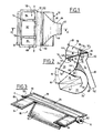
- the device shown in Figures 1 and 2 includes a housing 10, advantageously formed by molding a plastic material, comprising two lateral walls 12 and 14 parallel to one another (FIG. 1) which are connected to each other by different walls with parallel generatrices.
- the housing 10 comprises a connection endpiece 16, of generally rectangular section, which extends over the entire width of the housing between the walls 12 and 14.
- the endpiece 16 is suitable for being connected to the output of a power unit. fan (not shown) suitable for sending fresh air inside the housing.
- the nozzle 16 opens into a fresh air inlet pipe 18 which feeds, in a manner known per se, a branch 20 for transmitting fresh air and a branch 22 for reheating the air (FIG. 2).
- the branch 20 is limited upwards by a partition 24 with parallel generators which extends over the entire width of the housing and which is connected to the end piece 16.
- the branch 22 is limited downwards by a wall 26 with parallel generators which extends over the entire width of the housing and which is connected to the end piece 16.
- the branch 22 has a general U-shape, externally limited by the wall 26 and internally limited by a partition 28 extending over the entire width of the housing.
- the two ends of the U-shaped branch 22 respectively form an inlet section 30 and an outlet section 32 which communicate respectively upstream and downstream of the fresh air transmission branch 20.
- the branch 22 internally houses a heat exchanger 34 advantageously constituted by a radiator traversed by the coolant of the engine of the motor vehicle.
- the exchanger 34 makes it possible to heat the air which, penetrating by the inlet section 30 of the branch 22, comes out through its outlet section 32.
- the device further comprises a mixing flap 36 pivotally mounted around a transverse axis 38.
- the flap 36 is arranged at the junction of the inlet pipe 18, the fresh air transmission branch 20 and the air reheating branch 22 to distribute, at will, the flow of air circulating in the branches 20 and 22.
- the flap 36 can pivot between an extreme position (shown in solid lines) in which the air passes only through branch 22 to be heated and another extreme position (shown in broken lines) in which the air simply passes through branch 20, without being heated. All the intermediate positions are possible to adjust the distribution of the air between the branches 20 and 22 and consequently the temperature of this air.
- the branches 20 and 22 lead to a mixing zone which at the same time constitutes the air inlet 40 of a distribution chamber 42.
- the air inlet 40 extends over the entire width of the housing and is limited, in the perpendicular direction, by the wall 24 and by a wall portion 44 which extends the wall 26 at the outlet section 32 of the branch 22.
- the distribution chamber 42 extends over the entire width of the housing and is limited by a wall 46 of circular arc section, centered on an axis XX, parallel to the generatrices of the housing.
- the wall 46 is connected along a generator 48 with the wall 24 and is connected, at its other end, to an outlet mouth 49, of generally rectangular shape.
- the chamber 42 is limited by a wall 50 with parallel generators, extending over the entire width of the housing, and having a circular arc section centered on the axis XX.
- the wall 50 is connected with a wall 52, extending over the entire width of the housing and connecting with the mouth 49.
- This wall 52 is connected, on the side of the mouth 49, with a wall 54 which extends up to near the axis XX and which is connected with another internal wall 56 which itself connects to the wall 52 at its other end.
- the walls 46 and 54 define between them a first conduit 58 communicating the chamber 42 with the outlet mouth 49.
- the wall 50 is connected on the other hand with a wall 60 with parallel generators which ends up at an outlet 62 constituted by a mouth of generally rectangular shape and of narrower width than that of the housing.
- the wall 60 is connected laterally on two walls 64 and 66 which themselves are connected together by a wall 68 opposite the wall 50 ( Figure 2).
- the wall 68 joins the wall 26 and extends to the chamber 42.
- the wall 68 is connected, along an edge 70 to a recessed wall 72 itself connected to the wall 44.
- the walls 60, 64 , 66 and 68 delimit between them a second conduit 74 communicating the chamber 42 with the outlet 62.
- the first conduit 58 is divided by two transverse partitions 76 and 78 which extend perpendicular to the axis XX.
- the wall 76 connects the walls 46 and 54 (FIG. 2) by connecting in the upper part to the mouth 49 and is limited, in the lower part by an edge 80 substantially radial with respect to the axis XX. It is the same for the wall 78.
- the walls 76 and 78 thus delimit inside the conduit 58 three outlets: a central outlet 82 and two lateral outlets 84 each of rectangular shape (FIG. 1).
- the central outlet 82 is suitable for serving a ventilation opening at the level of the dashboard of the motor vehicle, the two lateral outlets 84 serving deicing / demisting openings of the windshield and the outlet 62 of the second conduit 74 serves a mouth in the lower part of the passenger compartment, corresponding to a so-called "feet" position.
- the distribution of air between the aforementioned outlets is ensured by a single flap 86 which is mounted for rotation about the axis XX.
- the shutter 86 comprises (FIGS. 2 and 3) a first part 88 and a second part 90 disposed respectively on either side of the axis XX.
- the part 88 comprises a central blade 92 of generally rectangular shape suitable for controlling the outlet 82 and two lateral blades 94 suitable for controlling the two outputs 84.
- the second part 90 consists of a single blade 96 suitable for controlling the second conduit 74. As shown in FIG. 3, the blades 92 and 94 are offset axially and angularly with respect to the axis XX.
- the two lateral blades 94 are in the same plane while the central blade 92 is angularly offset relative to the plane of the two lateral blades, the single blade 96 of the second part 90 of the flap being in this case substantially in the same plane than that of the side blades but which can also be angularly offset if necessary.
- the two side blades 94 and the central blade 92 are generally rectangular plates each having one side attached to the pivot axis of the flap and three sides suitable for rubbing against the walls internal and / or internal partitions of the first duct.
- the blade 96 of the second part of the shutter also consists of a generally rectangular plate having one side attached to the pivot axis and three sides rubbing against the internal walls of the second duct.
- each of the blades which are not attached to the central axis, are provided with a seal 98, for example overmolded.
- the axis XX of the flap 86 is extended on one side by a pivot 100 and on the opposite side by a cylindrical bearing 102 comprising a drive means for said flap, such as a maneuvering square.
- the first part 88 of the shutter formed by the central blade 92 and the two lateral blades 94 as well as the second part 90, formed by the blade 96, extend over the same width, in the direction of the axis XX (figure 3).
- the central blade 92 of the flap 86 is supported on the wall 72 and closes the access to the second conduit 74.
- the two side blades 94 which are located at the edges 80 of the partitions 76 and 78 close the access to the lateral outlets 84.
- the blade 96 bears against the wall 56.
- the flap has pivoted slightly clockwise.
- the central blade 92 is slightly spaced from the wall 72 and the side blades 94 always close the side outlets 84.
- the blade 96 rubs against the internal face of the wall 50.
- the flap 86 has further pivoted.
- the central blade 92 is located at the lower edges 80 of the partitions 76 and 78 and thus closes the central opening 82.
- the lateral blades 94 close the lateral outlets 84 and the blade 96 always rubs against the internal face of the wall 50. Consequently, the fresh or heated air can only escape through the duct 74 and through the outlet 62. We are therefore in a so-called "feet" position.
Description
L'invention concerne un dispositif de chauffage et de ventilation de l'habitacle d'un véhicule automobile, du type comprenant un boîtier délimitant une chambre de distribution et ménageant une entrée d'air pour introduire de l'air frais ou réchauffé dans la chambre de distribution et des sorties d'air pour distribuer cet air frais ou réchauffé en différentes zones de l'habitacle, un volet de distribution étant monté à pivotement autour d'un axe à l'intérieur de la chambre de distribution pour régler à volonté la répartition de l'air distribué par les sorties d'air.The invention relates to a device for heating and ventilating the passenger compartment of a motor vehicle, of the type comprising a housing delimiting a distribution chamber and providing an air inlet for introducing fresh or heated air into the chamber distribution and air outlets to distribute this fresh or heated air in different areas of the passenger compartment, a distribution flap being pivotally mounted around an axis inside the distribution chamber to adjust at will the distribution of the air distributed by the air outlets.
Dans les dispositifs connus de ce type, on prévoit habituellement une sortie d'air formant bouche d'aération au niveau de la planche de bord, une sortie d'air formant bouche de dégivrage/désembuage du pare-brise et une sortie d'air formant bouche en partie basse de l'habitacle.In known devices of this type, there is usually provided an air outlet forming an air vent at the dashboard, an air outlet forming a defrosting / defogging mouth of the windshield and an air outlet forming a mouth in the lower part of the passenger compartment.
Un dispositif de ce type est connu d'après le Brevet français FR-A-2 503 056, au nom de SAAB-SCANIA AKTIEBOLAG. Ce dispositif connu a pour avantage de faire appel à un seul volet de distribution, au lieu de deux volets habituellement, pour assurer la distribution de l'air à travers les sorties.A device of this type is known from French Patent FR-A-2,503,056, in the name of SAAB-SCANIA AKTIEBOLAG. This known device has the advantage of using a single distribution flap, instead of usually two flaps, to ensure the distribution of air through the outlets.
Toutefois, du fait qu'il comporte un seul volet de distribution, ce dispositif connu n'offre qu'un nombre limité de modes de distribution de l'air frais ou réchauffé à travers les sorties d'air du dispositif.However, due to the fact that it comprises a single distribution flap, this known device only offers a limited number of modes of distributing fresh or heated air through the air outlets of the device.
Or, les cahiers des charges des constructeurs automobiles imposent actuellement aux dispositifs de ce type de pouvoir assurer au moins cinq modes de distribution différents, pas possible avec le dispositif du Brevet français précité.However, the specifications of car manufacturers currently require devices of this type to be able to provide at least five different distribution modes, not possible with the device of the aforementioned French patent.
C'est, en conséquence, un but de l'invention de procurer un dispositif du type défini en introduction qui permet, tout en utilisant un seul volet de distribution, d'offrir au moins cinq modes de distribution différents.It is therefore an object of the invention to provide a device of the type defined in the introduction which makes it possible, while using a single distribution flap, to offer at least five different distribution modes.
Conformément à l'invention, le boîtier du dispositif délimite un premier conduit qui comporte au moins une cloison interne s'étendant partiellement à l'intérieur de la chambre de distribution et perpendiculairement à l'axe de pivotement du volet de distribution pour former au moins deux sorties d'air adjacentes, le boîtier délimite en outre un second conduit qui forme une autre sortie d'air, et le volet de distribution comprend une première partie et une seconde partie s'étendant respectivement de part et d'autre de l'axe de pivotement, la première partie de volet comportant au moins deux aubes décalées axialement et angulairement entre elles pour contrôler sélectivement la distribution de l'air par les sorties du premier conduit, et la seconde partie de volet comportant une aube pour contrôler la distribution de l'air par la sortie du second conduit.According to the invention, the device housing delimits a first conduit which comprises at least one internal partition extending partially inside the distribution chamber and perpendicular to the pivot axis of the distribution flap to form at least two adjacent air outlets, the housing further defines a second duct which forms another air outlet, and the distribution flap comprises a first part and a second part extending respectively on either side of the pivot axis, the first part of the flap comprising at least two blades offset axially and angularly between them to selectively control the distribution of air through the outlets of the first duct, and the second part of the flap comprising a blade to control the distribution of air through the outlet of the second duct.
Comme le volet de l'invention comprend des aubes décalées angulairement et axialement contrôlant des sorties différentes, il est possible d'assurer ainsi cinq modes de distribution différents en fonction de la position angulaire du volet.As the shutter of the invention comprises vanes offset angularly and axially controlling different outlets, it is thus possible to ensure five different distribution modes depending on the angular position of the shutter.
Dans une forme de réalisation préférée de l'invention, le premier conduit comporte deux cloisons internes formant trois sorties d'air adjacentes, à savoir une sortie centrale et deux sorties latérales, la première partie du volet de distribution comprend trois aubes décalées axialement et angulairement entre elles, à savoir une aube centrale et deux aubes latérales propres à contrôler respectivement la sortie centrale et les deux sorties latérales précitées, tandis que la seconde partie du volet comprend une aube unique propre à contrôler la sortie du second conduit.In a preferred embodiment of the invention, the first duct has two internal partitions forming three adjacent air outlets, namely a central outlet and two lateral outlets, the first part of the distribution flap comprises three blades offset axially and angularly between them, namely a central dawn and two side blades suitable for controlling the central outlet and the two aforementioned side outputs respectively, while the second part of the flap comprises a single blade suitable for controlling the outlet of the second conduit.
Avantageusement, les deux aubes latérales sont dans le même plan, tandis que l'aube centrale est décalée angulairement par rapport au plan des deux aubes latérales, l'aube unique de la seconde partie du volet étant sensiblement dans le même plan que celui des aubes latérales.Advantageously, the two lateral blades are in the same plane, while the central blade is angularly offset relative to the plane of the two lateral blades, the single blade of the second part of the shutter being substantially in the same plane as that of the blades side.
Avantageusement, la sortie centrale dessert une bouche d'aération au niveau de la planche de bord, les sorties latérales desservent respectivement des bouches de dégivrage/désembuage du pare-brise, tandis que la sortie du second conduit dessert une bouche en partie basse de l'habitacle.Advantageously, the central outlet serves a ventilation opening at the level of the dashboard, the lateral exits respectively serve deicing / defogging vents of the windshield, while the outlet of the second duct serves a mouth in the lower part of the cabin.
Dans la description qui suit, donnée seulement à titre d'exemple, on se réfère aux dessins annexés, sur lesquels :
- la figure 1 est une vue de dessus d'un dispositif de chauffage et de ventilation selon l'invention ;
- la figure 2 est une vue en coupe suivant la ligne II-II de la figure 1 ;
- la figure 3 est une vue en perspective du volet de distribution du dispositif des figures 1 et 2 ; et
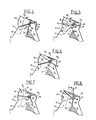
- les figures 4 à 8 sont des vues partielles en coupe, analogues à celle de la figure 2, montrant cinq positions différentes du volet de distribution assurant cinq modes de distribution différents.
- Figure 1 is a top view of a heating and ventilation device according to the invention;
- Figure 2 is a sectional view along line II-II of Figure 1;
- Figure 3 is a perspective view of the dispensing flap of the device of Figures 1 and 2; and
- Figures 4 to 8 are partial sectional views, similar to that of Figure 2, showing five different positions of the distribution flap ensuring five different distribution modes.
Le dispositif représenté aux figures 1 et 2 comprend un boîtier 10, avantageusement formé par moulage d'une matière plastique, comportant deux parois latérales 12 et 14 parallèles entre elles (figure 1) qui sont reliées entre elles par différentes parois à génératrices parallèles.The device shown in Figures 1 and 2 includes a
Le boîtier 10 comprend un embout de raccordement 16, de section générale rectangulaire, qui s'étend sur toute la largeur du boîtier entre les parois 12 et 14. L'embout 16 est propre à être raccordé à la sortie d'un groupe moto-ventilateur (non représenté) propre à envoyer de l'air frais à l'intérieur du boîtier.The
L'embout 16 débouche dans une conduite d'entrée d'air frais 18 qui alimente, de manière en soi connue, une branche 20 de transmission d'air frais et une branche 22 de réchauffage d'air (figure 2).The
La branche 20 est limitée vers le haut par une cloison 24 à génératrices parallèles qui s'étend sur toute la largeur du boîtier et qui se raccorde sur l'embout 16. La branche 22 est limitée vers le bas par une paroi 26 à génératrices parallèles qui s'étend sur toute la largeur du boîtier et qui se raccorde sur l'embout 16. La branche 22 a une forme générale de U, limitée extérieurement par la paroi 26 et limitée intérieurement par une cloison 28 s'étendant sur toute la largeur du boîtier. Les deux extrémités de la branche 22 en forme de U forment respectivement une section d'entrée 30 et une section de sortie 32 qui communiquent respectivement en amont et en aval de la branche de transmission d'air frais 20.The
La branche 22 loge intérieurement un échangeur de chaleur 34 avantageusement constitué par un radiateur parcouru par le fluide de refroidissement du moteur du véhicule automobile. L'échangeur 34 permet de réchauffer l'air qui, pénétrant par la section d'entrée 30 de la branche 22, ressort par sa section de sortie 32.The
Le dispositif comprend en outre un volet de mixage 36 monté à pivotement autour d'un axe transversal 38. Le volet 36 est disposé à la jonction de la conduite d'entrée 18, de la branche de transmission d'air frais 20 et de la branche de réchauffage d'air 22 pour répartir, à volonté, le débit de l'air circulant dans les branches 20 et 22. Le volet 36 peut pivoter entre une position extrême (représentée en trait plein) dans laquelle l'air passe uniquement par la branche 22 pour être réchauffé et une autre position extrême (représentée en trait interrompu) dans lequel l'air passe simplement par la branche 20, sans être réchauffé. Toutes les positions intermédiaires sont possibles pour ajuster la répartition de l'air entre les branches 20 et 22 et par conséquent la température de cet air.The device further comprises a mixing
A leur sortie, les branches 20 et 22 débouchent sur une zone de mixage qui constitue en même temps l'entrée d'air 40 d'une chambre de distribution 42. L'entrée d'air 40 s'étend sur toute la largeur du boîtier et est limitée, dans la direction perpendiculaire, par la paroi 24 et par une portion de paroi 44 qui prolonge la paroi 26 au niveau de la section de sortie 32 de la branche 22.At their outlet, the
La chambre de distribution 42 s'étend sur toute la largeur du boîtier et est limitée par une paroi 46 à section en arc de cercle, centrée sur un axe XX, parallèle aux génératrices du boîtier. La paroi 46 se raccorde le long d'une génératrice 48 avec la paroi 24 et se raccorde, à son autre extrémité, sur une embouchure de sortie 49, de forme générale rectangulaire.The
Du côté opposé, par rapport à l'axe XX, la chambre 42 est limitée par une paroi 50 à génératrices parallèles, s'étendant sur toute la largeur du boîtier, et possédant une section en arc de cercle centrée sur l'axe XX. La paroi 50 se raccorde avec une paroi 52, s'étendant sur toute la largeur du boîtier et se raccordant avec l'embouchure 49. Cette paroi 52 se raccorde, du côté de l'embouchure 49, avec une paroi 54 qui s'étend jusqu'à proximité de l'axe XX et qui se raccorde avec une autre paroi interne 56 qui se raccorde elle-même à la paroi 52 à son autre extrémité.On the opposite side, with respect to the axis XX, the
Les parois 46 et 54 délimitent entre elles un premier conduit 58 faisant communiquer la chambre 42 avec l'embouchure de sortie 49.The
La paroi 50 se raccorde d'autre part avec une paroi 60 à génératrices parallèles qui aboutit jusqu'à une sortie 62 constituée par une embouchure de forme générale rectangulaire et de largeur plus faible que celle du boîtier. La paroi 60 se raccorde latéralement sur deux parois 64 et 66 qui elles-mêmes se raccordent entre elles par une paroi 68 opposée à la paroi 50 (figure 2). La paroi 68 rejoint la paroi 26 et se prolonge jusqu'à la chambre 42. La paroi 68 est reliée, le long d'une arête 70 à une paroi en retrait 72 elle-même reliée à la paroi 44. Les parois 60, 64, 66 et 68 délimitent entre elles un second conduit 74 faisant communiquer la chambre 42 avec la sortie 62.The
Le premier conduit 58 est divisé par deux cloisons transversales 76 et 78 qui s'étendent perpendiculairement à l'axe XX. La paroi 76 relie les parois 46 et 54 (figure 2) en se raccordant en partie supérieure sur l'embouchure 49 et est limitée, en partie inférieure par un bord 80 sensiblement radial par rapport à l'axe XX. Il en est de même pour la paroi 78. Les parois 76 et 78 délimitent ainsi à l'intérieur du conduit 58 trois sorties : une sortie centrale 82 et deux sorties latérales 84 chacune de forme rectangulaire (figure 1).The
Dans l'exemple, la sortie centrale 82 est propre à desservir une bouche d'aération au niveau de la planche de bord du véhicule automobile, les deux sorties latérales 84 desservent des bouches de dégivrage/désembuage du pare-brise et la sortie 62 du second conduit 74 dessert une bouche en partie basse de l'habitacle, correspondant à une position dite "pieds".In the example, the
La répartition de l'air entre les sorties précitées est assurée par un volet unique 86 qui est monté à rotation autour de l'axe XX. Le volet 86 comprend (figures 2 et 3) une première partie 88 et une seconde partie 90 disposées respectivement de part et d'autre de l'axe XX. La partie 88 comprend une aube centrale 92 de forme générale rectangulaire propre à contrôler la sortie 82 et deux aubes latérales 94 propres à contrôler les deux sorties 84. La seconde partie 90 est constituée par une seule aube 96 propre à contrôler le second conduit 74. Comme montré à la figure 3, les aubes 92 et 94 sont décalées axialement et angulairement entre elles par rapport à l'axe XX. Les deux aubes latérales 94 sont dans le même plan tandis que l'aube centrale 92 est décalée angulairement par rapport au plan des deux aubes latérales, l'aube unique 96 de la seconde partie 90 du volet étant dans ce cas sensiblement dans le même plan que celui des aubes latérales mais pouvant être également si nécessaire décalée angulairement.The distribution of air between the aforementioned outlets is ensured by a
Comme montré à la figure 3, les deux aubes latérales 94 et l'aube centrale 92 sont des plaques de forme générale rectangulaire ayant chacune un côté rattaché à l'axe de pivotement du volet et trois côtés propres à venir frotter à étanchéité contre les parois internes et/ou les cloisons internes du premier conduit. L'aube 96 de la seconde partie de volet est également constituée par une plaque généralement rectangulaire ayant un côté rattaché à l'axe de pivotement et trois côtés frottant à étanchéité contre les parois internes du second conduit.As shown in Figure 3, the two
Dans ce cas, il faut comprendre que l'étanchéité entre les diverses aubes et les cloisons et/ou les parois doit être la plus grande possible en position de fermeture des conduits considérés tout en admettant une fuite dans les autres positions.In this case, it should be understood that the seal between the various blades and the partitions and / or the walls must be as large as possible in the closed position of the conduits considered while admitting a leak in the other positions.
Pour cela, les trois côtés de chacune des aubes, qui ne sont pas rattachés à l'axe central, sont munis d'un joint d'étanchéité 98, par exemple surmoulé. L'axe XX du volet 86 est prolongé d'un côté par un pivot 100 et du côté opposé par un palier cylindrique 102 comportant un moyen d'entraînement dudit volet, tel qu'un carré de manoeuvre.For this, the three sides of each of the blades, which are not attached to the central axis, are provided with a
La première partie 88 du volet, formée de l'aube centrale 92 et des deux aubes latérales 94 ainsi que la seconde partie 90, formée de l'aube 96, s'étendent sur la même largeur, dans la direction de l'axe XX (figure 3).The
Le fonctionnaient du dispositif sera maintenant décrit en référence aux figures 4 à 8.The operation of the device will now be described with reference to FIGS. 4 to 8.
Dans la position représentée sur la figure 4, l'aube centrale 92 du volet 86 est en appui sur la paroi 72 et ferme l'accès au second conduit 74. Les deux aubes latérales 94 qui se trouvent au niveau des bords 80 des cloisons 76 et 78 ferment l'accès des sorties latérales 84. L'aube 96 est en appui contre la paroi 56.In the position shown in Figure 4, the
Par conséquent, l'air frais ou réchauffé qui pénètre dans la chambre de distribution par l'entrée 40 ne peut s'échapper que par la sortie centrale 82. Le dispositif se trouve dans une position dite d'"aération".Consequently, the fresh or heated air which enters the distribution chamber through the
Dans la position de la figure 5, le volet a légèrement pivoté dans le sens des aiguilles d'une montre. L'aube centrale 92 est légèrement écartée de la paroi 72 et les aubes latérales 94 ferment toujours les sorties latérales 84. L'aube 96 vient frotter contre la face interne de la paroi 50.In the position of Figure 5, the flap has pivoted slightly clockwise. The
Par conséquent, l'air frais ou réchauffé peut s'échapper à la fois par la sortie centrale 82 et par la sortie 62 du second conduit 74. On se trouve dans une position dite " aération et pieds ".Consequently, the fresh or heated air can escape both through the
Dans la position de la figure 6, le volet 86 a encore pivoté. L'aube centrale 92 se trouve au niveau des bords inférieurs 80 des cloisons 76 et 78 et obture ainsi l'ouverture centrale 82. Les aubes latérales 94 ferment les sorties latérales 84 et l'aube 96 frotte toujours contre la face interne de la paroi 50. Par conséquent, l'air frais ou réchauffé peut seulement s'échapper par le conduit 74 et par la sortie 62. On se trouve par conséquent dans une position dite "pieds".In the position of Figure 6, the
Dans la position de la figure 7, le volet a encore pivoté dans le même sens. L'aube centrale 92 ferme la sortie centrale 82 tandis que les aubes latérales 94 ferment seulement en partie les sorties latérales 84. Par ailleurs, l'aube 96 ferme en partie l'accès au conduit 74. Par conséquent, une partie de l'air frais ou réchauffé s'échappe par les deux sorties latérales 84 et une autre partir par la sortie 62. On se trouve par conséquent dans une position dite "dégivrage+pieds".In the position of FIG. 7, the flap has again pivoted in the same direction. The
Enfin, dans la position de la figure 8, où le volet a encore tourné de quelques degrés, l'aube centrale 92 ferme toujours la sortie centrale 82 tandis que les aubes latérales 94 laissent passer l'air par les sorties latérales 84. Dans cette même position, l'aube 96 vient par son bord libre contre l'arête 70, fermant ainsi l'accès au conduit 74.Finally, in the position of FIG. 8, where the flap has still rotated a few degrees, the
Par conséquent, dans cette position, dite "dégivrage" l'air frais ou réchauffé ne peut s'échapper que par les sorties latérales 84.Consequently, in this position, known as "defrosting", the fresh or heated air can only escape through the
Claims (9)
- A heating and ventilating apparatus for the cabin of a motor vehicle, comprising a housing (10) delimiting a distribution chamber (42) and defining an air inlet (40) for introducing fresh or heated air into the distribution chamber, together with air outlets (82, 84, 62) for distributing the said fresh or heated air into different zones of the cabin, a flap-type distribution valve (86) being mounted for pivoting movement about an axis (XX) within the distribution chamber,so as to regulate the division of the air distributed through the outlets, characterised in that the housing (10) delimits a first duct (58) which comprises at least one internal bulkhead (76, 78) extending partially within the distribution chamber (42) and at right angles to the pivot axis (XX) of the distribution valve so as to define at least two adjacent air outlets (82, 84), in that the housing (10) delimits a second duct (74) which defines another air outlet (62), and in that the distribution valve (86) comprises a first portion (88) and a second portion (90) extending respectively on either side of the pivot axis (XX), the first valve portion comprising at least two vanes (92, 94) which are offset axially and circumferentially from each other so as to control selectively the distribution of the air through the outlets of the first duct, and the second valve portion comprising a vane (96) for controlling the distribution of the air through the outlet (62) of the second duct.
- Apparatus according to Claim 1, characterised in that the first duct (58) comprises two internal bulkheads (76, 78) defining three adjacent air outlets, namely a central outlet (82) and two side outlets (84), and in that the first portion (88) of the distribution valve (86) comprises three vanes which are offset axially and circumferentially from each other, namely a central vane (92) and two side vanes (94) adapted to control, respectively, the said central outlet and the two said side outlets, while the second portion (90) of the distribution valve comprises a single vane (96) for controlling the outlet (62) of the second duct.
- Apparatus according to Claim 2, characterised in that the two side vanes (94) are in substantially the same plane, while the central vane (92) is offset circumferentially with respect to the plane of the two side vanes, and in that the single vane (96) of the second portion (90) of the valve is substantially in the same plane as that of the side vanes (94).
- Apparatus according to Claim 2 or Claim 3, characterised in that the two side vanes (94) and the central vane (92) are plates of generally rectangular shape, each of which has one side attached to the pivot axis (XX) and three sides which rub sealingly against internal walls and/or internal bulkheads of the first duct (58), and in that the single vane (96) of the second valve portion is a generally rectangular plate having one side attached to the pivot axis (XX) and three sides sealingly rubbing against internal walls of the second duct (74).
- Apparatus according to Claim 4, characterised in that the three sides of each of the said vanes are provided with a sealing gasket (98).
- Apparatus according to one of Claims 2 to 5, characterised in that the first portion (88) of the valve and the second portion (90) of the valve extend over substantially the same width in the direction of the pivot axis (XX).
- Apparatus according to one of Claims 1 to 6, characterised in that the first duct (58) and the second duct (74) are limited by walls having generatrices parallel to the pivot axis (XX) of the valve (86), and by transverse walls at right angles to the pivot axis of the valve.
- Apparatus according to one of Claims 1 to 7, characterised in that the or each internal bulkhead (76, 78) is limited by an edge (80) on the same side as the distribution chamber (42).
- Apparatus according to one of Claims 2 to 8, characterised in that the central outlet (82) feeds an air outlet vent at the level of the fascia panel, with the two side outlets (84) feeding de-icing/de-misting vents for the windscreen and the outlet (62) of the second duct (74) feeds a vent in the lower part of the cabin.
Applications Claiming Priority (2)
| Application Number | Priority Date | Filing Date | Title |
|---|---|---|---|
| FR9003279 | 1990-03-14 | ||
| FR9003279A FR2659603B1 (en) | 1990-03-14 | 1990-03-14 | DEVICE FOR HEATING AND VENTILATING THE INTERIOR OF A MOTOR VEHICLE. |
Publications (2)
| Publication Number | Publication Date |
|---|---|
| EP0447304A1 EP0447304A1 (en) | 1991-09-18 |
| EP0447304B1 true EP0447304B1 (en) | 1993-08-18 |
Family
ID=9394735
Family Applications (1)
| Application Number | Title | Priority Date | Filing Date |
|---|---|---|---|
| EP91400647A Expired - Lifetime EP0447304B1 (en) | 1990-03-14 | 1991-03-08 | Device for heating and ventilation of a motor vehicle compartment |
Country Status (8)
| Country | Link |
|---|---|
| US (1) | US5106018A (en) |
| EP (1) | EP0447304B1 (en) |
| JP (1) | JPH04221222A (en) |
| CS (1) | CS65391A2 (en) |
| DE (1) | DE69100274T2 (en) |
| ES (1) | ES2046022T3 (en) |
| FR (1) | FR2659603B1 (en) |
| SK (1) | SK280761B6 (en) |
Cited By (1)
| Publication number | Priority date | Publication date | Assignee | Title |
|---|---|---|---|---|
| DE10038994A1 (en) * | 2000-08-10 | 2002-02-21 | Behr Gmbh & Co | Flow regulating valve unit with flow guide structure, e.g. for use in air conditioning units has second flap in aperture of flap wing of main flap |
Families Citing this family (31)
| Publication number | Priority date | Publication date | Assignee | Title |
|---|---|---|---|---|
| ES2070070B1 (en) * | 1993-03-10 | 1998-10-16 | Frape Behr Sa | DISTRIBUTION SYSTEM FOR AERATION CIRCUIT AND CORRESPONDING DISTRIBUTOR. |
| FR2703304B1 (en) * | 1993-03-31 | 1995-06-23 | Valeo Thermique Habitacle | DISTRIBUTION BOX FOR A VENTILATION HEATING-VENTILATION INSTALLATION OF A MOTOR VEHICLE. |
| FR2715352B1 (en) * | 1994-01-24 | 1996-04-19 | Valeo Thermique Habitacle | Heating and ventilation device for the passenger compartment of a motor vehicle. |
| FR2717127B1 (en) * | 1994-03-11 | 1996-07-05 | Valeo Thermique Habitacle | Vehicle heating device with defrosting of the side windows. |
| US6474406B2 (en) | 1995-10-02 | 2002-11-05 | Calsonic Kansei Corporation | Heater/cooler unit of automotive air conditioning system |
| KR100316163B1 (en) * | 1996-07-27 | 2002-12-05 | 한라공조주식회사 | Air conditioning apparatus |
| JPH10100655A (en) * | 1996-09-26 | 1998-04-21 | Denso Corp | Cooling unit for automobile air conditioner |
| DE19650909C1 (en) * | 1996-12-07 | 1997-12-04 | Daimler Benz Ag | Heating or air conditioning plant for road vehicle interior |
| JP3758262B2 (en) * | 1996-12-25 | 2006-03-22 | 株式会社デンソー | Air conditioner |
| DE19734145C1 (en) * | 1997-08-07 | 1998-07-23 | Daimler Benz Ag | Air conditioning unit for motor vehicle |
| FR2771343B1 (en) * | 1997-11-27 | 2000-01-28 | Valeo Climatisation | AIR DISTRIBUTION DEVICE FOR A MOTOR VEHICLE HEATING AND / OR AIR CONDITIONING APPARATUS |
| FR2796335B1 (en) * | 1999-07-12 | 2001-10-05 | Valeo Climatisation | HEATING SYSTEM, ESPECIALLY A TYPE OF AIR CONDITIONING HAVING A MIXING SHUTTER |
| JP4253960B2 (en) * | 1999-11-18 | 2009-04-15 | 株式会社デンソー | Air conditioner for vehicles |
| JP2003159927A (en) * | 2001-11-22 | 2003-06-03 | Denso Corp | Air conditioner for vehicle |
| US6772833B2 (en) * | 2002-07-23 | 2004-08-10 | Visteon Global Technologies, Inc. | HVAC system with modular inserts |
| DE10320645A1 (en) * | 2003-05-07 | 2004-12-02 | Behr Gmbh & Co. Kg | Flap for air ducts and flow guide |
| KR100596254B1 (en) * | 2004-06-17 | 2006-07-03 | 엘지전자 주식회사 | Indoor unit for air conditioner |
| KR101146430B1 (en) * | 2005-03-29 | 2012-05-18 | 한라공조주식회사 | Rear air conditioner for vehicle |
| US7228689B2 (en) * | 2005-05-20 | 2007-06-12 | Delphi Technologies, Inc. | Thermo-electric and HVAC seat cooling and heating mode door integration |
| DE102005047253B3 (en) * | 2005-10-01 | 2007-02-15 | Visteon Global Technologies, Inc., Van Buren Township | Airflow control device for dashboard outlets has precise closed position for side butterfly valves while middle one has several closed positions |
| US8544533B2 (en) * | 2005-11-10 | 2013-10-01 | Halla Climate Control Corporation | Vehicular air conditioner having two-layered air flow |
| US20070243812A1 (en) * | 2006-03-27 | 2007-10-18 | Behr America, Inc. | Device for ventilating a vehicle |
| US8382563B2 (en) * | 2007-11-08 | 2013-02-26 | Visteon Global Technologies, Inc. | Multi-zone control module for a heating, ventilation, and air conditioning system |
| US7954540B2 (en) * | 2008-12-18 | 2011-06-07 | Delphi Technologies, Inc. | HVAC assembly including temperature mixing valve |
| JP6054191B2 (en) * | 2013-01-31 | 2016-12-27 | カルソニックカンセイ株式会社 | Door structure for air conditioning unit and air conditioning unit |
| DE102013104461B4 (en) * | 2013-05-02 | 2022-06-09 | Denso Automotive Deutschland Gmbh | Air conditioning device for a motor vehicle |
| US10220668B2 (en) * | 2013-10-08 | 2019-03-05 | Denso International America, Inc. | HVAC temperature control bypass throttle |
| DE102014105115A1 (en) * | 2014-04-10 | 2015-10-15 | Halla Visteon Climate Control Corporation | Air guiding device of an air conditioning system for a motor vehicle |
| DE102014217163A1 (en) | 2014-08-28 | 2016-03-03 | Mahle International Gmbh | Air control device with bearing |
| JP6157657B2 (en) | 2015-02-06 | 2017-07-05 | ハンオン システムズ | Fan shroud for vehicles |
| DE102019205929A1 (en) * | 2019-04-25 | 2020-10-29 | Mahle International Gmbh | Automotive air conditioning |
Family Cites Families (15)
| Publication number | Priority date | Publication date | Assignee | Title |
|---|---|---|---|---|
| GB1227334A (en) * | 1967-07-11 | 1971-04-07 | ||
| DE2648663A1 (en) * | 1976-10-27 | 1978-05-03 | Volkswagenwerk Ag | Fresh air supply for car - has distribution duct under windscreen with common control for defrost and foot warming jets |
| DE2836800A1 (en) * | 1978-08-23 | 1980-03-06 | Volkswagenwerk Ag | Airflow distributor for car interior - has control flap to direct air onto face and warm air over feet of occupant |
| FR2437312A1 (en) * | 1978-09-29 | 1980-04-25 | Renault | AIR CONDITIONING DEVICE FOR A MOTOR VEHICLE INTERIOR |
| JPS5726008A (en) * | 1980-07-18 | 1982-02-12 | Nippon Denso Co Ltd | Air conditioning device for automobile |
| SE436112B (en) * | 1981-04-01 | 1984-11-12 | Saab Scania Ab | CLIMATE CLIMATE SYSTEM |
| JPS6228492Y2 (en) * | 1981-04-17 | 1987-07-22 | ||
| JPS60209318A (en) * | 1984-04-04 | 1985-10-21 | Nissan Motor Co Ltd | Heating unit for automobile air conditioner |
| DE3421323A1 (en) * | 1984-06-08 | 1985-12-12 | Audi AG, 8070 Ingolstadt | Air-distribution device for motor vehicles |
| DE3529940C3 (en) * | 1985-08-21 | 1999-11-04 | Valeo Klimasysteme Gmbh | Heating and air conditioning device for motor vehicles |
| IT210804Z2 (en) * | 1987-06-26 | 1989-01-11 | Borletti Climatizzazione | DRUM DISTRIBUTOR FOR VEHICLE AIR CONDITIONING SYSTEMS |
| DE3805168A1 (en) * | 1988-02-19 | 1989-08-31 | Ford Werke Ag | Distributing device for heating and ventilation systems of motor vehicles |
| FR2631896B1 (en) * | 1988-05-27 | 1990-08-24 | Valeo | DISTRIBUTION HOUSING FOR HEATING AND / OR AIR CONDITIONING DEVICE, PARTICULARLY FOR MOTOR VEHICLE |
| US4842047A (en) * | 1988-06-03 | 1989-06-27 | Diesel Kiki Co., Ltd. | Air conditioner for automobiles |
| DE3823448A1 (en) * | 1988-07-11 | 1990-01-18 | Bosch Gmbh Robert | DEVICE FOR HEATING THE PASSENGER COMPARTMENT OF A MOTOR VEHICLE |
-
1990
- 1990-03-14 FR FR9003279A patent/FR2659603B1/en not_active Expired - Lifetime
-
1991
- 1991-03-08 ES ES91400647T patent/ES2046022T3/en not_active Expired - Lifetime
- 1991-03-08 DE DE91400647T patent/DE69100274T2/en not_active Expired - Lifetime
- 1991-03-08 EP EP91400647A patent/EP0447304B1/en not_active Expired - Lifetime
- 1991-03-13 SK SK653-91A patent/SK280761B6/en unknown
- 1991-03-13 US US07/669,016 patent/US5106018A/en not_active Expired - Fee Related
- 1991-03-13 CS CS91653A patent/CS65391A2/en unknown
- 1991-03-14 JP JP3073758A patent/JPH04221222A/en active Pending
Cited By (1)
| Publication number | Priority date | Publication date | Assignee | Title |
|---|---|---|---|---|
| DE10038994A1 (en) * | 2000-08-10 | 2002-02-21 | Behr Gmbh & Co | Flow regulating valve unit with flow guide structure, e.g. for use in air conditioning units has second flap in aperture of flap wing of main flap |
Also Published As
| Publication number | Publication date |
|---|---|
| CS65391A2 (en) | 1991-11-12 |
| DE69100274T2 (en) | 1993-12-09 |
| EP0447304A1 (en) | 1991-09-18 |
| JPH04221222A (en) | 1992-08-11 |
| SK280761B6 (en) | 2000-07-11 |
| ES2046022T3 (en) | 1994-01-16 |
| FR2659603B1 (en) | 1992-06-05 |
| US5106018A (en) | 1992-04-21 |
| DE69100274D1 (en) | 1993-09-23 |
| FR2659603A1 (en) | 1991-09-20 |
Similar Documents
| Publication | Publication Date | Title |
|---|---|---|
| EP0447304B1 (en) | Device for heating and ventilation of a motor vehicle compartment | |
| FR2703304A1 (en) | Distribution box for a heating and ventilation installation of the passenger compartment of a motor vehicle. | |
| EP1013491B1 (en) | Vehicle heating and/or air conditioning with improved air mixing | |
| FR2650224A1 (en) | HEATING AND VENTILATION DEVICE FOR THE INTERIOR OF A MOTOR VEHICLE | |
| EP0777584A1 (en) | Heating/ventilating and/or air conditioning device for a motor vehicle passenger compartment | |
| FR2659907A1 (en) | HEATING AND VENTILATION DEVICE WITH SEPARATE MEANS OF TEMPERATURE ADJUSTMENT IN THE PLACES BEFORE THE COCKPIT OF A MOTOR VEHICLE. | |
| EP0578582A1 (en) | Device for heating, ventilating and/or air conditioning the interior of a motor vehicle | |
| EP4021744A1 (en) | Heating, ventilation and/or air-conditioning device for a motor vehicle | |
| FR2715352A1 (en) | Heating and ventilation device for the passenger compartment of a motor vehicle. | |
| EP0812714B1 (en) | Heating and/or ventilation for a motor vehicle interior | |
| FR2720693A1 (en) | Device for heating and / or ventilating the passenger compartment of a vehicle. | |
| FR2726229A1 (en) | DEVICE FOR HEATING AND / OR AERATING THE INTERIOR OF A MOTOR VEHICLE | |
| EP0289405A1 (en) | Heating and ventilation apparatus, especially for the passenger compartment of a motor vehicle | |
| FR2788019A1 (en) | Air distributor for heater in vehicle passenger compartment comprises mixing chamber and three outlets controlled by two distribution flaps shaped as drums pivoting on single axis | |
| FR2778148A1 (en) | DEVICE FOR HEATING-VENTILATION OF THE INTERIOR OF A MOTOR VEHICLE | |
| FR2719809A1 (en) | Heating and ventilation device for the passenger compartment of a vehicle. | |
| WO2020174146A1 (en) | Heating and/or ventilation and/or air conditioning system comprising a mixing flap with deflector | |
| EP0742114B1 (en) | Device for heating and/or ventilating the interior of a motor vehicle | |
| FR2479106A1 (en) | Car heating and ventilating equipment - has mixer valve movement operating auxiliary valve directing air mainly to central ventilator | |
| FR2710878A1 (en) | Device for the heating and ventilation of the passenger compartment (cockpit) of a motor vehicle | |
| FR2786134A1 (en) | Heating and ventilating assembly for vehicle passenger compartment comprises upper and lower branches with outlets sized to feed only heated air to lateral section of mixing zone. | |
| FR2773111A1 (en) | Ventilation and heating assembly for motor vehicle | |
| FR2616212A1 (en) | Ventilating and heating device using hot air with pivoting radiator | |
| EP0749857B1 (en) | Device for heating and ventilating the interior of a vehicle | |
| FR2737156A1 (en) | Motor vehicle heating and ventilating air distribution unit - has heated and unheated incoming air mixed for general delivery, with special provision for windscreen defrosting |
Legal Events
| Date | Code | Title | Description |
|---|---|---|---|
| PUAI | Public reference made under article 153(3) epc to a published international application that has entered the european phase |
Free format text: ORIGINAL CODE: 0009012 |
|
| AK | Designated contracting states |
Kind code of ref document: A1 Designated state(s): DE ES GB IT SE |
|
| 17P | Request for examination filed |
Effective date: 19920110 |
|
| 17Q | First examination report despatched |
Effective date: 19930205 |
|
| GRAA | (expected) grant |
Free format text: ORIGINAL CODE: 0009210 |
|
| AK | Designated contracting states |
Kind code of ref document: B1 Designated state(s): DE ES GB IT SE |
|
| GBT | Gb: translation of ep patent filed (gb section 77(6)(a)/1977) |
Effective date: 19930819 |
|
| REF | Corresponds to: |
Ref document number: 69100274 Country of ref document: DE Date of ref document: 19930923 |
|
| ITF | It: translation for a ep patent filed |
Owner name: SOCIETA' ITALIANA BREVETTI S.P.A. |
|
| REG | Reference to a national code |
Ref country code: ES Ref legal event code: FG2A Ref document number: 2046022 Country of ref document: ES Kind code of ref document: T3 |
|
| PGFP | Annual fee paid to national office [announced via postgrant information from national office to epo] |
Ref country code: ES Payment date: 19940325 Year of fee payment: 4 |
|
| ITTA | It: last paid annual fee | ||
| PLBE | No opposition filed within time limit |
Free format text: ORIGINAL CODE: 0009261 |
|
| STAA | Information on the status of an ep patent application or granted ep patent |
Free format text: STATUS: NO OPPOSITION FILED WITHIN TIME LIMIT |
|
| 26N | No opposition filed | ||
| EAL | Se: european patent in force in sweden |
Ref document number: 91400647.3 |
|
| PG25 | Lapsed in a contracting state [announced via postgrant information from national office to epo] |
Ref country code: ES Free format text: LAPSE BECAUSE OF NON-PAYMENT OF DUE FEES Effective date: 19950309 |
|
| REG | Reference to a national code |
Ref country code: ES Ref legal event code: FD2A Effective date: 19990503 |
|
| PGFP | Annual fee paid to national office [announced via postgrant information from national office to epo] |
Ref country code: SE Payment date: 20000221 Year of fee payment: 10 |
|
| PGFP | Annual fee paid to national office [announced via postgrant information from national office to epo] |
Ref country code: GB Payment date: 20000229 Year of fee payment: 10 |
|
| PG25 | Lapsed in a contracting state [announced via postgrant information from national office to epo] |
Ref country code: GB Free format text: LAPSE BECAUSE OF NON-PAYMENT OF DUE FEES Effective date: 20010308 |
|
| PG25 | Lapsed in a contracting state [announced via postgrant information from national office to epo] |
Ref country code: SE Free format text: LAPSE BECAUSE OF NON-PAYMENT OF DUE FEES Effective date: 20010309 |
|
| GBPC | Gb: european patent ceased through non-payment of renewal fee |
Effective date: 20010308 |
|
| EUG | Se: european patent has lapsed |
Ref document number: 91400647.3 |
|
| PG25 | Lapsed in a contracting state [announced via postgrant information from national office to epo] |
Ref country code: IT Free format text: LAPSE BECAUSE OF NON-PAYMENT OF DUE FEES;WARNING: LAPSES OF ITALIAN PATENTS WITH EFFECTIVE DATE BEFORE 2007 MAY HAVE OCCURRED AT ANY TIME BEFORE 2007. THE CORRECT EFFECTIVE DATE MAY BE DIFFERENT FROM THE ONE RECORDED. Effective date: 20050308 |
|
| PGFP | Annual fee paid to national office [announced via postgrant information from national office to epo] |
Ref country code: DE Payment date: 20100315 Year of fee payment: 20 |
|
| REG | Reference to a national code |
Ref country code: DE Ref legal event code: R071 Ref document number: 69100274 Country of ref document: DE |
|
| PG25 | Lapsed in a contracting state [announced via postgrant information from national office to epo] |
Ref country code: DE Free format text: LAPSE BECAUSE OF EXPIRATION OF PROTECTION Effective date: 20110308 |