EP0447047A2 - Appareil de mesures ophthalmologiques - Google Patents
Appareil de mesures ophthalmologiques Download PDFInfo
- Publication number
- EP0447047A2 EP0447047A2 EP91301420A EP91301420A EP0447047A2 EP 0447047 A2 EP0447047 A2 EP 0447047A2 EP 91301420 A EP91301420 A EP 91301420A EP 91301420 A EP91301420 A EP 91301420A EP 0447047 A2 EP0447047 A2 EP 0447047A2
- Authority
- EP
- European Patent Office
- Prior art keywords
- measurement
- alignment
- light
- laser beam
- eye
- Prior art date
- Legal status (The legal status is an assumption and is not a legal conclusion. Google has not performed a legal analysis and makes no representation as to the accuracy of the status listed.)
- Ceased
Links
Images


Classifications
-
- A—HUMAN NECESSITIES
- A61—MEDICAL OR VETERINARY SCIENCE; HYGIENE
- A61B—DIAGNOSIS; SURGERY; IDENTIFICATION
- A61B3/00—Apparatus for testing the eyes; Instruments for examining the eyes
- A61B3/10—Objective types, i.e. instruments for examining the eyes independent of the patients' perceptions or reactions
- A61B3/12—Objective types, i.e. instruments for examining the eyes independent of the patients' perceptions or reactions for looking at the eye fundus, e.g. ophthalmoscopes
- A61B3/1225—Objective types, i.e. instruments for examining the eyes independent of the patients' perceptions or reactions for looking at the eye fundus, e.g. ophthalmoscopes using coherent radiation
Definitions
- This invention relates to an ophthalmological measurement apparatus, and more particularly to an ophthalmological measurement apparatus which irradiates the interior of a patient's eye with a beam of laser light and uses the laser beam scattered from the interior of the eye to output measurement quantities such as the protein concentration in the oculi anterior.
- Measurement of protein concentration in the oculi anterior is of considerable importance in determining whether the camera oculi is inflamed, that is, whether the blood-aqueous barrier function is normal or not.
- a slit lamp microscope is employed to grade the concentration by observation with the naked eye, while in another method photographic techniques are used to obtain quantitative measurements.
- photographic techniques are used to obtain quantitative measurements.
- Examples of such an ophthalmological measurement apparatus which irradiates the eye with a beam of laser light and detects the light scattered from the eye are disclosed in Japanese Patent Public Disclosures Nos.120834/87 (corresponding to US Patent No. 4,957,360) and 135128/88 (corresponding to US Patent Application Serial No. 111,014 filed on 10/20/87).
- the beam from a laser light source is focused on a prescribed point in the eye such as in the oculi anterior, for example, and scattered light from the eye is detected, via a mask with a rectangular aperture of a prescribed size, by a photosensor which converts the light to an electrical signal which is processed to determine the protein concentration in the oculi anterior or other such ophthalmological measurement quantities.
- the extremely low intensity of the scattered laser light makes it susceptible to noise in the form of light other than light from the region of interest. Taking the detection relating to the oculi anterior as an example, if the measurement area is too close to the crystalline lens, light scattering from the crystalline lens will be picked up as noise which will affect the results.
- the laser beam is made to overscan the mask aperture and the noise component is eliminated by obtaining the difference between the signal obtained from the photosensor when the laser beam is within the limits of the aperture and the signal obtained when the beam is outside the aperture.
- the human cornea has a strong lens effect which causes incident light that is not along the normal line to be refracted at the cornea surface. Hence, when the area on which the light impinges changes the degree of refraction also changes, disturbing the relationship between the measurement area (point of laser beam convergence) and the aperture of the mask of the light receiving section.
- the laser With the depth of the aqueous humor in the oculi anterior being around 3 mm, the laser has to be focused on a median portion at a depth of 1 mm to 2 mm and the light scattered from this measurement area has to be accurately captured. This requires accurate alignment of the apparatus with the patient's eye, particularly in the horizontal plane, and a method of achieving this alignment accurately. Failure to align the system prior to carrying out measurements will result in the entry into the measurement mask aperture of various harmful light rays from areas other than the measurement area concerned, making it impossible to obtain accurate measurements.
- Elimination of the harmful light rays has conventionally been confirmed by visual observation of the person making the measurement.
- the harmful rays are very weak, however, and when their intensity approaches that of scattered light, this confirmation becomes difficult.
- An object of the present invention is therefore to provide an ophthalmological measurement apparatus which ensures accurate ophthalmological measurements by eliminating harmful light rays from areas other than the measurement area concerned.
- an ophthalmological measurement apparatus wherein ophthalmological measurement is performed by projecting a laser beam at a selected point in a subject's eye and detecting the light scattering therefrom, comprising: laser beam projection means for converging a laser beam from a laser source at a measurement point in the eye; light receiving means having a photosensor for receiving scattered laser light from the measurement point via a mask with an aperture of a prescribed size provided at a position that is a conjugate of the point of convergence of the laser beam; means for deflecting the laser beam in a prescribed direction for scanning of the measurement zone beyond the size of the aperture during alignment of the apparatus with the eye and during measurement; and processing means for performing the ophthalmological measurement by processing signals received from the light receiving means; high-speed laser beam scanning of the measurement zone being implemented during alignment using a scanning width that is the same as the scanning width used for the measurement and the signal obtained from the photosensor at this time being processed to provide information on and an indication of the appropriateness of the state
- the laser beam is deflected and performs high-speed scanning of the measurement zone at the same scanning width used for measurement scanning.
- a conjugate relationship is established between the point of convergence and the measurement mask and between the measurement mask and the alignment index so that when the alignment index is guided to the measurement area of the patient's eye, it becomes possible to carry out rough alignment in which harmful (noise) light rays can be eliminated to some degree by visual observation.
- the appearance of the alignment index is caused to change depending on whether or not processing of the output signal from the light receiving section shows the predetermined conditions to be satisfied, so that the person conducting the examination (the examiner) can learn whether or not weak noise that would be difficult for him or her to confirm visually is present.
- the present invention enables the examiner to know prior to the measurement whether or not the alignment is appropriate and is thus highly effective for carrying out error-free measurement in less time and with less burden on the patient.
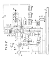
- FIGS 1 to 3 show the general configuration of an embodiment of the ophthalmological measurement apparatus of this invention.
- reference numeral 1 denotes a laser light projection section having a helium-neon or other such laser light source 3.
- the laser beam from the laser light source 3 passes through a lens 4, a movable mirror 5, a lens 6, a prism 7, a beam-splitter 9, a lens 10 and a prism 11 whereby the beam is converged on a prescribed point P in the oculi anterior of the eye E being examined.
- the movable mirror 5 is connected to a mirror drive circuit 30 controlled by a computer 31 constituted by a microprocessor or the like in a configuration that allows the angle of the movable mirror 5 to be changed so as to deflect the laser beam to scan a measurement zone over a prescribed range about a center formed by a point of laser beam convergence P. As described below, this scanning range is set so that it exceeds the range of an aperture formed in a measurement mask.
- the laser light projection section 1 is provided with a white-light source 12 (a halogen lamp), light from which illuminates a slit 14 via a lens 13.
- the light from the slit 14 thus illuminated passes via a slit light shutter 15, the beam splitter 9, the lens 10 and the prism 11 to form a slit image in the vicinity of the point of convergence P in the oculi anterior of the eye E.
- the slit image By illuminating the area around the point of convergence P, the slit image allows the position of the point of convergence P to be readily confirmed when the system is being aligned.
- the width and length of the slit 14 can be adjusted by a slit width adjustment knob 55 and slit length adjustment knob 56 ( Figure 1) to enable the apparatus to be utilized also as a slit-lamp microscope.
- the computer 31 controls the shutter 15 via a drive circuit 34 so that the shutter 15 is open during alignment and closed during measurement of protein concentration in the oculi anterior. This is accomplished by inserting the shutter 15 into, or retracting it from, the corresponding optical system by operating an input device such as a joystick 53 which is equipped with a push-button switch 54 and provided on a base 51.
- an input device such as a joystick 53 which is equipped with a push-button switch 54 and provided on a base 51.
- a light receiving section 2 is provided for receiving scattered light from the vicinity of the point of convergence P and to allow the area to be observed. For this, scattered light from the point of convergence P in the oculi anterior of the eye E under examination passes through a lens 16, is reflected by a semi-transparent mirror 17 and passes, via the lens 18, a photomultiplier shutter 20, a measurement mask 21 and a bandpass filter 35 to impinge on a photomultiplier (P.M.)22 which constitutes the photosensor. Light impinging on the photomultiplier 22 is limited to light passing through an aperture 21a formed in the mask 21, which therefore serves to block extraneous light from other areas.
- the measurement mask 21 (aperture 21a) is provided at a position that is optically conjugate with the point of convergence P, with respect to the light receiving section 2.
- the aperture 21a is rectangular in shape, as can be seen in Figure 6.
- the bandpass filter 35 is provided for allowing only the laser light to pass to the photomultiplier 22, while shutting out the white light from the white-light source 12, which constitutes noise, as much as possible.
- the output from the photomultiplier 22 is passed through an amplifier 23 and input to a counter 33 which counts the intensity of the scattered light detected by the photomultiplier 22 as a pulse count per unit time.
- the count values for each unit time as counted by the counter 33 are stored at specific locations in a memory 32.
- the data thus stored in the memory 32 is arithmetically processed by the computer 31 to compute the appropriateness of the alignment and the protein concentration in the oculi anterior.
- the shutter 20 is provided to protect the photomultiplier 22 and is open only during measurement.Like the shutter 15 it is inserted into, or retracted from, the corresponding optical system by the drive circuit 34 operated in conjunction with the oscillation of the movable mirror 5 by an input device such as the joystick 53 equipped with a push-button switch 54.
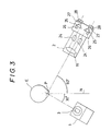
- a microscope system which permits observation around the point of convergence P in the eye. With this configuration, light transmitted through the semi-transparent mirror 17 is observed by an examiner 29 via a lens 24, erect normal prisms 25 and 26, field of vision stop 27 and eyepiece 28. As shown in Figure 3 the microscope is provided with a double eyepiece for binocular viewing. The microscope allows the projected laser beam and the origin of harmful light rays to be observed prior to measuring the protein concentration in the oculi anterior.
- the measurement zone is scanned at a higher frequency during the alignment than the frequency of the measurement scanning, thus permitting alignment by visual observation, and, moreover, the output from the photomultiplier is processed for detecting the presence/absence of weak harmful light rays and thus making it possible for the examiner to know the appropriateness of the alignment.
- the light receiving section 2 is also provided with an alignment index 41 which is illuminated by a light-emitting diode (LED) or other such alignment light source 40.
- the alignment index 41 is located at a position that is conjugate with the mask 21 and with the field of vision stop 27.
- the point of convergence P is conjugate with respect to the mask 21 and field of vision stop 27, and the alignment index 41 is also conjugate with respect to the mask 21 and field of vision stop 27.
- the alignment light source 40 is constituted of an LED that emits light of two colors and is driven by the same driver circuit 34 that drives the shutters 15, 20 so as to emit light of one color when the alignment is appropriate, to emit light of the other color when the alignment is inappropriate and to be turned off during measurement.
- An eye fixation light 57 constituted, in this embodiment, by a light-emitting diode is provided at a position that permits the examiner to fix the patient's eye ( Figure 1).
- the eye fixation light 57 can be turned in the direction indicated by the arrow by means of a linkage 58 to enable it to be adjusted to the optimal position relative to the patient undergoing the eye examination.
- the light selected for the eye fixation light 57 is of a different color than the laser light.
- an input means which in this case is the joystick 53 equipped with a push-button 54.
- This input means can be used for moving optical elements such as the shutters 15 and 20 into and out of the respective optical system as described above, or may be used to switch the alignment light source on and off.
- the laser light projection section 1 and light receiving section 2 can each rotate independently in a horizontal plane about an axis 50.
- a detente mechanism or the like is used to lock the laser light projection section 1 and the light receiving section 2 at an angle of 30 degrees and 90 degrees respectively with respect to the normal of the corneal vertex.
- the apparatus is to be used as a slit-lamp microscope the two sections are unlocked to allow them to rotate freely to view the eye in cross-section.
- a power supply 60 ( Figure 2) is provided for supplying power to the various components and circuitry.
- a lamp 61 indicates when the power supply 60 is on.
- the overall operation of the apparatus thus configured will now be described.
- the patient's head is positioned on a chin rest, the white-light source 12 is switched on and the shutter 15 is opened to project an image of the slit 14 onto the eye E.
- the laser beam from the laser light projection section 1 is converged on the point of convergence P in the eye E, and the mirror driver circuit 30, upon being actuated by an input device such as the push-button switch 54, functions to oscillate the movable mirror 5 so that the laser beam scans the measurement zone at high speed about a center formed by the point of convergence P.
- the photomultiplier shutter 20 is left open during the alignment procedure.
- the scanning width S2 at the measurement area is set to about twice the width S1 of the image of the mask aperture 21a in the eye.
- the scanning frequency used is 50 to 60 Hz, for instance, which is high enough to permit observation of the measurement zone by the human eye without any perception of flicker.
- the alignment light source 40 is switched on to illuminate the alignment index 41.
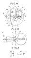
- the image that the examiner will see at this point is shown in Figure 4.
- the point of convergence P is at a position that is conjugate with the mask 21 and the field of vision stop 27, while the alignment index 41 is in a conjugate relationship with the mask 21 and field of vision stop 27.
- the alignment index 41 illuminated by the light source 40 appears to be located at the point of convergence P.
- the movable mirror 5 scans the laser beam 3a over a range that is about twice the width of the image 70 of the aperture 21a.
- H2 is the range of a measurement zone scan sweep by the laser beam 3a and H1 is the length of the aperture image 70 measured along the short side
- H2 is about twice H1.
- F is a point at which there is no movement even during deflection of the laser beam 3a. There is no movement at F because it is conjugate with respect to the axis of oscillation of the reflecting surface of the movable mirror 5, and therefore the oscillation of the movable mirror 5 has no bearing on it.
- the laser beam 3a impinges on the cornea 71 before reaching the point of convergence P and is scattered from the part of the cornea 71 marked A. (Although slit and laser light is actually scattered from two points, the front surface 71b and rear surface 71c of the cornea 71, because of the closeness of the two in the drawing they are shown as a single point A.)
- the laser beam 3a also passes through the point of convergence P and into the crystalline lens 72 where it produces scattered light B.
- light reflected by the surface of the crystalline lens 72 forms an image C on the cornea 71. This harmful light B and C is particularly intense in the case of a prosthetic crystalline lens.
- 73 is the iris.
- a corneal image is formed by scattered light from the exit face of the prism 11. Specifically, as the laser light passes through the prism 11 and converges in the eye, it is scattered at the exit face of the prism, producing secondary light sources that give rise to a spurious image owing to the convex mirror effect of the cornea.
- the above A to D are the main sources of harmful rays.
- the laser beam 3a is made to scan the measurement zone at high speed at the same scan width (H2) used for measurement scanning. Since this high-speed scanning of the measurement zone is performed at a frequency such as 50 Hz or 60 Hz that is above the flicker perception threshold of the human eye, it becomes possible to simulate the harmful light rays arising during actual measurement, which facilitates the identification and elimination of the harmful rays.
- the elimination of the harmful light rays A to D is realized by aligning the apparatus so that the rays do not come within the aperture image 70.
- these harmful light rays behave like scattered light sources with low directivity and illuminate the surrounding area, in order to ensure that only scattered light from proteins in the oculi anterior is received, the system should be aligned to achieve a maximum separation of the aperture image 70 from the harmful light sources to optimize measurement precision.
- the system is aligned in this manner, it becomes possible to receive solely the light scattered by the protein in the oculi anterior and thus to increase the accuracy of the measurement.
- stronger harmful rays can be can be easily discerned by visual observation, the secondary and tertiary harmful rays are extremely weak and virtually impossible to discern visually.
- the output of the photomultiplier is processed during alignment in the same manner as during measurement (to be described below) and it is judged that the alignment is such as to eliminate the influence of harmful rays when, as shown in Figure 7, M1 and M3 are smaller than M2 and, moreover, M1 and M3 are substantially equal.
- the drive circuit 34 changes the color of the light emitted by the light source 40, thus indicating to the examiner that the alignment is proper so that he may proceed with the measurement.
- the light source 40 for illuminating the alignment index 41 there can be used a monochrome LED which is made to flash at a low frequency (e.g. 1 - 2 Hz) when the alignment is inappropriate, to flash at progressively higher (but visibly perceptible) frequencies as the alignment improves and to become constantly on when the alignment becomes proper for measurement.
- a monochrome LED which is made to flash at a low frequency (e.g. 1 - 2 Hz) when the alignment is inappropriate, to flash at progressively higher (but visibly perceptible) frequencies as the alignment improves and to become constantly on when the alignment becomes proper for measurement.
- the examiner can be informed of the appropriateness of the alignment by a synthesized voice or the like.
- the mask aperture image 70 can be readily distinguished from the harmful light ray sources A to D.
- the aperture image 70 in the eye should have a width that is about one-thirtieth to one-fifteenth the diameter of the dilated pupil and a length that is one-eighth to one-quarter the depth of the oculi anterior.
- the system mode is changed to measurement.
- pressing the switch 54 of the joystick 53 turns off the alignment light source 40, causes scanning of the measurement area to be conducted at a different frequency than during alignment, and enables scattered laser light to be received by the light receiving section 2 and measured to determine the protein concentration in the oculi anterior.
- the projection section 1 projects the beam of laser light at the point of convergence P of the eye E under examination and light scattering from the area around the point of convergence P is received by the photomultiplier 22 of the light receiving section 2.
- the movable mirror 5 is oscillated by the mirror drive circuit 30 in the direction shown by the arrow to scan the measurement zone with point P at the center.
- the laser beam 3a is deflected at a lower frequency setting of about 2 Hz, which makes it possible to secure a signal adequate for obtaining a measurement result with a good signal/noise ratio (Figure 6).
- the photomultiplier 22 receives incident scattered laser light via the aperture 21a and detects the intensity of the light scattered by protein particles in the measurement zone of the oculi anterior.
- the scattered light intensity is converted to a corresponding pulse train and counted by the counter 33 as a pulse count per unit time period, and the count values per unit time are stored at specific locations in the memory 32.
- the count values stored in the memory 32 become as shown in Figure 7 when arranged time sequence.
- t1 and t3 are intervals when the incident laser beam 3a is not within the aperture 21a and indicate the inclusion of noise components produced by intra-ocular reflection or scattering of light other than the aforesaid harmful rays, or the ambient brightness of the measurement environment.
- M1 and M3 are taken as average values of counts in the memory 32 for intervals t1 and t3. Also included as noise in M1 and M3 is the dark current of the photomultiplier 27. These noise components fluctuate from measurement to measurement.
- Interval t2 is the interval during which the scattered laser light enters via the aperture 21a and includes signal components corresponding to the protein concentration in the oculi anterior, noise components caused by reflection and scattering, noise components caused by the ambient brightness, and the photomultiplier dark current.
- M2 is the average of the count values stored in the memory 32 during this interval.
- the computer 31 deducts the mean value of M1 and M3 from the value M2 stored in the memory 32 to extract the effective component, from which it computes the protein concentration in the oculi anterior. If the system has been properly aligned, the values of M1 and M3 will be about the same. If the data were only obtained by measurement during the interval t2 the signal/noise ratio would be poor and the variance large with a corresponding degradation in reproducibility ( Figure 8a) but, as shown by Figure 8b, in accordance with this invention the signal/noise ratio is improved by deducting the noise component, which also increases the dynamic range and improves the reproducibility.
- high-speed laser beam scanning of the measurement zone is implemented during alignment using a scanning width that is the same as the scanning width used for the measurement.
- the output of the photomultiplier during alignment can be processed for providing an indication showing the appropriateness of the alignment. This enables the apparatus to be aligned so that the harmful light rays do not come within the measurement mask aperture, thereby enabling measurement to be conducted under optimum conditions.
Applications Claiming Priority (2)
| Application Number | Priority Date | Filing Date | Title |
|---|---|---|---|
| JP61178/90 | 1990-03-14 | ||
| JP2061178A JP2854657B2 (ja) | 1990-03-14 | 1990-03-14 | 眼科測定装置 |
Publications (2)
| Publication Number | Publication Date |
|---|---|
| EP0447047A2 true EP0447047A2 (fr) | 1991-09-18 |
| EP0447047A3 EP0447047A3 (en) | 1991-11-21 |
Family
ID=13163644
Family Applications (1)
| Application Number | Title | Priority Date | Filing Date |
|---|---|---|---|
| EP19910301420 Ceased EP0447047A3 (en) | 1990-03-14 | 1991-02-22 | Ophthalmological measurement apparatus |
Country Status (3)
| Country | Link |
|---|---|
| US (1) | US5202709A (fr) |
| EP (1) | EP0447047A3 (fr) |
| JP (1) | JP2854657B2 (fr) |
Families Citing this family (17)
| Publication number | Priority date | Publication date | Assignee | Title |
|---|---|---|---|---|
| JP3483922B2 (ja) * | 1993-12-24 | 2004-01-06 | 興和株式会社 | 眼科測定装置 |
| US5980513A (en) | 1994-04-25 | 1999-11-09 | Autonomous Technologies Corp. | Laser beam delivery and eye tracking system |
| JP3608854B2 (ja) * | 1995-09-22 | 2005-01-12 | 興和株式会社 | 眼科測定装置 |
| US20010041884A1 (en) * | 1996-11-25 | 2001-11-15 | Frey Rudolph W. | Method for determining and correcting vision |
| US6271914B1 (en) | 1996-11-25 | 2001-08-07 | Autonomous Technologies Corporation | Objective measurement and correction of optical systems using wavefront analysis |
| US5777719A (en) | 1996-12-23 | 1998-07-07 | University Of Rochester | Method and apparatus for improving vision and the resolution of retinal images |
| CA2338060C (fr) | 1998-08-19 | 2005-03-15 | Autonomous Technologies Corporation | Dispositif de mesure des defauts de la vision chez l'homme et methode afferente |
| US6598975B2 (en) * | 1998-08-19 | 2003-07-29 | Alcon, Inc. | Apparatus and method for measuring vision defects of a human eye |
| US6199986B1 (en) | 1999-10-21 | 2001-03-13 | University Of Rochester | Rapid, automatic measurement of the eye's wave aberration |
| WO2001078585A2 (fr) | 2000-04-19 | 2001-10-25 | Alcon Universal Ltd. | Capteur de front d'onde permettant d'effectuer une mesure objective d'un systeme optique, et procedes associes |
| US6460997B1 (en) | 2000-05-08 | 2002-10-08 | Alcon Universal Ltd. | Apparatus and method for objective measurements of optical systems using wavefront analysis |
| US6685317B2 (en) | 2000-06-13 | 2004-02-03 | Massie Research Laboratories, Inc. | Digital eye camera |
| JP4408640B2 (ja) | 2003-03-17 | 2010-02-03 | 興和株式会社 | 眼科測定装置 |
| JP4542350B2 (ja) | 2004-02-13 | 2010-09-15 | 興和株式会社 | 前眼部の測定装置 |
| JP4863676B2 (ja) * | 2005-09-22 | 2012-01-25 | 興和株式会社 | 眼科装置 |
| USD753309S1 (en) * | 2013-09-09 | 2016-04-05 | Kowa Company, Ltd. | Slit lamp |
| JP1529228S (fr) * | 2014-10-30 | 2015-07-21 |
Citations (5)
| Publication number | Priority date | Publication date | Assignee | Title |
|---|---|---|---|---|
| US4702576A (en) * | 1985-09-27 | 1987-10-27 | Cambridge Instruments Inc. | Ocular scattering analyzer |
| EP0279589A1 (fr) * | 1987-02-17 | 1988-08-24 | Eye Research Institute Of Retina Foundation | Alignement/stabilisateur pour le fond d'oeil |
| EP0295764A1 (fr) * | 1987-04-09 | 1988-12-21 | Kowa Co. Ltd. | Dispositif de détection de maladies des yeux |
| EP0380260A2 (fr) * | 1989-01-23 | 1990-08-01 | Kowa Company Ltd. | Dispositif de mesure destiné à l'examen ophtalmologique |
| EP0405708A2 (fr) * | 1989-06-29 | 1991-01-02 | Kowa Company Ltd. | Appareil de mesure ophtalmique |
Family Cites Families (1)
| Publication number | Priority date | Publication date | Assignee | Title |
|---|---|---|---|---|
| DE3422144A1 (de) * | 1984-06-14 | 1985-12-19 | Josef Prof. Dr. 6900 Heidelberg Bille | Geraet zur darstellung flaechenhafter bereiche des menschlichen auges |
-
1990
- 1990-03-14 JP JP2061178A patent/JP2854657B2/ja not_active Expired - Lifetime
-
1991
- 1991-02-22 EP EP19910301420 patent/EP0447047A3/en not_active Ceased
- 1991-02-28 US US07/662,786 patent/US5202709A/en not_active Expired - Lifetime
Patent Citations (5)
| Publication number | Priority date | Publication date | Assignee | Title |
|---|---|---|---|---|
| US4702576A (en) * | 1985-09-27 | 1987-10-27 | Cambridge Instruments Inc. | Ocular scattering analyzer |
| EP0279589A1 (fr) * | 1987-02-17 | 1988-08-24 | Eye Research Institute Of Retina Foundation | Alignement/stabilisateur pour le fond d'oeil |
| EP0295764A1 (fr) * | 1987-04-09 | 1988-12-21 | Kowa Co. Ltd. | Dispositif de détection de maladies des yeux |
| EP0380260A2 (fr) * | 1989-01-23 | 1990-08-01 | Kowa Company Ltd. | Dispositif de mesure destiné à l'examen ophtalmologique |
| EP0405708A2 (fr) * | 1989-06-29 | 1991-01-02 | Kowa Company Ltd. | Appareil de mesure ophtalmique |
Also Published As
| Publication number | Publication date |
|---|---|
| JPH03264044A (ja) | 1991-11-25 |
| US5202709A (en) | 1993-04-13 |
| JP2854657B2 (ja) | 1999-02-03 |
| EP0447047A3 (en) | 1991-11-21 |
Similar Documents
| Publication | Publication Date | Title |
|---|---|---|
| US5202709A (en) | Ophthalmological alignment and measurement apparatus | |
| US4900145A (en) | Ophthalmic disease detection apparatus | |
| US5644642A (en) | Gaze tracking using optical coherence tomography | |
| US5184157A (en) | Ophthalmic measurement apparatus | |
| US5202708A (en) | Apparatus for photographic retroillumination image on eyeground | |
| US4227780A (en) | Eye examining instrument | |
| US6520640B1 (en) | Acquiring, analyzing and imaging three-dimensional retinal data | |
| US4950068A (en) | Ophthalmic disease detection apparatus | |
| US5807273A (en) | Ophthalmic apparatus | |
| EP0292216B1 (fr) | Dispositif de détection de maladies oculaires | |
| US5141304A (en) | Ophthalmological measurement apparatus having sensitivity error correction | |
| US5120123A (en) | Ophthalmic measuring method and apparatus | |
| US5000562A (en) | Ophthalmic disease detection method and apparatus | |
| EP0299710B1 (fr) | Dispositif destiné au diagnostic de maladies oculaires | |
| US6607272B1 (en) | Retinal blood flow measuring apparatus using a laser beam | |
| EP0380260A2 (fr) | Dispositif de mesure destiné à l'examen ophtalmologique | |
| US5013146A (en) | Opthalmological measurement apparatus | |
| US4988184A (en) | Ophthalmic disease detection apparatus | |
| JP2005312501A (ja) | 眼屈折力測定装置 | |
| JPH0654807A (ja) | 眼科装置 | |
| JP4235504B2 (ja) | 眼科測定装置 | |
| JPH11290274A (ja) | 検眼装置 | |
| JPH012624A (ja) | 眼科測定装置 | |
| JP2003024278A (ja) | 角膜形状測定装置 |
Legal Events
| Date | Code | Title | Description |
|---|---|---|---|
| PUAI | Public reference made under article 153(3) epc to a published international application that has entered the european phase |
Free format text: ORIGINAL CODE: 0009012 |
|
| AK | Designated contracting states |
Kind code of ref document: A2 Designated state(s): CH DE FR GB IT LI |
|
| PUAL | Search report despatched |
Free format text: ORIGINAL CODE: 0009013 |
|
| AK | Designated contracting states |
Kind code of ref document: A3 Designated state(s): CH DE FR GB IT LI |
|
| 17P | Request for examination filed |
Effective date: 19920506 |
|
| 17Q | First examination report despatched |
Effective date: 19931208 |
|
| STAA | Information on the status of an ep patent application or granted ep patent |
Free format text: STATUS: THE APPLICATION HAS BEEN REFUSED |
|
| 18R | Application refused |
Effective date: 19941118 |