EP0446856A2 - Elektronisches Gerät mit Tonausgangssignal - Google Patents
Elektronisches Gerät mit Tonausgangssignal Download PDFInfo
- Publication number
- EP0446856A2 EP0446856A2 EP91103731A EP91103731A EP0446856A2 EP 0446856 A2 EP0446856 A2 EP 0446856A2 EP 91103731 A EP91103731 A EP 91103731A EP 91103731 A EP91103731 A EP 91103731A EP 0446856 A2 EP0446856 A2 EP 0446856A2
- Authority
- EP
- European Patent Office
- Prior art keywords
- input
- data
- sound
- key
- braille
- Prior art date
- Legal status (The legal status is an assumption and is not a legal conclusion. Google has not performed a legal analysis and makes no representation as to the accuracy of the status listed.)
- Withdrawn
Links
Images


Classifications
-
- G—PHYSICS
- G09—EDUCATION; CRYPTOGRAPHY; DISPLAY; ADVERTISING; SEALS
- G09B—EDUCATIONAL OR DEMONSTRATION APPLIANCES; APPLIANCES FOR TEACHING, OR COMMUNICATING WITH, THE BLIND, DEAF OR MUTE; MODELS; PLANETARIA; GLOBES; MAPS; DIAGRAMS
- G09B21/00—Teaching, or communicating with, the blind, deaf or mute
- G09B21/02—Devices for Braille writing
- G09B21/025—Devices for Braille writing wherein one tactile input is associated to a single finger
-
- G—PHYSICS
- G09—EDUCATION; CRYPTOGRAPHY; DISPLAY; ADVERTISING; SEALS
- G09B—EDUCATIONAL OR DEMONSTRATION APPLIANCES; APPLIANCES FOR TEACHING, OR COMMUNICATING WITH, THE BLIND, DEAF OR MUTE; MODELS; PLANETARIA; GLOBES; MAPS; DIAGRAMS
- G09B21/00—Teaching, or communicating with, the blind, deaf or mute
- G09B21/001—Teaching or communicating with blind persons
- G09B21/006—Teaching or communicating with blind persons using audible presentation of the information
-
- G—PHYSICS
- G09—EDUCATION; CRYPTOGRAPHY; DISPLAY; ADVERTISING; SEALS
- G09B—EDUCATIONAL OR DEMONSTRATION APPLIANCES; APPLIANCES FOR TEACHING, OR COMMUNICATING WITH, THE BLIND, DEAF OR MUTE; MODELS; PLANETARIA; GLOBES; MAPS; DIAGRAMS
- G09B21/00—Teaching, or communicating with, the blind, deaf or mute
- G09B21/02—Devices for Braille writing
Definitions
- the present invention relates to an electronic apparatus and, more particularly, to an electronic apparatus which has key input means corresponding to each element of a predetermined braille pattern and stores and inputs or outputs information which was input from the key input means.
- the second object of the invention is to convert braille information which was stored by a key input into a buzzer sound and generate.
- the third object of the invention is to provide an electronic apparatus in which braille information which is being generated by a key input is compared with braille information stored in memory means and when they coincide, the coincidence can be confirmed by a sound output.
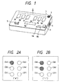
- Fig. 1 is a perspective view showing a schematic construction of an electronic apparatus to which the invention was applied.
- reference numeral 1 denotes an apparatus main body; 2a to 2f input keys for a braille input; 3 a power switch; 4 an input/output (I/O) interface; 5 a memory switch; 6 a cursor key comprising a forward key 6a and a back key 6b; and 7 a speaker.
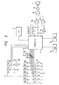
- Fig. 2 shows expressions of characters " P" (which reads “a") and " T " (which reads "i”) according to braille points.
- the braille expresses a character by a pattern of projections (points) of two columns and three rows as a matrix of vertical and lateral points.
- the elements (points) shown by hatched regions are expressed as projections.
- the input keys 2a to 2f in Fig. 1 correspond to the elements of six braille points as mentioned above, respectively.
- the corresponding relation between each point and the input key is as shown in the parentheses in Figs. 2A and 2B.
- the respective points are rearranged in a predetermined direction.
- the input key 2a is first pressed and a finger is removed from the input key 2a and both of the input keys 2a and 2b are then simultaneously pressed.
- a sentence is input.
- the memory switch 5 is inclined to the left to set a memory mode.
- a file name is input by using the desired input keys 2a to 2f while depressing the space key 2g.
- the file name has a meaning similar to a data file in a word processor or the like. After the finger was removed from the space key 2g, the sentence is stored every key input into an RAM which was assigned every file name.
- the memory switch 5 is inclined to the right to set a reading mode and the back key 6b is pressed a number of times corresponding to the number of characters until a position of a character to be confirmed.
- the memory switch 5 is first inclined to the right to set the reading mode and, after that, the back key 6b is pressed twice and a search point is returned to data to be confirmed in the RAM.
- the input data of the input keys 2a and 2c has been stored in the RAM and is expressed by binary numbers of "101000".
- sounds are generated such that "bee, pi, bee, pi, pi, pi” (that is, “bee” corresponds to the binary number "1” and "pi” corresponds to the binary number "0").
- the blind can confirm the input data by listening to such sounds.
- the memory switch 5 is inclined to the left to set the memory mode and a key input is again executed.
- the memory switch 5 is set to the reading mode and a desired file name to be generated is input by the input keys 2a to 2f while depressing the space key 2g.
- the data in the RAM corresponding to the input file name is generated from the 1/0 interface 4.
- the content of the data can be again read by connecting the 1/0 interface 4 to a braille display, a braille word processor with a braille display, or the like.
- Fig. 3 is a block diagram according to the first embodiment of the invention showing the construction of the apparatus of Fig. 1.
- a control section of the apparatus comprises a controller 11 which is constructed by a one-chip microprocessor or the like. Outputs of the keys in Fig. 1 are supplied to the controller 11.
- the input keys 2a to 2f and the space key 2g are suspended by pull-up resistors 10a to 10g.
- a signal indicative of "0" or "1" is supplied to the controller 11 in accordance with the presence or absence of the key depression.
- Reference numeral 18 denotes a 7-input AND gate to generate signals to inform data reading timings to the controller.
- the controller reads the data at a timing after the elapse of hundreds of msec from a time point when an output of the 7- input AND gate 18 was changed from "1" " to "0".
- the memory switch 5, forward key 6a, and back key 6b have also similarly been pulled up. Data of " 1 " or "0" is sent to the controller and used to discriminate the operating mode and to move a cursor.
- Reference numeral 12 denotes an ROM.
- a program which is used in the controller, which will be explained hereinlater, is stored in the ROM 12.
- Reference numeral 13 indicates an RAM.
- the key input data is stored into or extracted from the RAM 13 in accordance with the key operation.
- the I/O interface 4 is used to supply the data in the RAM 13 to the outside.
- Reference numeral 14 denotes an inverter; 15a and 15b NAND gates; 16 an AND gate; 17 an amplifier; and 7 the speaker to generate and express the content of the RAM 13 by a high or low tone of the sound.
- the data which was read out of the RAM 13 is stored into a shift register in the controller and is sequentially supplied to the NAND gate 15a or to the NAND gate 15b through the inverter 14.
- Pulses of a different frequency to drive the speaker 7 are supplied to the other terminals of the NAND gates 15a and 15b.
- the NAND gate 15a and the AND gate 16 are turned on, so that a sound of a high tone is generated.
- the data in the shift register is set to "0”
- a sound of a low tone is generated via the NAND gate 15b and the AND gate 16.
- step S40 when the power source is turned on, the controller is initialized in step S40 in Fig. 4 and, for instance, a port is set and pulses to ring a buzzer are formed.
- step S41 a check is made to see if the memory mode has been set or not.
- the apparatus waits for a key input in step S42. If a key input has been performed, a check is made in step S43 to see if the key input has been made to set a file name or not.
- step S43 The discrimination in step S43 is performed by checking whether the space key 2g has simultaneously been depressed or not.
- an address in the RAM 13 corresponding to the file name is set in step S44.
- the subsequent key input data is sequentially input from the above address.
- step S43 If the file name is not input in step S43, this means that the address has already been set, so that step S45 follows.
- step S45 and S46 the back key 6b and the forward key 6a have been depressed or not. If they have been depressed, the address is increased in step S49 or is decreased in step S410. In step S411, the value of the address in the RAM 13 is loaded into the shift register.
- the content of the shift register is generated in step S412, thereby generating a sound of a high or low tone as shown in Fig. 3 mentioned above.
- step S413 the data in the shift register is shifted. Processes of a loop in steps S412, S413, and S414 are executed until the data generation is finished in step S414. After completion of the data generation, the processing routine is returned to step S42.
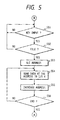
- step S41 If the reading mode has been set in step S41, the processing routine advances to step S51 in Fig. 5. The processes of a loop in steps S51 and S52 are repeated until the file name is input. If the file name has been input, the address corresponding to the file name is set in step S53. The data is generated to the I/O interface 4 in steps S54, S55, and S56.
- the input data can be confirmed without using a braille display.
- the content of the RAM 13 has been informed by a buzzer sound upon confirmation. However, it can be also informed by a synthetic voice sound. A tone of buzzer sound can be also freely changed by making a pulse width variable.
- the key input means corresponding to each element of a predetermined braille pattern
- the memory means for storing braille data which was input from the key input means
- the means for generating the input data stored in the memory means as a sound Therefore, there is no need to use large, complicated, and expensive braille output means. It is possible to provide an excellent electronic apparatus which has an excellent portability and in which the user can confirm the braille data which was input and stored.
- Fig. 1 regarding the electronic apparatus of the invention, in the case where the user desires to confirm the character which has already been input during an inputting operation of a sentence in a state in which the memory switch 5 was set to the memory mode, the memory switch 5 is inclined to the right to set the reading mode and the back key 6b is depressed only a number of times corresponding to the number of characters until a location of data to be confirmed in the memory.
- the memory switch 5 is first set to the reading mode and the back key 6b is depressed twice and a search position is returned to the data to be confirmed in the RAM.
- the memory switch 5 is set to the reading mode and file name to be generated is input by pressing the input keys 2a to 2f while depressing the space key 2g. After the space key was released, the data in the RAM corresponding to the input file name is generated from the 1/0 interface 4.
- the data content can be read again by connecting the I/O interface 4 to a braille display, a braille word processor with a braille display, or the like.
- Fig. 6 is a block diagram of the second embodiment of the invention showing another construction of the apparatus of Fig. 1.
- the input keys 2a to 2f and the space key 2g are suspended by the pull-up resistors 10a to 10g.
- a signal of "0" or "1" " is input to the controller in accordance with the presence or absence of the key depression.
- Reference numeral 18 denotes the 7-input AND gate to generate signals for informing data reading timings to the controller.
- the controller reads the data from a timing after the elapse of hundreds of 100 msec from a time point when outputs of the AND gate 18 were changed from "1" " to "0".
- the memory switch 5, forward key 6a, and back key 6b have also similarly been pulled up.
- the data of "1" " or "0” is sent to the controller and is used to discriminate the operating mode and to move a cursor.
- a software program which is used by the controller has been stored in the ROM 12.
- the key input data is stored into or read out from the RAM 13 in accordance with the key operations.
- the 1/0 interface 4 is used to output the data in the RAM 13 to the outside.
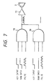
- Reference numerals 19a to 19g denote data comparators comprising 3-input AND gates.
- the input key is depressed when the data in the RAM is confirmed. For instance, when the input key 2a is depressed, a signal “1” is supplied to one of three inputs of the AND gate 19a, while a signal “0” is supplied when the input key 2a is released. Similarly, when the input key 2b is depressed, a signal “1” is supplied to one input of the AND of the AND gates 19b to 19g, while a signal “0” is supplied when the input key 2b is released.
- the inverted data of the data in the RAM is supplied to the other one of the three inputs. For instance, assuming that the data in the RAM 13 is set to "0101111” " in accordance with the order of the input keys 2a to 2g, a signal “1” " is supplied to the AND gates 19a and 19c.
- a pulse waveform to vibrate a piezoelectric buzzer or the like is supplied to the other remaining one input.
- the vibration is subsequently amplified by the amplifier 17 and a buzzer sound is generated from the speaker 7.
- Fig. 7 shows the relations between three inputs and the AND gates 19.
- step S40 When the power source is turned on, the controller is first initialized in step S40 in Fig. 8 and, for example, a port is set and pulses to ring a buzzer are made.
- step S41 a check is made to see if the memory mode has been set or not. If the memory mode has been set, the apparatus waits for a key input in step S42.
- step S43 If a key input has been performed, a check is made in step S43 to see if the key input to set a file name has been performed or not by discriminating whether the space key 2g has simultaneously been depressed or not.
- step S44 the address in the RAM 13 corresponding to the file name is set in step S44.
- the subsequent key input data is sequentially input from the above address. If the file name is not input in step S43, this means that the address has already been set, so that the processing routine advances to step S45.
- steps S45 and S47 checks are made to see if the back key 6b and the forward key 6a have been depressed or not. If the back key 6b and the forward key 6a have been depressed, the address is decreased in step S46 or is increased in step S48.
- step S45 and S47 If the keys 6b and 6a are not depressed in steps S45 and S47, the key input data is stored into the relevant address in the RAM in step S49.
- the address in the RAM is increased in step S410. Then, the processing routine is returned to the key input step S42 and similar processes are continued. The data is stored into the RAM.
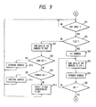
- step S41 If the reading mode has been set in step S41, the processing routine advances to @ in Fig. 9.
- the apparatus waits for a key input in step S51. If the key input has been performed, a check is made in step S52 to see if the key input indicates a file name or not. If YES, the address corresponding to the file name is set in step S53. In step S54, the content of the RAM 13 is transmitted to the I/O interface 4. The address is increased in' step S55.
- step S56 A check is made in step S56 to see if the transmission has been finished or not. If YES, the processing routine advances to (E) in Fig. 8. If the transmission is not finished yet in step S56, the processing routine is returned to step S54 and the processes in steps S54 and S55 are repeated until the data transmission is finished.
- step S52 If the file name is not input in step S52, the content of the address in the RAM is supplied to the port in step S57. This output signal is input to the 3-input AND gates 19a to 19g in Fig. 7.
- steps S58 and S59 checks are made to see if the back key 6b or the forward key 6a has been depressed or not. If either one of the back key 6b and the forward key 6a has been depressed, the address is decreased in step S510 or is increased in step S511.
- a signal "1" " is output to the port corresponding to the input key in step S512 and is supplied to another one of three ports of the 3-input AND gate.
- the data which is being input or edited can be confirmed without using a braille display and the electronic apparatus having an excellent portability can he provided.
- the small electronic apparatus having a use efficiency similar to an electronic notebook which is used by a user of a normal eyesight can be provided.
- the key input means corresponding to each element of a predetermined braille pattern; the memory means for storing braille data which was input from the key input means; the means for comparing the input data which was input from the key input means and the input data stored in the memory means; and the means for generating the information indicative of the result of the comparison of the comparing means as sound data. Therefore, it is possible to provide an electronic apparatus having excellent portability and operability in which there is no need to provide braille output means and by comparing the braille data which is being input and the stored braille data, the result of the comparison can be confirmed by a sound output, and the apparatus can be reduced in size and weight.
- a sound output electronic apparatus of the invention comprises: key input means corresponding to elements of a predetermined braille pattern; memory means for storing braille data which was input from the key input means; and means for generating the input data stored in the memory means as sounds.
- the data of the braille data which was key input and stored can be recognized by sound information.
- the braille data which is being input is compared with the braille data stored to see if they coincide or not.
- the comparison result can be recognized by a sound output.
Landscapes
- Engineering & Computer Science (AREA)
- Health & Medical Sciences (AREA)
- Audiology, Speech & Language Pathology (AREA)
- General Health & Medical Sciences (AREA)
- Business, Economics & Management (AREA)
- Physics & Mathematics (AREA)
- Educational Administration (AREA)
- Educational Technology (AREA)
- General Physics & Mathematics (AREA)
- Theoretical Computer Science (AREA)
- Input From Keyboards Or The Like (AREA)
Applications Claiming Priority (4)
| Application Number | Priority Date | Filing Date | Title |
|---|---|---|---|
| JP2059853A JPH03262032A (ja) | 1990-03-13 | 1990-03-13 | 電子機器 |
| JP59854/90 | 1990-03-13 | ||
| JP59853/90 | 1990-03-13 | ||
| JP2059854A JPH03261574A (ja) | 1990-03-13 | 1990-03-13 | 電子機器 |
Publications (2)
| Publication Number | Publication Date |
|---|---|
| EP0446856A2 true EP0446856A2 (de) | 1991-09-18 |
| EP0446856A3 EP0446856A3 (en) | 1993-06-23 |
Family
ID=26400929
Family Applications (1)
| Application Number | Title | Priority Date | Filing Date |
|---|---|---|---|
| EP19910103731 Withdrawn EP0446856A3 (en) | 1990-03-13 | 1991-03-12 | Sound output electronic apparatus |
Country Status (2)
| Country | Link |
|---|---|
| US (1) | US5154614A (de) |
| EP (1) | EP0446856A3 (de) |
Cited By (3)
| Publication number | Priority date | Publication date | Assignee | Title |
|---|---|---|---|---|
| EP0812094A1 (de) * | 1996-06-07 | 1997-12-10 | Deutsche Telekom AG | Telekommunikationsendegerät |
| ES2366509A1 (es) * | 2008-12-22 | 2011-10-21 | Universidad De Zaragoza | Dispositivo electrónico para la enseñanza y el aprendizaje de la escritura de caracteres en código braille. |
| EP3407108A4 (de) * | 2016-01-21 | 2019-08-28 | Universidad Católica De La Santísima Concepción | Vorrichtung zum schreiben in braille und/oder in audiomorsezeichen für nutzer mit sehstörungen und und/oder motorischen störungen |
Families Citing this family (15)
| Publication number | Priority date | Publication date | Assignee | Title |
|---|---|---|---|---|
| JP2666202B2 (ja) * | 1991-09-11 | 1997-10-22 | キヤノン株式会社 | 障害者用意志伝達装置 |
| US5674076A (en) * | 1995-02-14 | 1997-10-07 | Serenity Productions, Inc. | Hand-held sound generating device |
| US6015224A (en) * | 1996-03-13 | 2000-01-18 | Greenstein; Bonnie | Calculator |
| CN1231827C (zh) * | 2001-04-12 | 2005-12-14 | 丁勇皙 | 基于布莱叶盲文点字法的多用途可视语言装置及方法 |
| RU2223551C2 (ru) * | 2001-08-16 | 2004-02-10 | Федеральное государственное унитарное предприятие "Калужский научно-исследовательский институт телемеханических устройств" | Способ представления звуковыми сигналами информации в коде брайля |
| US20050084828A1 (en) * | 2003-10-21 | 2005-04-21 | The University Of North Carolina At Chapel Hill | Apparatus and method for braille instruction |
| US7403191B2 (en) * | 2004-01-28 | 2008-07-22 | Microsoft Corporation | Tactile overlay for an imaging display |
| CA2460943A1 (en) * | 2004-03-16 | 2005-09-16 | Unknown | Pocket size computers |
| US20060020470A1 (en) * | 2004-07-20 | 2006-01-26 | Glen Dobbs | Interactive speech synthesizer for enabling people who cannot talk but who are familiar with use of picture exchange communication to autonomously communicate using verbal language |
| US9105196B2 (en) | 2004-07-20 | 2015-08-11 | Proxtalker.Com, Llc | Method and system for autonomous teaching of braille |
| US9111463B2 (en) * | 2004-07-20 | 2015-08-18 | Proxtalker.Com, Llc | Interactive speech synthesizer for enabling people who cannot talk but who are familiar with use of anonym moveable picture communication to autonomously communicate using verbal language |
| US20080176201A1 (en) * | 2006-09-20 | 2008-07-24 | Technologies Humanware Canada Inc. | User interface for an audio book player |
| USD766240S1 (en) * | 2014-05-28 | 2016-09-13 | INSIDE VISION (société par actions simplifiée) | Touch pad for visually impaired or blind people |
| USD837203S1 (en) | 2015-05-20 | 2019-01-01 | INSIDE VISION (société par actions simplifiée) | Tactile pad |
| US12239922B1 (en) * | 2024-07-11 | 2025-03-04 | Chase Joliet | Children's toy |
Family Cites Families (18)
| Publication number | Priority date | Publication date | Assignee | Title |
|---|---|---|---|---|
| US3255537A (en) * | 1962-12-28 | 1966-06-14 | Emmett R Salzberg | Teaching machine |
| US3371321A (en) * | 1965-04-15 | 1968-02-27 | Ibm | Tutorial system |
| US3341950A (en) * | 1965-07-07 | 1967-09-19 | Sperry Rand Corp | Braille reading device |
| US3628257A (en) * | 1970-04-09 | 1971-12-21 | Bio Dynamics Inc | Braille dictionary |
| US3851745A (en) * | 1970-06-29 | 1974-12-03 | Nippon Typewriter | Electric braille recording and reproducing system |
| US3883146A (en) * | 1973-04-04 | 1975-05-13 | Education Eng Associates | Hand-held playback device, system and method |
| US4467321A (en) * | 1982-04-30 | 1984-08-21 | Volnak William M | Chording keyboard for generating binary data |
| US4507088A (en) * | 1982-09-08 | 1985-03-26 | Norman Wilson | Deciphering apparatus |
| GB8315630D0 (en) * | 1983-06-07 | 1983-07-13 | Pathway Communications Ltd | Electronic memory devices for blind |
| GB2141274B (en) * | 1983-06-07 | 1986-04-09 | Pathway Communications Ltd | Electronic memory devices for the blind |
| US4831218A (en) * | 1984-09-28 | 1989-05-16 | Binagraphics, Inc. | Universal binary keyboard system |
| DE3527065A1 (de) * | 1985-07-29 | 1987-02-05 | Werner Prof Dr Boldt | Verfahren zur taktilen darstellung der gliederungsstruktur von text- und grafik-seiten im zusammenhang mit der zeilenweisen ausgabe des textes in blindenschrift oder synth. sprache |
| DE3607549A1 (de) * | 1985-11-18 | 1987-05-21 | Papenmeier Friedrich Horst | Informationsabnahmesystem fuer eine datenverarbeitungsanlage |
| AT386335B (de) * | 1986-06-19 | 1988-08-10 | Siemens Ag Oesterreich | Als datenendgeraet ausgebildetes kommunikationsgeraet fuer blinde |
| US4881900A (en) * | 1986-07-23 | 1989-11-21 | Canon Kabushiki Kaisha | Sensing display apparatus of image pattern |
| NL8700164A (nl) * | 1987-01-23 | 1988-08-16 | Alva | Werkstation, voorzien van een brailleleesregel. |
| FR2612312B1 (fr) * | 1987-03-11 | 1992-01-03 | Inst Nat Sante Rech Med | Composant audio-numerique et tactile et dispositif informatique portable en comportant application |
| GB8801309D0 (en) * | 1988-01-21 | 1988-02-17 | British Telecomm | Electronic vibrational display |
-
1991
- 1991-03-12 EP EP19910103731 patent/EP0446856A3/en not_active Withdrawn
- 1991-03-13 US US07/669,187 patent/US5154614A/en not_active Expired - Lifetime
Cited By (3)
| Publication number | Priority date | Publication date | Assignee | Title |
|---|---|---|---|---|
| EP0812094A1 (de) * | 1996-06-07 | 1997-12-10 | Deutsche Telekom AG | Telekommunikationsendegerät |
| ES2366509A1 (es) * | 2008-12-22 | 2011-10-21 | Universidad De Zaragoza | Dispositivo electrónico para la enseñanza y el aprendizaje de la escritura de caracteres en código braille. |
| EP3407108A4 (de) * | 2016-01-21 | 2019-08-28 | Universidad Católica De La Santísima Concepción | Vorrichtung zum schreiben in braille und/oder in audiomorsezeichen für nutzer mit sehstörungen und und/oder motorischen störungen |
Also Published As
| Publication number | Publication date |
|---|---|
| EP0446856A3 (en) | 1993-06-23 |
| US5154614A (en) | 1992-10-13 |
Similar Documents
| Publication | Publication Date | Title |
|---|---|---|
| US5154614A (en) | Sound output electronic apparatus | |
| US5229763A (en) | Remote controller with learning function | |
| JPH05504432A (ja) | 視覚指示器を迅速に選択する可予測走査入力システム | |
| EP0390169B1 (de) | Bilderinformations-Verarbeitungsanlage | |
| JPS64720B2 (de) | ||
| JPS6249635B2 (de) | ||
| JPS6154234B2 (de) | ||
| JP3407355B2 (ja) | 鍵盤楽器 | |
| US4472991A (en) | Key depression number processing system for keyboard circuit | |
| JPH03261574A (ja) | 電子機器 | |
| CN111445741A (zh) | 针对汉语拼音的信息处理方法及教学挂图 | |
| JPH08180022A (ja) | 情報記憶変換装置 | |
| JPH06230773A (ja) | 電子楽器 | |
| JP3073394B2 (ja) | 音声認識装置 | |
| JPH03262032A (ja) | 電子機器 | |
| JPS60251466A (ja) | 漢点字音声ワ−ドプロセツサ | |
| JPH0566773A (ja) | 電子楽器 | |
| JPS6151224A (ja) | キ−ボ−ド制御回路 | |
| JP3261752B2 (ja) | 電子楽器 | |
| JP3006977B2 (ja) | 電子楽器の演奏制御情報設定装置 | |
| KR920003302B1 (ko) | 금전등록기의 부저제어회로 및 부저음 발생방법 | |
| JPH0573059A (ja) | コード辞書装置 | |
| JP2000258571A (ja) | 時刻告知装置 | |
| JPH01207816A (ja) | キーボード装置 | |
| KR970008442B1 (ko) | 전자악기의 데몬스트레이션 방법 |
Legal Events
| Date | Code | Title | Description |
|---|---|---|---|
| PUAI | Public reference made under article 153(3) epc to a published international application that has entered the european phase |
Free format text: ORIGINAL CODE: 0009012 |
|
| AK | Designated contracting states |
Kind code of ref document: A2 Designated state(s): DE FR GB NL SE |
|
| PUAL | Search report despatched |
Free format text: ORIGINAL CODE: 0009013 |
|
| AK | Designated contracting states |
Kind code of ref document: A3 Designated state(s): DE FR GB NL SE |
|
| 17P | Request for examination filed |
Effective date: 19931109 |
|
| 17Q | First examination report despatched |
Effective date: 19951222 |
|
| GRAG | Despatch of communication of intention to grant |
Free format text: ORIGINAL CODE: EPIDOS AGRA |
|
| GRAG | Despatch of communication of intention to grant |
Free format text: ORIGINAL CODE: EPIDOS AGRA |
|
| GRAG | Despatch of communication of intention to grant |
Free format text: ORIGINAL CODE: EPIDOS AGRA |
|
| GRAH | Despatch of communication of intention to grant a patent |
Free format text: ORIGINAL CODE: EPIDOS IGRA |
|
| GRAH | Despatch of communication of intention to grant a patent |
Free format text: ORIGINAL CODE: EPIDOS IGRA |
|
| STAA | Information on the status of an ep patent application or granted ep patent |
Free format text: STATUS: THE APPLICATION IS DEEMED TO BE WITHDRAWN |
|
| 18D | Application deemed to be withdrawn |
Effective date: 19981001 |