EP0446470A2 - Schaltung zur Geräuschunterdrückung - Google Patents
Schaltung zur Geräuschunterdrückung Download PDFInfo
- Publication number
- EP0446470A2 EP0446470A2 EP90124726A EP90124726A EP0446470A2 EP 0446470 A2 EP0446470 A2 EP 0446470A2 EP 90124726 A EP90124726 A EP 90124726A EP 90124726 A EP90124726 A EP 90124726A EP 0446470 A2 EP0446470 A2 EP 0446470A2
- Authority
- EP
- European Patent Office
- Prior art keywords
- circuit
- fuzzy
- controlling
- control circuit
- noise reducing
- Prior art date
- Legal status (The legal status is an assumption and is not a legal conclusion. Google has not performed a legal analysis and makes no representation as to the accuracy of the status listed.)
- Withdrawn
Links
Images

Classifications
-
- H—ELECTRICITY
- H03—ELECTRONIC CIRCUITRY
- H03G—CONTROL OF AMPLIFICATION
- H03G3/00—Gain control in amplifiers or frequency changers
- H03G3/20—Automatic control
- H03G3/30—Automatic control in amplifiers having semiconductor devices
- H03G3/34—Muting amplifier when no signal is present
- H03G3/344—Muting responsive to the amount of noise (noise squelch)
-
- H—ELECTRICITY
- H03—ELECTRONIC CIRCUITRY
- H03G—CONTROL OF AMPLIFICATION
- H03G5/00—Tone control or bandwidth control in amplifiers
- H03G5/16—Automatic control
- H03G5/24—Automatic control in frequency-selective amplifiers
-
- Y—GENERAL TAGGING OF NEW TECHNOLOGICAL DEVELOPMENTS; GENERAL TAGGING OF CROSS-SECTIONAL TECHNOLOGIES SPANNING OVER SEVERAL SECTIONS OF THE IPC; TECHNICAL SUBJECTS COVERED BY FORMER USPC CROSS-REFERENCE ART COLLECTIONS [XRACs] AND DIGESTS
- Y10—TECHNICAL SUBJECTS COVERED BY FORMER USPC
- Y10S—TECHNICAL SUBJECTS COVERED BY FORMER USPC CROSS-REFERENCE ART COLLECTIONS [XRACs] AND DIGESTS
- Y10S706/00—Data processing: artificial intelligence
- Y10S706/90—Fuzzy logic
Definitions
- This invention relates to a noise reducing circuit for reducing noises of a receiver such as an FM receiver in accordance with fuzzy control of a control object amount of any of a frequency characteristic control circuit, a separation control circuit and a muting control circuit or of each of any combination of such circuits.
- a receiving condition of a receiver is influenced significantly by receiving environment.
- a receiving condition is varied greatly by multipass disturbance caused by geography of a circumferential place or by a difference in arrival time of reflected waves of linearly advancing waves due to the linearly advancing property of FM broadcasting waves.
- the reception electric field strength of a receiver is liable to be influenced by circumferential environment.
- the degree of such variation is higher with a receiver which is carried on a moving body such as an automobile because the surrounding environment is varied rapidly in accordance with movement of the moving body.
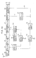
- FIG. 10 shows in block diagram an exemplary one of conventional car-carried FM stereo receivers.
- an FM stereo signal of a high frequency inputted from an antenna 21 is amplified and converted into an intermediate frequency (IF) signal by a front end section 22.
- IF intermediate frequency
- the IF signal is amplified by an IF amplifier 23 having a limiter function and then converted into an FM composite signal by an FM detecting circuit 24.
- the FM composite signal is amplified by an amplifier 25 and then passes through a muting control circuit 26, whereafter it is separated into left (L) and right (R) channel signals by a multiplex (MPX) demodulating circuit 27.
- MPX multiplex
- the left and right channel signals are supplied to a separation control circuit 28 for controlling a degree of separation of left and right channel signals and then pass through a frequency characteristic control circuit 29 for attenuating a high frequency level of left and right channel signals. Then, the left and right channel signals are outputted separately from the frequency characteristic control circuit 29, that is, from the FM stereo receiver.
- a level detecting circuit 31 of AM detection construction such as a so-called S meter detects a signal level of the IF amplifier 23 as a signal level which increases in proportion to a reception electric field strength value.
- the signal level thus detected is supplied to a pair of level setting circuits 32 and 33.
- An output signal of the level setting circuit 32 is inputted to a control signal generating circuit 34, so that a control signal A corresponding to the IF signal level is produced from the control signal generating circuit 34.
- the control signal A causes the muting control circuit 26 to start its variable attenuating operation when the reception input level, that is, the reception electric field strength value, drops below a certain value, but when the reception input level further drops, the control signal A causes the attenuating amount of the muting controlling circuit 26 to be varied continuously in response to the reception input level.
- a frequency displacement detecting circuit 35 instructs, when the input signal level is further dropped by a frequency displacement or the like and the output of the amplifying circuit 25 is dropped accordingly, the control signal generating circuit 34 to reduce the attenuating amount of the muting control circuit 26 infinitely to put the FM stereo receiver into a muted condition.
- An output of the other level setting circuit 33 is inputted to a time constant circuit 36 at which a control signal B having suitably controlled rising and falling edge characteristics is produced.
- the frequency response of the frequency characteristic control circuit 29 is controlled in response to the control signal B.
- control signal B is converted into a suitable level by a level controlling circuit 37 to make a separation degree adjusting signal C for the separation controlling circuit 28.
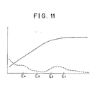
- FIG. 11 there are shown operation characteristics of of the FM stereo receiver.
- a first value E1 for example, 45 dB/ ⁇ V or so
- the separation control circuit 28 first starts its operation in response to a separation degree adjusting signal C generated by the level controlling circuit 37. Consequently, as the reception electric field strength value drops, the degree of stereo separation drops while such drop of the S/N ratio is reduced.
- the separation control circuit 37 starts its operation when the reception electric field strength value is 45 dB/ ⁇ V or so, a monaural operation will be entered from a stereo operation at 25 dB/ ⁇ V or so.
- the frequency characteristic control circuit 29 When the reception electric field strength value drops until the level detection value of the level detecting circuit 31 becomes lower than a second value E2 (for example, 35 dB/ ⁇ V or so) shown, the frequency characteristic control circuit 29 operates in response to a control signal B generated by the time constant circuit 38, and subsequently, the attenuation amount in a high frequency region increases as the reception electric field strength value drops. Consequently, while the high frequency characteristic of left and right channel signals drops as the reception electric field strength value drops, the drop of the S/N ratio is reduced. In case the frequency characteristic control circuit 29 operates when the reception electric field value is 35 dB/ ⁇ V or so, frequency characteristic control for a high frequency region up to 15 dB/ ⁇ V or so is performed.
- a second value E2 for example, 35 dB/ ⁇ V or so
- the muting control circuit 26 operates in response to a control signal A generated by the control signal generating circuit 34, and subsequently, the attenuation amount of left and right channel signals is continuously increased as the reception electric field strength value drops. Consequently, while the output level of left and right channel signals drops as the reception electric field strength value drops, increase of the noise level is reduced.
- E3 for example, 25 dB/ ⁇ V or so
- the control signal generating circuit 34 operates in response to a control signal generated by the frequency displacement detecting circuit 35 so that the attenuation amount of the muting control circuit 26 becomes infinite to put the FM stereo receiver into a muted condition.
- the receiving input level that is, the detection value of the reception electric field strength value
- separation of left and right channel signals is varied continuously
- the frequency characteristic with regard to a reproduction signal is varied continuously
- the detection value becomes lower than the second value E2 and further lower than the third value E3 around a monaural operation mode by separation control the reproduction signal reveal is varied continuously.
- frequency characteristic control circuit 29 and muting control circuit 26 are varied continuously from operation starting points of the individual circuits as the reception input level, that is, the reception electric field strength value, drops in this manner, a substantially constant S/N ratio can be assured and the noise level can be reduced independently of a magnitude of the reception electric field strength value as indicated by a broken line curve in FIG. 11.
- control characteristics of individual control circuits are selectively determined while setting the point of compromise between a noise reducing effect and a reducing effect of an unfamiliar feeling and an erroneous operation uniformly.
- the multipass amount may be great or small with an equal detection value of the reception electric field strength.
- control object amounts such as controlling time constants, controlling operation starting voltages, controlling amounts and so forth of the individual control circuits are set uniformly without taking contents of individual factors defining a receiving input condition into consideration. Consequently, it is not possible to variably set controlling conditions of the individual control circuits individually in accordance with conditions of receiving circumstances, and there is a disadvantage that it is difficult to realize it to make improvement in pulse noise reducing effect and a reducing effect in unfamiliar feeling and erroneous operation in accordance with contents of individual factors defining a receiving input condition.
- fuzzy control In recent year, use of a technique of control called fuzzy control has been gradually increased in the technical field of control.
- degrees at which observed values match a plurality of input conditions including fuzzy expressions are determined individually, and control amounts which are considered the best are inferred taking such matching degrees synthetically.
- any of relationships in magnitude among various factors such as reception electric field strength values, multipass amounts and so forth which define a receiving input condition is not determined objectively nor decisively and is a fuzzy expression. For example, even if it is expressed that a reception electric field strength value is high, a degree at which a certain observed reception electric field strength value matches a condition that "a reception electric field strength value is high" is very fuzzy.
- control object amounts of individual control circuits of an FM receiver are fuzzy controlled to individually cope with observed values of individual factors defining a reception input condition of the receiver to make improvement in pulse noise reducing effect and a reducing effect in unfamiliar feeling and erroneous operation consistent with each other.
- a noise reducing circuit for a receiver which includes at least one of a frequency characteristic control circuit, a separation control circuit and a muting control circuit, which comprises an input vector generating circuit for detecting values of different factors which define a receiving input condition of the receiver and generating an input vector which includes the values as factors thereof, fuzzy inference means for fuzzy inferring, using the input vector from the input vector generating circuit as a prerequisite, in accordance with fuzzy production rules provided by membership functions of the factors of the input vector, and a fuzzy controlling signal generating circuit for generating a fuzzy controlling signal for controlling a control object amount of any one of the separation control circuit, frequency characteristic control circuit and muting control circuit or each of any combination of the circuits in accordance with a result of inference produced by the fuzzy inference means.
- noise reducing circuit With the noise reducing circuit, a control object amount of any of the control circuits of the receiver or each of any combination of such control circuits, values of the control object amounts of the control circuits are controlled individually in accordance with observed values of the factors defining a receiving input condition. Accordingly, improvement in pulse noise reducing effect and a reducing effect in unfamiliar feeling and erroneous operation can be made consistent well in accordance with observed values of a condition of receiving environment.
- the noise reducing circuit is incorporated in a receiver such as an AM receiver.
- the receiver includes a separation control circuit 11 for controlling a degree of separation of left and right channel signals of a stereo signal, a frequency control circuit 12 for controlling a frequency characteristic of an output signal, and a muting control circuit 13 for variably attenuating an output signal to effect muting control.
- the noise reducing circuit is connected to the separation control circuit 11, frequency control circuit 12 and muting control circuit 13 of the receiver and includes an input vector generating circuit 14 for detecting values of individual factors which define a receiving input condition and generating an input vector in accordance with such detected values.
- the noise reducing circuit further includes fuzzy inference means 15 which receives an input vector from the input vector generating circuit 14 and executes, using the input vector as a prerequisite, fuzzy inference in accordance with fuzzy production rules provided in the form of membership functions of different factors of the input vector.
- the noise reducing circuit further includes a fuzzy controlling signal generating circuit 16 which receives a result of inference produced by the fuzzy inference means 15 and generates, in accordance with the thus received inference result, fuzzy controlling signals for controlling control amounts of any of the separation controlling circuit 11, frequency characteristic controlling circuit 12 and muting circuit 13 or each of any combination of the circuits 11, 12 and 13.
- the receiver in which the noise reducing circuit of the present invention is incorporated detects values of several factors such as a reception electric field strength and a multipass amount which define a receiving condition as described hereinabove in connection with the conventional FM receiver.
- the thus detected values are inputted to the input vector generating circuit 14.
- the input vector generating circuit 14 In response to the values thus received, the input vector generating circuit 14 generates an input vector which includes the values as factors thereof and transmits it to the fuzzy inference means 15.
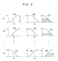
- the fuzzy inference means 15 executes such fuzzy inference processing as illustrated in FIG. 2 in accordance with fuzzy production rules provided in the form of membership functions with regard to individual factors of the input vector to produce a fuzzy controlling signal.
- graphs mA1 to mN1 illustrate membership functions with regard to input vector factors e1 to e n based on a precedent portion of a fuzzy production rule R1, respectively
- graphs mA k to mN k illustrate membership functions with regard to the input vector factors e1 to e n based on a precedent portion of a fuzzy production rule Rk, respectively
- graphs mP1 to mP k illustrate membership functions with regard to results (consequent portions) of the fuzzy production rules R1 to Rk, respectively.
- the individual membership functions are theoretically or experimentally determined in advance for the input vectors e1 to e n and individual fuzzy production rules.
- the fuzzy inference means 15 executes fuzzy inference for the individual input vector factors e1 to e n in accordance with the individual membership functions of the precedents of the corresponding fuzzy production rules R1 to Rk to first determine results of inference with regard to the individual membership functions mP1 to mP k (hatched regions of the individual membership functions mP1 to mP k ). A particular method of determining individual results of inference will be hereinafter described in detail.
- the fuzzy inference means 15 determines a final inference result F using a method of elastic center, a MIN-MAX method or the like in accordance With the results of fuzzy inference.
- the value of the final inference result F decreases as the reception electric field strength value E increases and the multipass amount detection value P decreases, that is, as the receiving condition becomes better, and on the contrary the value of the final inference result F increases as the reception electric field strength value E decreases and the multipass amount detection value P increases, that is, as the receiving condition becomes worse. Details of the method of determining such final inference result F will be hereinafter described.
- the fuzzy controlling signal generating circuit 16 receives such inference result F produced by the fuzzy inference means 15 and generates a fuzzy controlling signal in accordance with the received inference result F to fuzzy control a control object amount of any of the separation control circuit 11, frequency characteristic control circuit 12 and muting circuit 13 or each of a combination of the circuits 11, 12 and 13.
- the control object amount may be a time constant, a controlling operation starting point, a controlling amount or the like of any of the control circuits.
- control object amounts of the control circuits are controlled in accordance with a receiving input condition by fuzzy controlling the separation control circuit 11, frequency characteristic control circuit 12 and muting circuit 13 in this manner, improvement in noise reducing effect and a reducing effect in unfamiliar feeling and erroneous operation can be made consistent with each other well individually in accordance with a receiving condition. Details of such control will be hereinafter described.
- control object amounts of any of the separation control circuit 11, frequency characteristic control circuit 12 and muting circuit 13 or each of a combination of the circuits 11, 12 and 13 are fuzzy controlled as described so far, the control object amounts of the control circuits 11, 12 and 13 are controlled individually in accordance with observed values of factors defining a receiving input condition, and improvement in noise reducing effect and a reducing effect in unfamiliar feeling and erroneous operation can be made consistent with each other well individually in accordance with observed values of conditions of receiving environment.
- control object amount is a controlling time constant of each control circuit.
- the number of factors of an input vector is two including a reception electric field strength value E and a multipass amount detection value P, and the fuzzy production rules are two rules of R11 and R21.
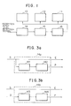
- FIG. 3a and 3b show input vector generating circuits 14a and 14b for generating a reception electric field strength value E and a multipass amount detection value P, respectively, which are factors of an input vector.
- a level detection signal S which may be generated by a level detecting circuit such as the level detecting circuit in the form of an S meter mentioned hereinabove with reference to FIG. 10.
- a multipass amount is included in ac components of the level detection signal S.
- the input vector generating circuit 14a divides the inputted level detection signal S into two portions and outputs one of the two portions as a reception electric field strength value E.
- a level detecting circuit 142 detects a level of the ac components by AM detection and outputs it as a multipass amount detection value P.
- a detection signal D generated by a receiving signal detecting circuit such as the FM detecting circuit 24 described with reference to FIG. 10 is supplied directly or by way of an amplifying circuit such as the amplifying circuit 25 of FIG. 10 to the input vector generating circuit 14b together with the level detection signal S.
- a multipass amount is included in ac components of the detection signal D.
- the input vector generating circuit 14b outputs the inputted level detection signal S as a reception electric field strength value E which is one of factors of an input vector.
- the detection signal D is supplied to a high-pass filter 143 by which ac components thereof are extracted.
- a level detecting circuit 144 detects a level of the ac components by AM detection and outputs it as a multipass amount detection value P which is another factor of the input vector.
- Fuzzy inference processing of the noise reducing circuit of the first embodiment is executed by the fuzzy inference means 15.
- the fuzzy inference processing the following two fuzzy production rules R11 and R21 and membership functions which provide the fuzzy production rules R11 and R21 are set.
- the fuzzy production rules and membership functions are theoretically or experimentally set so that a good receiving condition may be obtained in accordance with a reception electric field strength value E and a multipass amount P.
- Fuzzy inference processing which is executed by the fuzzy inference means 15 will be described in accordance with an inference procedure thereof.
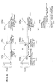
- the controlling signal generating circuit shown includes three comparators 161a to 163a for comparing a controlling time constant value T of a final inference result from the fuzzy inference means 15 with reference voltages Vs1, Vs2 and Vs3, respectively.
- the relationship in magnitude of the reference voltages Vs1, Vs2 and Vs3 is set as Vs1 ⁇ Vs2 ⁇ Vs3.
- the comparators 161a to 163a are connected to the bases of switching transistors 164a, 165a and 166a, respectively, so that each of the switching transistors 164a to 166a is turned on into a conducting state in response to an output generated by a corresponding one of the comparators 161a to 163a.
- Capacitors C1, C2 and C3 are connected at one ends thereof to the collectors of the switching transistors 164a to 166a, respectively, and at the other ends thereof commonly to a resistor R.
- the capacitors C1 to C3 and resistor R constitute a time constant circuit, and a fuzzy controlling signal is outputted from the common connecting point of the capacitors C1 to C3 and resistor R.
- a power source voltage is obtained from a power source battery Vcc connected to the other end of the resistor R.
- the comparators 161a to 163a compare the controlling time constant value T of a final inference result from the fuzzy inference means 15 with the reference voltages Vs1 to Vs3 and each generate an output signal when the controlling time constant value T is higher than the reference voltage Vs1, Vs2 or Vs3, respectively.
- the time constants of the individual control circuits are controlled using the controlling time constant value Tf obtained in such a manner as described above as a fuzzy controlling signal, then since the value of the controlling time constant Tf increases as the reception electric field strength value E increases and the multipass amount detection value P decreases, that is, as the receiving condition becomes better, the individual control circuits do not respond very much to a temporary change of the receiving input condition and maintains the good receiving condition also after then.
- the individual control circuits respond quickly to a change of the receiving input condition and can prevent the receiving condition from getting worse.
- FIGS. 3a, 3b, 6 and 7. A second embodiment of the present embodiment will be described with reference to FIGS. 3a, 3b, 6 and 7.
- the input vector generating circuits shown in FIGS. 3a and 3b are used also as an input vector generating circuit of a noise reducing circuit of the present embodiment.
- control object amount is a controlling operation starting point of each control circuit.
- the number of factors of an input vector is two including a reception electric field strength value E and a multipass amount detection value P similarly as in the case of the first embodiment, and fuzzy production rules are two rules of R12 and R22.
- Fuzzy inference processing executed by the fuzzy inference means 15 Will be described with reference to FIG. 6.
- fuzzy inference processing in the noise reducing circuit of the second embodiment the following two fuzzy production rules R12 and R22 as well as membership functions which provide the fuzzy production rules R12 and R22 are set. Also here, the fuzzy production rules and membership functions are theoretically or experimentally set so that a good receiving condition may be obtained in accordance with a reception electric field strength value E and a multipass amount detection value P.
- fuzzy inference processing executed by the fuzzy inference means 15 in the case of inference processing in accordance with the fuzzy production rule R12, a smaller one of values of the membership functions mA12 and mB12 corresponding to observed reception electric field strength value E and multipass amount detection value P, that is, the value v12 of the membership function mB12, is adopted by the minimum value method.
- a hatched region shown in the diagram (c) of FIG. 6 is determined as a result of inference in accordance with the fuzzy production rule R12 by the head cutting method of Yager.
- membership functions mP12 and mP22 hatchched regions of a result of inference obtained in accordance with the fuzzy production rules R12 and R22 are overlapped with each other in accordance with the MAX composing method to compose a composite membership function mP2 as shown in a diagram (g) of FIG. 6.
- a coordinate value V on the axis of abscissa of the center of gravity of the composite membership function mP2 is outputted as a final inference result, that is, a controlling operation starting point V.
- the final inference result that is, the controlling operation starting point V
- the multipass amount detection value P decreases, that is, as the receiving condition becomes better
- the reception electric field strength value E decreases and the multipass amount detection value P increases, that is, as the receiving condition becomes worse, the value of the controlling operation starting point V decreases.
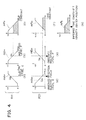
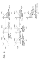
- a controlling signal generating circuit 16 employed in the noise reducing circuit of the second embodiment is shown in FIG. 7.
- the noise reducing circuit shown includes four transistors 161b to 164b, resistors R1 to R3, a reference power source Vs, and constant current sources I1 and I2.
- a differential amplifier is constituted from those circuit elements.
- the noise reducing circuit further includes transistors 165b to 168b and resistors R4 to R7 which constitute an amplifier circuit for an output of the differential amplifier.
- An end of a load resistor RL is connected to a connecting point between the transistors 166b and 168b, and a controlling operation point voltage is outputted from the connecting point.
- the other end of the load resistor RL is connected to a power source Vc.
- Such muting circuit 13, separation control circuit 11 and frequency characteristic control circuit 12 as described hereinabove with reference to FIG. 1 are connected to receive the controlling operation point voltage or fuzzy controlling signal from the controlling signal generating circuit 16.
- the muting control circuit 13 is connected to the controlling signal generating circuit 16 by way of a muting controlling circuit 17 for controlling muting operation which is executed by the muting control circuit 13.
- the separation control circuit 11 is connected to the controlling signal generating circuit 16 by way of a separation controlling circuit 18 for controlling separation control operation which is executed by the separation control circuit 11.
- the frequency characteristic control circuit 12 is connected to the controlling signal generating circuit 16 by way of a frequency characteristic controlling circuit for controlling frequency characteristic controlling operation which is executed by the frequency characteristic control circuit 12.
- a controlling operation starting point V determined by the fuzzy inference means 15 is inputted to the base of the transistor 163b which is one of the differential amplifier mentioned hereinabove.
- a differential output between the controlling operation starting point V and the reference voltage Vs is amplified by the amplifier circuit which is constituted from the transistors 165b to 168b and so forth as described hereinabove, and a controlling operation starting voltage is outputted as a fuzzy controlling signal.
- the fuzzy controlling signal (controlling operation starting voltage V) is supplied to the muting controlling circuit 17, separation controlling circuit 18 and frequency characteristic controlling circuit 19.
- an output of a reception electric field level detecting circuit not shown (which may be the level detecting circuit 31 of FIG. 10) is inputted as a controlling voltage to the muting controlling circuit 17, separation controlling circuit 18 and frequency characteristic controlling circuit 19.
- the muting controlling circuit 17, separation controlling circuit 18 and frequency characteristic controlling circuit 19 start control for the respective control circuits 13, 11 and 12 with a controlling voltage when the controlling voltage level from the level detecting circuit exceeds the fuzzy controlling signal level (controlling operation starting voltage V) received from the controlling signal generating circuit 16.
- a third embodiment of the present embodiment will be described with reference to FIGS. 3, 8 and 9. Also a noise reducing circuit of the present embodiment employs the input vector generating circuit shown in FIG. 3 as an input vector generating circuit.
- the control object amount is either a controlling amount which defines a controlling range of any one of a muting control circuit, a separation control circuit and a frequency characteristic control circuit or a controlling amount for each of any combination of those circuits.
- the number of factors of an input vector is two including a reception electric field strength value E and a multipass amount detection value P similarly as in the case of the first embodiment, and fuzzy production rules are two rules of R13 and R23.
- Fuzzy inference processing executed by the fuzzy inference means 15 in the noise reducing circuit of the present embodiment will be described with reference to FIG. 8.
- fuzzy inference processing the following two fuzzy production rules R13 and R23 as well as membership functions which provide the individual fuzzy production rules R13 and R12 are set. Also here, the fuzzy production rules and membership functions are theoretically or experimentally set so that a good receiving condition may be obtained in accordance with a reception electric field strength value E and a multipass amount detection value P.
- the relationship between the membership functions mA13 and mB13 is such that a smaller one of them, that is, the value v13 of the membership function mB13, is adopted by the minimum value method.
- a hatched region shown in the diagram (c) of FIG. 8 is determined as a result of inference in accordance with the fuzzy production rule R13 by the head cutting method of Yager.
- the relationship between the membership functions mA23 and mB23 is such that a smaller one of them, that is, the value u23 of the membership function mA23, is adopted by the minimum value method.
- a hatched region shown in the diagram (f) of FIG. 8 is obtained by the head cutting method of Yager.
- a coordinate value G on the axis of abscissa of the center of gravity of the composite membership function mP3 is outputted as a final inference result, that is, a controlling amount G.
- the final inference result that is, the value of the controlling amount G
- the multipass amount detection value P decreases, that is, as the receiving condition becomes better
- the reception electric field strength value E decreases and the multipass amount detection value P increases, that is, as the receiving condition becomes worse, the value of the controlling amount G increases.
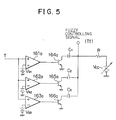
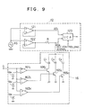
- a fuzzy controlling signal generating circuit 16 which is employed in the noise reducing circuit of the third embodiment is shown in FIG. 9 in which a frequency characteristic control circuit 12 for a channel of demodulated audio signals is also shown. It is to be noted that a control amount of the frequency characteristic control circuit 12 is controlled by a fuzzy controlling signal generated by the fuzzy controlling sing generating circuit 16.
- the fuzzy controlling signal generating circuit 16 includes three comparators 161c, 162c and 163c for comparing an inputted controlling amount G with reference voltages Vs1, Vs2 and Vs3, respectively.
- the relationship in magnitude of the reference voltages Vs1 to Vs3 is set as Vs1 ⁇ Vs2 ⁇ Vs3.
- Switching transistors 164c, 165c and 166c are connected to the comparators 161c to 163c such that they are each turned on into a conducting state when a corresponding one of the comparators 161c to 163c generates an output.
- Capacitors C1, C2 and C3 for the adjustment of controlling ranges are connected at one ends thereof connected to the collectors of the switching transistors 164c to 166c, respectively, while the other ends thereof are connected commonly to a resistor R for the adjustment of a controlling range included in the frequency characteristic control circuit 12.
- the relationship in magnitude of the capacitors C1 to C3 is set as C1 ⁇ C2 ⁇ C3.
- Time constants for the adjustment of controlling ranges are individually set by the resistor R and capacitors C1 to C3.
- the frequency characteristic control circuit 12 further includes a pair of buffers 121 and 122 for an inputted audio signal AS.
- An output of the buffer 121 that is, an audio signal AS1
- VCA variable controlling amplifier
- an output of the other buffer 122 that is another audio signal AS2
- an HCC controlling signal for the adjustment of a high frequency region characteristic is inputted to the variable controlling amplifier 123 from a reception input level detecting circuit not shown which may be, for example, the level setting circuit 33 and the time constant circuit 36 of FIG. 10. Consequently, a mixing amount of audio signals AS from the buffer 121 and resistor R is controlled so that frequency characteristic control of an addition signal is executed.
- the value of the controlling amount G decreases as the observed reception electric field value E increases and the multipass amount detection value P decreases, that is, as the receiving condition becomes better, but on the contrary, as the reception electric field strength value E decreases and the multipass amount detection value P increases, that is, as the receiving condition becomes worse, the value of the controlling amount G increases.
- the comparators 161c, 162c and 163c successively generate an output so that the switching transistors 164c, 165c and 166c are successively put into a conducting state and the time constant for the adjustment of a controlling range increases from RC1 to R(C1 + C2) and further to R(C1 + C2 + C3).
- the high frequency region characteristic of the audio signal AS2 inputted from the buffer 122 to the variable controlling amplifier 123 by way of the resistor R drops as the receiving condition becomes worse and the level of the controlling amount G increases, and the amount of such drop increases in proportion to the level of the controlling amount G.
- frequency characteristic control is executed by controlling the mixing amount of the audio signals AS1 and AS2 from the buffer 21 and resistor R.
- the mixing amount of the audio signal AS2 with the audio signal AS1 decreases, and an audio signal wherein no drop is involved in high frequency characteristic is outputted.
- the HCC controlling signal level becomes lower (the receiving condition becomes worse)
- the mixing amount of the audio signal AS2 with the audio signal AS1 increases, and when it is at the greatest, an audio signal wherein the high frequency characteristic drops to the characteristic of the audio signal AS2 is outputted.
- the controlling range of the high frequency characteristic in this instance is determined by a time constant of a fuzzy controlling signal, that is, a level of a controlling amount G and increases in proportion to the level of the controlling amount G. Accordingly, the frequency characteristic control range increases in proportion to the level of the controlling amount G.
- the fuzzy controlling signal level or controlling amount G decreases and also the controlling amount of the frequency characteristic control circuit 12 decreases as the reception electric field strength value E increases and the multipass amount detection value P decreases, that is, as the receiving condition becomes better, the frequency characteristic of a demodulated audio signal does not drop and a good receiving condition can be maintained.
- the good receiving condition can be maintained if the frequency characteristic control range of the frequency characteristic control circuit 12 is small.
- the controlling amount G increases and the frequency characteristic control range of the frequency characteristic control circuit 12 increases as the reception electric field strength value E decreases and the multipass amount detection value P increases, that is, as the receiving condition becomes worse, even when the receiving input condition is such that noises are included and the S/N ratio is low, the noises are reduced and the S/N ratio is improved so that a good receiving condition can be assured and an erroneous operation can be prevented.
- fuzzy controlling operation of the frequency characteristic control circuit similarly applies to fuzzy controlling operation of the other separation control circuit and muting control circuit.
- an input vector may include a plurality of factors other than those two described above which include a reception electric field strength and a multipass amount.
- characteristics of individual fuzzy production rules and individual membership functions which provide those production rules are not limited to those of the characteristics of the individual embodiments.
- the technique of obtaining a final result of inference that is, an operation sensitivity point SE in accordance with results of inference based on individual membership functions which provide precedent portions of the individual fuzzy production rules may be any one of various known techniques such as a MAX-MIN method other than the method of elastic center which has been made clear with the embodiments.
Landscapes
- Noise Elimination (AREA)
Applications Claiming Priority (2)
| Application Number | Priority Date | Filing Date | Title |
|---|---|---|---|
| JP2056597A JPH03259622A (ja) | 1990-03-09 | 1990-03-09 | ノイズ低減回路 |
| JP56597/90 | 1990-03-09 |
Publications (2)
| Publication Number | Publication Date |
|---|---|
| EP0446470A2 true EP0446470A2 (de) | 1991-09-18 |
| EP0446470A3 EP0446470A3 (en) | 1991-12-11 |
Family
ID=13031617
Family Applications (1)
| Application Number | Title | Priority Date | Filing Date |
|---|---|---|---|
| EP19900124726 Withdrawn EP0446470A3 (en) | 1990-03-09 | 1990-12-19 | Noise reducing circuit |
Country Status (3)
| Country | Link |
|---|---|
| US (1) | US5263184A (de) |
| EP (1) | EP0446470A3 (de) |
| JP (1) | JPH03259622A (de) |
Families Citing this family (9)
| Publication number | Priority date | Publication date | Assignee | Title |
|---|---|---|---|---|
| US5390342A (en) * | 1990-03-14 | 1995-02-14 | Pioneer Electronic Corporation | Receiver using selective diversity receiving system |
| DE4309518A1 (de) * | 1993-03-24 | 1994-10-06 | Blaupunkt Werke Gmbh | Schaltungsanordnung zur Ableitung mindestens eines von der Qualität eines empfangenen Signals abhängigen Qualitätssignals |
| US5371695A (en) * | 1993-10-14 | 1994-12-06 | Ford Motor Company | Method for automatically controlling the bandwidth of a digital filter and adaptive filter utilizing same |
| US5583891A (en) * | 1994-10-31 | 1996-12-10 | Motorola, Inc. | Noise attenuation circuit for amplitude modulated radio and method therefor |
| US5671286A (en) * | 1995-06-09 | 1997-09-23 | Ford Motor Company | Strategy for controlling FM stereo separation and frequency response in noisy reception environments |
| DE19630722C2 (de) * | 1996-07-30 | 1998-06-04 | Aerodata Flugmestechnik Gmbh | Satellitennavigationsempfangsgerät |
| DE69621135D1 (de) * | 1996-12-11 | 2002-06-13 | St Microelectronics Srl | Fuzzy-Logikfilterverfahren und Fuzzy-Logikfilter |
| US6154548A (en) * | 1997-09-27 | 2000-11-28 | Ati Technologies | Audio mute control signal generating circuit |
| JP2004128930A (ja) * | 2002-10-03 | 2004-04-22 | Toyota Industries Corp | Fm受信機、fm受信機のノイズ除去装置及びノイズ除去方法 |
Family Cites Families (9)
| Publication number | Priority date | Publication date | Assignee | Title |
|---|---|---|---|---|
| DE2512412C3 (de) * | 1975-03-21 | 1979-02-01 | Blaupunkt-Werke Gmbh, 3200 Hildesheim | Schaltungsanordnung zum Unterdrücken von Störungen in einem FM-Rundfunkempfänger |
| US3979679A (en) * | 1975-06-30 | 1976-09-07 | California Microwave, Inc. | FM demodulator having squelch circuit using bucket brigade delay line |
| US4416024A (en) * | 1979-12-17 | 1983-11-15 | Sanyo Electric Co., Inc. | Distortion reducing circuit in FM receiver |
| DE3008522A1 (de) * | 1980-03-06 | 1981-09-17 | Basf Ag, 6700 Ludwigshafen | 4-(alpha)-cycloamino-arylmethyl-6-methyl-1,3-dihydro-furo (3,4-c) -pyridin-7-ole, ihre herstellung und verwendung |
| DE3772812D1 (de) * | 1986-04-11 | 1991-10-17 | Mitsubishi Electric Corp | Selbsteinstellender regler. |
| US4833715A (en) * | 1987-03-06 | 1989-05-23 | Alps Electric Co., Ltd. | FM stereo receiver |
| DE3721918C1 (en) * | 1987-07-02 | 1988-11-24 | Becker Autoradio | Method for evaluating the suitability for reception of the frequency-modulated broadcast transmissions received in an FM broadcast receiver, and circuit arrangement for carrying out the method |
| JPH01255331A (ja) * | 1988-04-04 | 1989-10-12 | Alpine Electron Inc | Fmステレオ受信機 |
| JP2696972B2 (ja) * | 1988-08-18 | 1998-01-14 | オムロン株式会社 | フアジイ・ルール発生装置および方法,ならびに確認装置および方法 |
-
1990
- 1990-03-09 JP JP2056597A patent/JPH03259622A/ja active Pending
- 1990-12-19 US US07/629,963 patent/US5263184A/en not_active Expired - Lifetime
- 1990-12-19 EP EP19900124726 patent/EP0446470A3/en not_active Withdrawn
Also Published As
| Publication number | Publication date |
|---|---|
| JPH03259622A (ja) | 1991-11-19 |
| US5263184A (en) | 1993-11-16 |
| EP0446470A3 (en) | 1991-12-11 |
Similar Documents
| Publication | Publication Date | Title |
|---|---|---|
| AU596981B2 (en) | Diversity reception radio receiver | |
| US4742563A (en) | System and method for diversity reception of signals | |
| EP0446470A2 (de) | Schaltung zur Geräuschunterdrückung | |
| EP0018608B1 (de) | Störunterdrückungsschaltung | |
| US20090036085A1 (en) | FM tuner | |
| KR100842155B1 (ko) | 노이즈 캔슬러 및 그것을 이용한 am 수신 장치 | |
| US4063039A (en) | Stereo noise reduction circuit | |
| EP0399557B1 (de) | FM-Stereoempfänger | |
| JPH0683111B2 (ja) | ▲√f▼自動利得制御増幅器 | |
| US4691357A (en) | Stereophonic receiving circuit providing improved switching characteristics between stereophonic and monaural modes | |
| JPH03259624A (ja) | ノイズ低減回路 | |
| JPH01255331A (ja) | Fmステレオ受信機 | |
| JPH0669150B2 (ja) | Fm受信機 | |
| JPH0733471Y2 (ja) | ダイバーシチ受信機 | |
| JPS6255741B2 (de) | ||
| JPH0354923A (ja) | Fmステレオ受信機 | |
| US4633497A (en) | Separation control circuit | |
| US7486796B2 (en) | Stereo receiver for controlling continuously degree of separation | |
| JP3436214B2 (ja) | データ検出方式およびこれを用いた電子機器 | |
| JP3157281B2 (ja) | 受信機 | |
| JPS6366087B2 (de) | ||
| JPH0419864Y2 (de) | ||
| JPS60176314A (ja) | 自動利得調整回路 | |
| JPH036128A (ja) | Fmステレオ受信機 | |
| WO2004062142A1 (en) | Method and circuit arrangement for determining the signal strength in receivers with complex signal processing |
Legal Events
| Date | Code | Title | Description |
|---|---|---|---|
| PUAI | Public reference made under article 153(3) epc to a published international application that has entered the european phase |
Free format text: ORIGINAL CODE: 0009012 |
|
| AK | Designated contracting states |
Kind code of ref document: A2 Designated state(s): DE FR GB |
|
| PUAL | Search report despatched |
Free format text: ORIGINAL CODE: 0009013 |
|
| AK | Designated contracting states |
Kind code of ref document: A3 Designated state(s): DE FR GB |
|
| 17P | Request for examination filed |
Effective date: 19920311 |
|
| 17Q | First examination report despatched |
Effective date: 19940421 |
|
| STAA | Information on the status of an ep patent application or granted ep patent |
Free format text: STATUS: THE APPLICATION IS DEEMED TO BE WITHDRAWN |
|
| 18D | Application deemed to be withdrawn |
Effective date: 19941103 |