EP0444012A2 - Gehäuse für eine Filmkamera - Google Patents
Gehäuse für eine Filmkamera Download PDFInfo
- Publication number
- EP0444012A2 EP0444012A2 EP91890027A EP91890027A EP0444012A2 EP 0444012 A2 EP0444012 A2 EP 0444012A2 EP 91890027 A EP91890027 A EP 91890027A EP 91890027 A EP91890027 A EP 91890027A EP 0444012 A2 EP0444012 A2 EP 0444012A2
- Authority
- EP
- European Patent Office
- Prior art keywords
- housing
- film
- opening
- receiving
- film magazine
- Prior art date
- Legal status (The legal status is an assumption and is not a legal conclusion. Google has not performed a legal analysis and makes no representation as to the accuracy of the status listed.)
- Granted
Links
Images


Classifications
-
- G—PHYSICS
- G03—PHOTOGRAPHY; CINEMATOGRAPHY; ANALOGOUS TECHNIQUES USING WAVES OTHER THAN OPTICAL WAVES; ELECTROGRAPHY; HOLOGRAPHY
- G03B—APPARATUS OR ARRANGEMENTS FOR TAKING PHOTOGRAPHS OR FOR PROJECTING OR VIEWING THEM; APPARATUS OR ARRANGEMENTS EMPLOYING ANALOGOUS TECHNIQUES USING WAVES OTHER THAN OPTICAL WAVES; ACCESSORIES THEREFOR
- G03B19/00—Cameras
- G03B19/18—Motion-picture cameras
Definitions
- the invention relates to a housing for a film camera with clip-on film magazine, which has at least one opening for the passage of the film and a plug-in holder for receiving approaches of the film magazine which are essentially of opposite shape and a locking device for the latter.
- Such a housing was e.g. known from US-OS 4 082 436.
- two openings are provided for the passage of the film, one of which is arranged on the rear wall of the housing and the other on the upper side thereof.
- plug-in brackets are arranged, which are used to selectively hold a film magazine.
- the aim of the invention is to avoid these disadvantages and to propose a housing of the type mentioned at the outset which is distinguished by a simple structure.
- the housing has only one opening for the passage of the film and two different receiving parts are provided, which can optionally be fastened to cover part of the opening for the passage of the film on the outside of the housing and which have a clamping device for fixing of the film magazine are provided.
- the internals of the housing can be of any design and are not in themselves the subject of the invention.
- the internals of the housing can be designed in accordance with US Pat. Nos. 4,536,066, 4,402,581, 4,320,942 and 4,218,116.
- a screw which can be inserted into a threaded bore of the housing is provided for fixing the receiving parts.
- a very secure anchoring of the plug-on part is thus achieved, and it is also possible to introduce forces into the housing via this connection.
- one of the receiving parts is essentially designed as an angle piece, the legs of which enclose an angle which corresponds to that between the rear wall of the housing and the top thereof, one leg having mating surfaces which mate with mating surfaces of the Interact housing and the leg of the receiving part can be inserted into the opening of the housing and partially covers it.
- a corresponding area of the opening of the housing is kept free, on the one hand, to enable the film to be passed through and, on the other hand, the film magazine is supported on the portion of the receiving part which engages in the opening of the housing.
- the mating surfaces in connection with the fastening screw allow forces to be introduced into the housing.
- one of the receiving parts is essentially T-shaped, the central web of which forms an angle with its crossbeam which corresponds to that between the rear wall of the housing and the top thereof has an insertion holder at its free end, a plug-in holder for receiving the film magazine and a clamping device for the film magazine being arranged on the crossbar, the receiving part having an opening for carrying out the film.
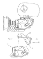
- FIG. 1 shows a housing 1 according to the invention with a film magazine 2 attached to its upper side. The objective that can be inserted into the receptacle 3 is not shown.
- the housing 1 has an opening 6 in the area of the rear wall 4, which also extends into the area of the upper wall 5.
- an insertion holder is arranged in the form of an axis 9 held between two tabs 8, onto which a receiving part 10 with attachments 11 of essentially opposite shape is attached.
- This receiving part 10 is essentially T-shaped, the central web 12 enclosing an angle with the crossbar 13 which corresponds to that between the rear wall 4 and the upper wall 5.
- the middle web 12 covers most of the opening 6.
- a handle 14 is formed on this web 12.
- the crossbar 13 of the receiving part 10 lies with its area facing the lens holder 3 on the upper wall 5 of the housing and is fixed thereon by means of a screw 15.
- an axis 9 ' is held between the integrally formed on the crossbar 13 tabs 8', which serves as an insertion holder for the film magazine 2.
- a clamping hook 16 is pivotally held about an axis held on the crossbar 13, with which the film magazine 2 can be clamped.
- the film magazine 2 is provided with approaches 11 ', which are essentially opposite to the insertion holder of the receiving part 10 are formed. Furthermore, the film magazine 2 is provided with a clamping plate 17, on the upper side of which the clamping hook 16 engages.
- the receiving part 10 In the area of connection of the middle web 12 to the crossbeam 13, the receiving part 10 has an opening 18 which is used to carry out the film 19.
- the receiving part 10 covers the opening 6 of the housing 1 to a large extent.
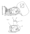
- Fig. 2 shows the receiving part 10 in the raised state from the housing 1. It can also be seen that the receiving part 10 has a support 20 for the film magazine 2, which, as can be seen from FIG. 1, is provided in the usual way with guide rollers for the film 19.
- the leg 13 resting on the upper wall 5 of the housing 1 has vertical or inclined fitting surfaces 25, 26 which cooperate with oppositely designed fitting surfaces of the housing 1, as a result of which the receiving part is supported very securely on the housing 1 results and a safe introduction of forces into the housing is made possible.
- FIG. 3 the same housing 1 as shown in Fig. 1, but with a receiving part 10 'is mounted on the housing 1. As can be seen from FIG. 4, this can be fixed on the housing 1 by means of two screws 15.
- the receiving part 10 has two legs 12', 13 ', which enclose an angle which corresponds to that between the rear wall 4 and the upper wall 5.
- the leg 12 ' engages in the opening 6 of the housing 1 and partially covers it.
- the film magazine 2 is hooked with the approach 11 'in the insertion of the housing 1, which is formed by the axis 9, and fixed by means of the clamping hook 16', which is held on the receiving part 10 '.
- the film 19 is guided over the same rollers of the film guide as in the film magazine 2 arranged on the upper wall 5 of the housing 1.
- a support 20 ' is integrally formed on the receiving part 10'.
Landscapes
- Physics & Mathematics (AREA)
- General Physics & Mathematics (AREA)
- Details Of Cameras Including Film Mechanisms (AREA)
- Camera Bodies And Camera Details Or Accessories (AREA)
- Packages (AREA)
- Materials For Medical Uses (AREA)
Abstract
Description
- Die Erfindung bezieht sich auf ein Gehäuse für eine Filmkamera mit in verschiedenen Lagen aufsteckbarem Filmmagazin, welches mindestens eine Öffnung zur Durchführung des Films und eine Einsteckhalterung zur Aufnahme von im wesentlichen gegengleich geformten Ansätzen des Filmmagazins und eine Verriegelung für dieses aufweist.
- Ein derartiges Gehäuse wurde z.B. durch die US-OS 4 082 436 bekannt. Bei diesem bekannten Gehäuse sind zwei Öffnungen zur Durchführung des Films vorgesehen, von denen eine an der Rückwand des Gehäuses und die andere an der Oberseite desselben angeordnet sind. Im Bereich der beiden Öffnungen sind Einsteckhalterungen angeordnet, die zur wahlweisen Aufnahme eines Filmmagazins dienen.
- Dabei ergibt sich jedoch der Nachteil, daß die jeweils nicht zur Aufnahme des Magazins verwendete Öffnung mit einem Deckel verschlossen werden muß und der Aufwand für Licht-, Schmutz- und Schalldichtheit entsprechend ist.
- Ziel der Erfindung ist es diese Nachteile zu vermeiden und ein Gehäuse der eingangs erwähnten Art vorzuschlagen das sich durch einen enfachen Aufbau auszeichnet.
- Erfindungsgemäß wird dies dadurch erreicht, daß das Gehäuse lediglich eine Öffnung zur Durchführung des Films aufweist und zwei unterschiedliche Aufnahmeteile vorgesehen sind, die wahlweise zur Abdeckung eines Teiles der Öffnung zur Durchführung des Filmes auf der Außenseite des Gehäuses befestigbar sind und die mit einer Klemmeinrichtung zur Fixierung des Filmmagazins versehen sind.
- Auf diese Weise ergibt sich ein sehr einfacher Aufbau, wobei ein Wechsel des Aufsteckortes des Filmmagazins an dem Gehäuse sehr einfach möglich ist.
- Die Einbauten des Gehäuses können beliebig ausgebildet sein und sind an sich nicht Gegenstand der Erfindung. So können die Einbauten des Gehäuses z.B. gemäß den US-PSen 4 536 066, 4 402 581, 4 320 942 und 4 218 116 ausgebildet sein.
- Dabei kann weiters vorgesehen sein, daß zur Fixierung der Aufnahmeteile eine in eine Gewindebohrung des Gehäuses einsetzbare Schraube vorgesehen ist.
- Damit wird eine sehr sichere Verankerung des Aufsteckteiles errreicht, wobei auch eine Einleitung von Kräften über diese Verbindung in das Gehäuse möglich ist.
- Nach einem weiteren Merkmal der Erfindung kann vorgesehen sein, daß einer der Aufnahmeteile im wesentlichen als Winkelstück ausgebildet ist, dessen Schenkel einen Winkel einschließen, der jenem zwischen der Rückwand des Gehäuses und dessen Oberseite entspricht, wobei der eine Schenkel Paßflächen aufweist, die mit Paßflächen des Gehäuses zusammenwirken und der Schenkel des Aufnahmeteiles in die Öffnung des Gehäuses einsetzbar ist und diese teilweise überdeckt.
- Dadurch wird einerseits ein entsprechender Bereich der Öffnung des Gehäuses freigehalten, um eine Durchführung des Films zu ermöglichen und anderseits eine Abstützung des Filmmagazins eben an dem in der Öffnung des Gehäuses eingreifenden Abschnittes des Aufnahmeteiles sichergestellt ist. Dabei wird durch die Paßflächen in Verbindung mit der Befestigungsschraube eine Einleitung von Kräften in das Gehäuse möglich.
- Nach einem weiteren Merkmal der Erfindung ist vorgesehen, daß einer der Aufnahmeteile im wesentlichen T-förmig ausgebildet ist, dessen mittlerer Steg mit seinem Querbalken einen Winkel einschließt, der jenem zwischen der Rückwand des Gehäuses und dessen Oberseite entspricht an seinem freien Ende eine Einsteckhalterung aufweist, wobei an dem Querbalken eine zur Aufnahme des Filmmagazins dienende Einsteckhalterung und eine Klemmeinrichtung für das Filmmagazin angeordnet sind, wobei der Aufnahmeteil einen Durchbruch zur Durchführung des Films aufweist.
- Mit einem solchen Aufnahmeteil ist einerseits eine sichere Befestigung des Magazins sichergestellt, wobei ein solcher Aufnahmeteil die Einleitung der Kräfte in das Gehäuse ermöglicht.
- Die Erfindung wird nun anhand der Zeichnung näher erläutert. Dabei zeigen:
- Fig. 1 einen Schnitt durch ein Gehäuse mit an dessen Oberseite aufgestecktem Filmmagazin,
- Fig. 2 eine Explosionsdarstellung eines Gehäuses mit einem Aufnahmeteil nach Fig. 1,
- Fig. 3 einen Schnitt durch ein Gehäuse mit an dessen Rückseite aufgestecktem Filmmagazin und
- Fig. 4 eine Explosionsdarstellung eines Gehäuses mit einem Aufnahmeteil nach Fig. 3.
- Fig. 1 zeigt ein erfindungsgemäßes Gehäuse 1 mit einem an dessen Oberseite aufgestecktem Filmmagazin 2. Dabei ist das Objektiv, das in die Aufnahme 3 einsetzbar ist, nicht dargestellt.
- Das Gehäuse 1 weist im Bereich der Rückwand 4 eine Öffnung 6, die sich auch in den Bereich der oberen Wand 5 hineinerstreckt.
- Im Inneren des Gehäuses sind die üblichen Einbauten, wie Filmführung 7 samt Antrieb, Greiferwerk u.s.w. untergebracht, die in üblicher Weise, z.B. gemäß den US-PSen 4 536 066, 4 402 581, 4 320 942 und 4 218 116 ausgebildet sein können und an sich nicht Bestandteil der Erfindung sind.
- Im unteren Bereich der Rückwand 4 des Gehäuses 1 ist eine Einsteckhalterung in Form einer zwischen zwei Laschen 8 gehaltenen Achse 9 angeordnet, auf die ein Aufnahmeteil 10 mit im wesentlichen gegengleich geformten Ansätzen 11 aufgesteckt ist.
- Dieser Aufnahmeteil 10 ist im wesentlichen T-förmig ausgebildet, wobei der mittlere Steg 12 mit dem Querbalken 13 einen Winkel einschließt, der jenem zwischen der Rückwand 4 und der oberen Wand 5 entspricht. Dabei überdeckt der mittlere Steg 12 den größten Teil der Öffnung 6. An diesem Steg 12 ist weiters eine Handhabe 14 angeformt.
- Der Quersteg 13 des Aufnahmeteiles 10 liegt mit seinem der Objektivaufnahme 3 zugekehrten Bereich auf der oberen Wand 5 des Gehäuses auf und ist an dieser mittels einer Schraube 15 fixiert.
- An dem einen Ende des Querbalkens 13 ist eine Achse 9′ zwischen an dem Quersteg 13 angeformten Laschen 8′ gehalten, die als Einsteckhalterung für das Filmmagazin 2 dient. Am zweiten Endes des Querbalkens 13 ist ein Klemmhaken 16 um eine an dem Querbalken 13 gehaltenen Achse schwenkbar gehalten, mit dem das Filmmagazin 2 festklemmbar ist.
- Das Filmmagazin 2 ist mit Ansätzen 11′ versehen, die im wesentlichen gegengleich zur Einsteckhalterung des Aufnahmeteiles 10 ausgebildet sind. Weiters ist das Filmmagazin 2 mit einer Klemmplatte 17 versehen, an dessen Oberseite der Klemmhaken 16 angreift.
- Im Verbindungsbereich des mittleren Steges 12 mit dem Querbalken 13 weist der Aufnahmeteil 10 einen Durchbruch 18 auf, der zur Durchführung des Films 19 dient.
- Der Aufnahmeteil 10 deckt die Öffnung 6 des Gehäuses 1 zu einem großen Teil ab.
- Fig. 2 zeigt den Aufnahmeteil 10 im vom Gehäuse 1 abgehobenen Zustand. Dabei ist auch zu ersehen, daß der Aufnahmeteil 10 eine Abstützung 20 für das Filmmagazin 2, das wie aus der Fig. 1 zu ersehen ist, in üblicher Weise mit Führungsrollen für den Film 19 versehen ist, aufweist.
- Beim Aufnahmeteil 10 weist der an der oberen Wand 5 des Gehäuses 1 aufliegenden Schenkel 13 senkrecht, bzw. schräg verlaufende Paßflächen 25, 26 auf, die mit gegengleich ausgebildeten Paßflächen des Gehäuses 1 zusammenwirken, wodurch sich eine sehr sichere Abstützung des Aufnahmeteiles an dem Gehäuse 1 ergibt und eine sichere Einleitung von Kräften in das Gehäuse ermöglicht wird.
- In Fig. 3 ist das gleiche Gehäuse 1 wie in der Fig. 1 dargestellt, wobei jedoch ein Aufnahmeteil 10′ an dem Gehäuse 1 montiert ist. Dieses ist, wie aus der Fig. 4 zu ersehen ist, mittels zweier Schrauben 15 an dem Gehäuse 1 festlegbar.
- Der Aufnahmeteil 10′ weist zwei Schenkel 12′, 13′ auf, die einen Winkel einschließen, der jenem zwischen der Rückwand 4 und der oberen Wand 5 entspricht. Dabei greift der Schenkel 12′ in die Öffnung 6 des Gehäuses 1 ein und deckt diese teilweise ab.
- Das Filmmagazin 2 ist dabei mit dem Ansatz 11′ in der Einsteckhalterung des Gehäuses 1, die durch die Achse 9 gebildet ist, eingehakt und mittels des Klemmhakens 16′, der an dem Aufnahmeteil 10′ gehalten ist, fixiert.
- Der Film 19 ist dabei über die gleichen Rollen der Filmführung geführt, wie bei dem an der oberen Wand 5 des Gehäuses 1 angeordneten Filmmagazin 2.
- Wie aus der Fig. 4 zu ersehen ist, ist auch an dem Aufnahmeteil 10′ eine Stütze 20′ angeformt.
Claims (4)
- Gehäuse für eine Filmkamera mit in verschiedenen Lagen aufsteckbarem Filmmagazin, welches mindestens eine Öffnung zur Durchführung des Films und eine Einsteckhalterung zur Aufnahme von im wesentlichen gegengleich geformten Ansätzen des Filmmagazins und eine Verriegelung für dieses aufweist, dadurch gekennzeichnet, daß das Gehäuse (1) lediglich eine Öffnung (6) zur Durchführung des Films (19) aufweist und zwei unterschiedliche Aufnahmeteile (10, 10′) vorgesehen sind, die wahlweise zur Abdeckung eines Teiles der Öffnung (6) zur Durchführung des Filmes (19) auf der Außenseite des Gehäuses (1) befestigbar sind und die mit einer Klemmeinrichtung zur Fixierung des Filmmagazins (2) versehen sind.
- Gehäuse nach Anspruch 1, dadurch gekennzeichnet, daß zur Fixierung der Aufnahmeteile (10, 10′) eine in eine Gewindebohrung des Gehäuses (1) einsetzbare Schraube (15) vorgesehen ist.
- Gehäuse nach Anspruch 1 oder 2, dadurch gekennzeichnet, daß einer der Aufnahmeteile (10′) im wesentlichen als Winkelstück ausgebildet ist, dessen Schenkel (12′, 13′) einen Winkel einschließen, der jenem zwischen der Rückwand (4) des Gehäuses (1) und dessen obere Wand (5) entspricht, wobei der eine Schenkel (13′) Paßflächen (25, 26) aufweist, die mit Paßflächen des Gehäuses (1) zusammenwirken und der Schenkel (12′) des Aufnahmeteiles (10′) in die Öffnung (6) des Gehäuses einsetzbar ist und dieseteilweise überdeckt.
- Gehäuse nach einem der Ansprüche 1 bis 3, dadurch gekennzeichnet, daß einer der Aufnahmeteile (10) im wesentlichen T-förmig ausgebildet ist, dessen mittlerer Steg (12) mit seinem Querbalken (13) einen Winkel einschließt, der jenem zwischen der Rückwand des Gehäuses (1) und dessen oberer Wand (5) entspricht an seinem freien Ende eine Einsteckhalterung aufweist, wobei an dem Querbalken (13) eine zur Aufnahme des Filmmagazins (2) dienende Einsteckhalterung und eine Klemmeinrichtung für das Filmmagazin (2) angeordnet sind, wobei der Aufnahmeteil einen Durchbruch (18) zur Durchführung des Films (19) aufweist.
Applications Claiming Priority (2)
| Application Number | Priority Date | Filing Date | Title |
|---|---|---|---|
| AT386/90 | 1990-02-20 | ||
| AT0038690A AT394458B (de) | 1990-02-20 | 1990-02-20 | Gehaeuse fuer eine filmkamera |
Publications (3)
| Publication Number | Publication Date |
|---|---|
| EP0444012A2 true EP0444012A2 (de) | 1991-08-28 |
| EP0444012A3 EP0444012A3 (en) | 1992-07-08 |
| EP0444012B1 EP0444012B1 (de) | 1995-11-02 |
Family
ID=3489219
Family Applications (1)
| Application Number | Title | Priority Date | Filing Date |
|---|---|---|---|
| EP91890027A Expired - Lifetime EP0444012B1 (de) | 1990-02-20 | 1991-02-18 | Gehäuse für eine Filmkamera |
Country Status (4)
| Country | Link |
|---|---|
| US (1) | US5100228A (de) |
| EP (1) | EP0444012B1 (de) |
| AT (2) | AT394458B (de) |
| DE (1) | DE59106786D1 (de) |
Families Citing this family (1)
| Publication number | Priority date | Publication date | Assignee | Title |
|---|---|---|---|---|
| AT407092B (de) * | 1998-02-18 | 2000-12-27 | Bauer Fritz | Kamerasystem |
Family Cites Families (12)
| Publication number | Priority date | Publication date | Assignee | Title |
|---|---|---|---|---|
| FR387096A (fr) * | 1908-02-01 | 1908-06-30 | Pablo Audouard | Appareil cinématographique et photographique |
| US1512477A (en) * | 1921-08-01 | 1924-10-21 | Erik W Nelson | Motion-picture camera |
| US2597176A (en) * | 1949-12-22 | 1952-05-20 | Rca Corp | Film supply and take-up apparatus |
| US2752107A (en) * | 1952-08-16 | 1956-06-26 | Jr Harry R Schenck | Film magazine |
| GB890902A (en) * | 1959-09-17 | 1962-03-07 | Lowell Alexander Wilkins | Improvements in or relating to motion picture cameras |
| FR2121196A5 (de) * | 1971-01-08 | 1972-08-18 | Gaf Corp | |
| US3782812A (en) * | 1973-02-22 | 1974-01-01 | Eastman Kodak Co | Cartridge positioning apparatus |
| USRE32138E (en) * | 1973-08-15 | 1986-05-06 | Panavision, Incorporated | Motion picture camera |
| US4082436A (en) * | 1975-06-02 | 1978-04-04 | Gottschalk Robert E | Motion picture camera |
| JPS54115129A (en) * | 1978-02-28 | 1979-09-07 | Asahi Optical Co Ltd | Camera capable of using both brony film and 70 mm film |
| US4298255A (en) * | 1980-07-14 | 1981-11-03 | Panavision, Incorporated | Apparatus for preflashing motion picture film |
| US4630907A (en) * | 1986-01-08 | 1986-12-23 | Panavision, Inc. | Apparatus for pivotally mounting a film magazine to a motion picture camera |
-
1990
- 1990-02-20 AT AT0038690A patent/AT394458B/de not_active IP Right Cessation
-
1991
- 1991-02-18 EP EP91890027A patent/EP0444012B1/de not_active Expired - Lifetime
- 1991-02-18 AT AT91890027T patent/ATE129818T1/de not_active IP Right Cessation
- 1991-02-18 DE DE59106786T patent/DE59106786D1/de not_active Expired - Lifetime
- 1991-02-19 US US07/657,044 patent/US5100228A/en not_active Expired - Lifetime
Also Published As
| Publication number | Publication date |
|---|---|
| EP0444012B1 (de) | 1995-11-02 |
| ATE129818T1 (de) | 1995-11-15 |
| EP0444012A3 (en) | 1992-07-08 |
| DE59106786D1 (de) | 1995-12-07 |
| AT394458B (de) | 1992-04-10 |
| ATA38690A (de) | 1991-09-15 |
| US5100228A (en) | 1992-03-31 |
Similar Documents
| Publication | Publication Date | Title |
|---|---|---|
| AT404664B (de) | Vorrichtung zur befestigung der frontblende einer schublade an schubladenzargen | |
| DE3744941C2 (de) | ||
| AT399261B (de) | Frontblendenhalterung für schubladen | |
| EP0444012A2 (de) | Gehäuse für eine Filmkamera | |
| EP0019243B1 (de) | Stativ für Projektionsleinwände | |
| CH624796A5 (en) | Housing for electrical telecommunications and metrology apparatuses | |
| DE19816835C2 (de) | Computergehäusebausatz | |
| EP0596235A1 (de) | Behälter für Tonträger | |
| DE3002408A1 (de) | Vorrichtung zur sicherung von schubladen in schubladenschraenken | |
| DE3047263A1 (de) | Laengenverstellbarer brillenbuegel | |
| EP0504619A1 (de) | Waschmaschine | |
| DE4200315C1 (en) | Socket holder for frame or switch cabinet - has transverse carrier joining two supports in parallel of U=shaped profile | |
| DE2552649A1 (de) | Diebstahlssicherung fuer ausstellungsstuecke | |
| DE29919473U1 (de) | Griffbügel für ein Gehäuse, insbesondere Kunststoffgehäuse, zur Aufnahme elektronischer und/oder elektrotechnischer Geräte | |
| DE202024103864U1 (de) | Messgerät | |
| DE2821256C2 (de) | Vorrichtung zur Preisauszeichnung in einem Verkaufskühlmöbel | |
| AT394450B (de) | Behaelter fuer ein druckmessgeraet | |
| DE7704219U1 (de) | Haltevorrichtung fuer eine schere | |
| DE2119101C3 (de) | Münzsperrvorrichtung | |
| AT403982B (de) | Rückwand für bilderrahmen | |
| DE9104063U1 (de) | Einrichtung zur lösbaren Verbindung nebeneinanderliegender Gehäuse | |
| EP0273163A1 (de) | Anordnung zur Halterung eines Gehäuses an einem Träger, insbesondere für Kraftfahrzeuge | |
| DE3030161A1 (de) | Leuchtengehaeuse mit mindestens einer hakenfoermigen feder zur loesbaren halterung von einsaetzen | |
| DE9320121U1 (de) | Vorrichtung zur Befestigung einer Tafel an einer Unterlage | |
| DE3334354A1 (de) | Verriegelungsvorrichtung fuer den mitnehmer eines passiven sicherheitsgurtes |
Legal Events
| Date | Code | Title | Description |
|---|---|---|---|
| PUAI | Public reference made under article 153(3) epc to a published international application that has entered the european phase |
Free format text: ORIGINAL CODE: 0009012 |
|
| AK | Designated contracting states |
Kind code of ref document: A2 Designated state(s): AT BE CH DE DK ES FR GB GR IT LI LU NL SE |
|
| PUAL | Search report despatched |
Free format text: ORIGINAL CODE: 0009013 |
|
| AK | Designated contracting states |
Kind code of ref document: A3 Designated state(s): AT BE CH DE DK ES FR GB GR IT LI LU NL SE |
|
| 17P | Request for examination filed |
Effective date: 19921207 |
|
| 17Q | First examination report despatched |
Effective date: 19940803 |
|
| GRAA | (expected) grant |
Free format text: ORIGINAL CODE: 0009210 |
|
| AK | Designated contracting states |
Kind code of ref document: B1 Designated state(s): AT BE CH DE DK ES FR GB GR IT LI LU NL SE |
|
| PG25 | Lapsed in a contracting state [announced via postgrant information from national office to epo] |
Ref country code: ES Free format text: THE PATENT HAS BEEN ANNULLED BY A DECISION OF A NATIONAL AUTHORITY Effective date: 19951102 Ref country code: GR Free format text: LAPSE BECAUSE OF FAILURE TO SUBMIT A TRANSLATION OF THE DESCRIPTION OR TO PAY THE FEE WITHIN THE PRESCRIBED TIME-LIMIT Effective date: 19951102 Ref country code: NL Free format text: LAPSE BECAUSE OF FAILURE TO SUBMIT A TRANSLATION OF THE DESCRIPTION OR TO PAY THE FEE WITHIN THE PRESCRIBED TIME-LIMIT Effective date: 19951102 Ref country code: BE Effective date: 19951102 Ref country code: DK Effective date: 19951102 |
|
| REF | Corresponds to: |
Ref document number: 129818 Country of ref document: AT Date of ref document: 19951115 Kind code of ref document: T |
|
| REF | Corresponds to: |
Ref document number: 59106786 Country of ref document: DE Date of ref document: 19951207 |
|
| ITF | It: translation for a ep patent filed | ||
| PG25 | Lapsed in a contracting state [announced via postgrant information from national office to epo] |
Ref country code: SE Effective date: 19960202 |
|
| PG25 | Lapsed in a contracting state [announced via postgrant information from national office to epo] |
Ref country code: CH Free format text: LAPSE BECAUSE OF NON-PAYMENT OF DUE FEES Effective date: 19960228 Ref country code: LI Free format text: LAPSE BECAUSE OF NON-PAYMENT OF DUE FEES Effective date: 19960228 |
|
| PG25 | Lapsed in a contracting state [announced via postgrant information from national office to epo] |
Ref country code: LU Free format text: LAPSE BECAUSE OF NON-PAYMENT OF DUE FEES Effective date: 19960229 |
|
| ET | Fr: translation filed | ||
| GBT | Gb: translation of ep patent filed (gb section 77(6)(a)/1977) |
Effective date: 19960217 |
|
| NLV1 | Nl: lapsed or annulled due to failure to fulfill the requirements of art. 29p and 29m of the patents act | ||
| PLBE | No opposition filed within time limit |
Free format text: ORIGINAL CODE: 0009261 |
|
| STAA | Information on the status of an ep patent application or granted ep patent |
Free format text: STATUS: NO OPPOSITION FILED WITHIN TIME LIMIT |
|
| REG | Reference to a national code |
Ref country code: CH Ref legal event code: PL |
|
| 26N | No opposition filed | ||
| REG | Reference to a national code |
Ref country code: GB Ref legal event code: IF02 |
|
| PGFP | Annual fee paid to national office [announced via postgrant information from national office to epo] |
Ref country code: FR Payment date: 20100315 Year of fee payment: 20 Ref country code: IT Payment date: 20100226 Year of fee payment: 20 |
|
| PGFP | Annual fee paid to national office [announced via postgrant information from national office to epo] |
Ref country code: GB Payment date: 20100219 Year of fee payment: 20 Ref country code: AT Payment date: 20100228 Year of fee payment: 20 |
|
| PGFP | Annual fee paid to national office [announced via postgrant information from national office to epo] |
Ref country code: DE Payment date: 20100423 Year of fee payment: 20 |
|
| REG | Reference to a national code |
Ref country code: DE Ref legal event code: R071 Ref document number: 59106786 Country of ref document: DE |
|
| REG | Reference to a national code |
Ref country code: GB Ref legal event code: PE20 Expiry date: 20110217 |
|
| PG25 | Lapsed in a contracting state [announced via postgrant information from national office to epo] |
Ref country code: GB Free format text: LAPSE BECAUSE OF EXPIRATION OF PROTECTION Effective date: 20110217 |
|
| PG25 | Lapsed in a contracting state [announced via postgrant information from national office to epo] |
Ref country code: DE Free format text: LAPSE BECAUSE OF EXPIRATION OF PROTECTION Effective date: 20110218 |