EP0443774A1 - Electrical connector and terminal therefore - Google Patents
Electrical connector and terminal therefore Download PDFInfo
- Publication number
- EP0443774A1 EP0443774A1 EP91301193A EP91301193A EP0443774A1 EP 0443774 A1 EP0443774 A1 EP 0443774A1 EP 91301193 A EP91301193 A EP 91301193A EP 91301193 A EP91301193 A EP 91301193A EP 0443774 A1 EP0443774 A1 EP 0443774A1
- Authority
- EP
- European Patent Office
- Prior art keywords
- pair
- terminal
- base
- support sections
- opposing support
- Prior art date
- Legal status (The legal status is an assumption and is not a legal conclusion. Google has not performed a legal analysis and makes no representation as to the accuracy of the status listed.)
- Withdrawn
Links
Images

Classifications
-
- H—ELECTRICITY
- H01—ELECTRIC ELEMENTS
- H01R—ELECTRICALLY-CONDUCTIVE CONNECTIONS; STRUCTURAL ASSOCIATIONS OF A PLURALITY OF MUTUALLY-INSULATED ELECTRICAL CONNECTING ELEMENTS; COUPLING DEVICES; CURRENT COLLECTORS
- H01R13/00—Details of coupling devices of the kinds covered by groups H01R12/70 or H01R24/00 - H01R33/00
- H01R13/40—Securing contact members in or to a base or case; Insulating of contact members
- H01R13/42—Securing in a demountable manner
- H01R13/428—Securing in a demountable manner by resilient locking means on the contact members; by locking means on resilient contact members
- H01R13/432—Securing in a demountable manner by resilient locking means on the contact members; by locking means on resilient contact members by stamped-out resilient tongue snapping behind shoulder in base or case
-
- H—ELECTRICITY
- H01—ELECTRIC ELEMENTS
- H01R—ELECTRICALLY-CONDUCTIVE CONNECTIONS; STRUCTURAL ASSOCIATIONS OF A PLURALITY OF MUTUALLY-INSULATED ELECTRICAL CONNECTING ELEMENTS; COUPLING DEVICES; CURRENT COLLECTORS
- H01R13/00—Details of coupling devices of the kinds covered by groups H01R12/70 or H01R24/00 - H01R33/00
- H01R13/02—Contact members
- H01R13/10—Sockets for co-operation with pins or blades
- H01R13/11—Resilient sockets
- H01R13/115—U-shaped sockets having inwardly bent legs, e.g. spade type
Definitions
- This invention generally relates to electrical connectors and, more particularly, to an electrical connector including a solderless terminal.
- Such a connector includes a housing having cavities for receiving terminals terminated to insulated conductors.
- the terminal has a female contact portion at one end which is inserted into a respective cavity, with a trailing or opposite end terminated to the conductor.
- a male pin is inserted into the female contact portion, an electrical connection is made with the pin.
- the housing usually is molded of plastic material and the terminal cavities in the housing are formed by die core inserts which are retracted after the molding operation. In order to afford retractions of the core inserts, interior areas of the cavities are of lesser dimensions than outer areas of the cavities.
- the terminals often are fabricated from sheet metal material which is stamped and formed to the shape of the desired terminal.
- the terminal must have female receptacle means at one end and conductor terminal means at the other end.
- Support sections usually are provided to support the terminal in its respective cavity against twisting or other undesirable movement relative to the housing.
- the terminal has longitudinal rigidifying means and latch means in addition to the other stated portions or sections. Keeping in mind that all of these functional portions of the terminal are provided within an extremely small stamped and formed metal member, it can be understood why it most often is difficult to insert and remove the terminal from its respective molded cavity.
- This invention is directed to providing a new and improved electrical connector of the character described including an improved terminal construction providing self-contained rigidity as well as improved support within a connector housing cavity.
- An object, therefore, of the invention is to provide a new and improved electrical connector and terminal construction.
- an electrical connector wherein a housing has an elongated cavity with an inner end and an outer end. The height of the inner end of the cavity is less than an area of the cavity spaced from the inner end in a direction toward the outer end.
- a complementary terminal includes an elongated base having contact receptacle means at one end and conductor terminal means at the other end. The terminal is inserted into the housing cavity with the contact receptacle means leading and the conductor terminal means trailing.
- the terminal has a first pair of opposing support sections extending upwardly from opposite lateral sides at the one end of the elongated base for receiving a mating contact member, such as a pin, inserted into the receptacle means of the terminal.
- a second pair of opposing support sections extend upwardly from the base at a position intermediate the ends of the base. The opposing support sections laterally support the terminal within the housing cavity. The height of the first pair of opposing support sections is less than the height of the second pair of opposing support sections to facilitate insertion and removal of a the terminal in a respective cavity in the housing.
- the receptacle means of the terminal are defined by a pair of resilient contact beams having distal ends pointing in a direction toward the conductor terminal means at the other end of the base.
- the beams are formed integral with the first pair of opposing support sections.
- the base of the terminal is generally flat and includes a reinforcing rib formed integrally with the base and extending lengthwise thereof in the area of the second pair of opposing support sections. The reinforcing rib projects upwardly from the flat base.
- a latch tab is formed out of the base and projects from the underside thereof for latching into a complementary recess in an appropriate connector housing.
- the invention is directed to an electrical connector which includes one or more terminals, generally designated 10, which are inserted into appropriate cavities in a connector housing which will be described in greater detail in relation to Figure 4.
- terminal 10 is fabricated from sheet metal material by an appropriate stamping and forming process.
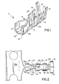
- the terminal includes an elongated, generally flat base 12 having contact receptacle means, generally designated 14, at one end, and conductor terminal means, generally designated 16, at the other end.
- Conductor terminal means 16 is in the form of two opposing pairs of tabs 18 which are provided for crimping over an electrical cable to establish an electrical connection therewith. It can be seen that the slots which separate the two opposing pairs of tabs 18 end at points 20 above flat base 12 to provide rigidity in a vertical direction or in planes generally transverse to the flat base. At this point, it should be understood that notwithstanding the fact that the electrical connector may be used in omni-directional applications, the use of such terms as “upwardly”, “above”, “below” and the like in this specification and the claims hereof are in reference to the orientation of terminal 10 in the drawings, particularly, Figures 1-3.
- Contact receptacle means 14 is formed by a pair of resilient contact beams 22 which form a female receptacle of terminal 10 to receive a male contact, such as a male pin, inserted between beams 22 to establish an electrical connection with the pin. It can be seen that the pair of beams are bent toward each other to provide an inwardly tapering female receptacle.
- a first pair of opposing support sections 24 extend upwardly from opposite lateral sides of base 12 at the receptacle means end thereof for receiving the mating male contact or pin therebetween.
- a second pair of opposing support sections 26 extend upwardly from base 12 at a position intermediate the ends of the base and, more particularly, intermediate receptacle means 14 and conductor terminal means 16.
- Figure 2 shows morae definitively the tapering nature of resilient beams 22 and, in conjunction with Figure 1, it can be seen that the beams are formed integral with the first pair of opposing support sections 24.
- the rear pair of crimping tabs 18 are spread wider apart than the forward pair of tabs 18 so that the rear pair of tabs can be crimped over an insulated portion of the electrical cable, and the forward pair of tabs can be crimped over the exposed conductor of the cable.
- the invention contemplates that the height of the first pair of opposing support sections 24 be less than the height of the second pair of opposing support sections 26. This can be seen clearly in Figure 3.
- This differential in height between the two pairs of opposing support sections facilitate insertion and removal of the terminal in a complementary cavity of an appropriate connector housing because such cavities preferably are molded in one configuration or another to enable removal of the molding core inserts, as described above.
- Figures 2 and 3 also show a latch tab 28 which is stamped out of the terminal sheet metal blank to project below base 12 for latching into a complementary recess in the connector housing, as described hereinafter.
- Figures 2 and 3 further show a reinforcing rib 30 formed out of an integral with base 12 and extending lengthwise thereof to at least span the lengthwise area of the second pair of opposing support sections 26.
- Reinforcing rib 30 projects upwardly from base 12 between the second pair of opposing support sections 26 so as not to have any projections below base 12, as seen in Figure 3, which might interfere with smooth insertion of the terminal into a respective housing cavity.
- Figure 3 shows that the underside of base 12, as at 32, and the outsides of inner crimping tabs 18, as at 34, are stamped/embossed to form recessed areas which reinforce the tabs for crimping over the conductor portion of the electrical cable.
- Figure 2 shows one terminal 10 still connected by a web 35a to a strip 35b of the blank form which a plurality of terminals are formed. The web is cut at a point intermediate its ends to release the terminal, as shown in Figure 3.
- Figure 4 shows a vertical section through a housing, generally designated 30, which has upper and lower cavities 38a and 38b, respectively for receiving a pair of the terminals 10.
- a housing generally designated 30, which has upper and lower cavities 38a and 38b, respectively for receiving a pair of the terminals 10.
- Each cavity 38a, 38b is identical except for the fact that it can be seen that upper cavity 38a simply is inverted in relation to lower cavity 38b.
- a terminal 10 is shown only in lower cavity 38b in order to be consistent in using the terms "upwardly", etc. as discussed above.
- Upper cavity 38a simply is a mirror image of lower cavity 38b which now will be described in relation to terminal 10 illustrated as inserted into cavity 38b.
- each cavity 38a (38b) has an inner end 40 and an outer end 42. It can be seen that the height of inner end 40 is less than the height of outer end 42. Therefore, during a molding process, the mold core inserts which form the cavities can be readily withdrawn without the extreme inner ends of the inserts hanging-up as the inserts are pulled out of the cavities when molding process is completed.
- the lesser height of the first pair of opposing support sections 24 of terminal 10 is complementary to the lesser height of inner end 40 of a respective cavity and, likewise, the height of the second pair of opposing support sections 26 is complementary to the height of outer end 42 of the respective cavity.
- FIG. 4 also shows that housing 36 has apertures or recesses 44 into which latch tabs 28 of the terminals snap to lock the terminals in their respective cavities.
- Figure 4 shows that the inner ends of cavities 38a, 38b have recessed areas 46 for receiving tab-like extensions 48 (seen best in Fig. 3) of terminals 10 to facilitate positioning the terminals in respective cavities and further support the terminals against movement, particularly in a vertical direction.
- Support section 24, 26 support the terminals in a lateral direction, the cavities having lateral configurations and dimensions for mating with the lateral profile of the terminals.
Applications Claiming Priority (2)
| Application Number | Priority Date | Filing Date | Title |
|---|---|---|---|
| US07/483,476 US5035658A (en) | 1990-02-21 | 1990-02-21 | Electrical connector and terminal therefor |
| US483476 | 1995-06-07 |
Publications (1)
| Publication Number | Publication Date |
|---|---|
| EP0443774A1 true EP0443774A1 (en) | 1991-08-28 |
Family
ID=23920195
Family Applications (1)
| Application Number | Title | Priority Date | Filing Date |
|---|---|---|---|
| EP91301193A Withdrawn EP0443774A1 (en) | 1990-02-21 | 1991-02-14 | Electrical connector and terminal therefore |
Country Status (3)
| Country | Link |
|---|---|
| US (1) | US5035658A (ja) |
| EP (1) | EP0443774A1 (ja) |
| JP (1) | JPH0754721B2 (ja) |
Families Citing this family (13)
| Publication number | Priority date | Publication date | Assignee | Title |
|---|---|---|---|---|
| DE9106775U1 (ja) * | 1991-06-03 | 1991-07-18 | Amp Inc., Harrisburg, Pa., Us | |
| US5167544A (en) * | 1991-11-13 | 1992-12-01 | Molex Incorporated | Female electrical contact |
| JPH08213082A (ja) * | 1994-10-21 | 1996-08-20 | Whitaker Corp:The | 電気端子及びそれを使用する電気コネクタ |
| JP3494347B2 (ja) * | 1998-03-06 | 2004-02-09 | 矢崎総業株式会社 | 端子のへたり防止構造 |
| US6319076B1 (en) * | 1998-09-30 | 2001-11-20 | Itt Manufacturing Enterprises, Inc. | Socket contact element |
| CN1328825C (zh) * | 2002-08-27 | 2007-07-25 | 富士康(昆山)电脑接插件有限公司 | 电连接器及其装配方法 |
| JP2005294035A (ja) | 2004-03-31 | 2005-10-20 | Matsushita Electric Works Ltd | コネクタ |
| CN2932717Y (zh) * | 2006-08-01 | 2007-08-08 | 富士康(昆山)电脑接插件有限公司 | 电连接器 |
| US8360803B2 (en) * | 2009-09-18 | 2013-01-29 | Delphi Technologies, Inc. | Electrical terminal connection with molded seal |
| US8721376B1 (en) | 2012-11-01 | 2014-05-13 | Avx Corporation | Single element wire to board connector |
| US20140120786A1 (en) | 2012-11-01 | 2014-05-01 | Avx Corporation | Single element wire to board connector |
| US9391386B2 (en) | 2014-10-06 | 2016-07-12 | Avx Corporation | Caged poke home contact |
| US10320096B2 (en) | 2017-06-01 | 2019-06-11 | Avx Corporation | Flexing poke home contact |
Citations (2)
| Publication number | Priority date | Publication date | Assignee | Title |
|---|---|---|---|---|
| EP0001159A1 (en) * | 1977-09-09 | 1979-03-21 | AMP INCORPORATED (a New Jersey corporation) | Electrical connector |
| EP0178102A2 (en) * | 1984-10-11 | 1986-04-16 | Molex Incorporated | Electrical terminals and connector assemblies |
Family Cites Families (8)
| Publication number | Priority date | Publication date | Assignee | Title |
|---|---|---|---|---|
| US3796987A (en) * | 1972-06-09 | 1974-03-12 | Amp Inc | Electrical receptacle and connector |
| JPS5635769B2 (ja) * | 1975-03-03 | 1981-08-19 | ||
| JPS523663U (ja) * | 1975-06-24 | 1977-01-11 | ||
| JPS5450192U (ja) * | 1977-09-16 | 1979-04-06 | ||
| JPS581979Y2 (ja) * | 1979-08-27 | 1983-01-13 | 松下電工株式会社 | リ−ド線の端子 |
| FR2538963A1 (fr) * | 1982-12-30 | 1984-07-06 | Labinal | Connecteur electrique |
| JPS6091573A (ja) * | 1983-10-26 | 1985-05-22 | 矢崎総業株式会社 | 自動車用ワイヤ−ハ−ネス |
| JPS61136475U (ja) * | 1985-02-15 | 1986-08-25 |
-
1990
- 1990-02-21 US US07/483,476 patent/US5035658A/en not_active Expired - Fee Related
-
1991
- 1991-02-14 EP EP91301193A patent/EP0443774A1/en not_active Withdrawn
- 1991-02-20 JP JP3047608A patent/JPH0754721B2/ja not_active Expired - Lifetime
Patent Citations (2)
| Publication number | Priority date | Publication date | Assignee | Title |
|---|---|---|---|---|
| EP0001159A1 (en) * | 1977-09-09 | 1979-03-21 | AMP INCORPORATED (a New Jersey corporation) | Electrical connector |
| EP0178102A2 (en) * | 1984-10-11 | 1986-04-16 | Molex Incorporated | Electrical terminals and connector assemblies |
Also Published As
| Publication number | Publication date |
|---|---|
| US5035658A (en) | 1991-07-30 |
| JPH04218274A (ja) | 1992-08-07 |
| JPH0754721B2 (ja) | 1995-06-07 |
Similar Documents
| Publication | Publication Date | Title |
|---|---|---|
| US5588884A (en) | Stamped and formed contacts for a power connector | |
| JP2627948B2 (ja) | 電気コネクタ組立体 | |
| US5030136A (en) | Connector for cables | |
| EP0001159B1 (en) | Electrical connector | |
| US5035658A (en) | Electrical connector and terminal therefor | |
| EP0724313A2 (en) | Printed circuit board mounted electrical connector | |
| US4527852A (en) | Multigauge insulation displacement connector and contacts therefor | |
| JPH0154824B2 (ja) | ||
| EP0321285B1 (en) | Bidirectional insulation displacement electrical contact terminal | |
| EP0000624A1 (en) | Slotted plate electrical connector | |
| US4527857A (en) | Terminal for connecting a wire to a blade type terminal | |
| US5542851A (en) | Electrical connector with improved grounding | |
| US4648678A (en) | Electrical connector | |
| EP0191539B1 (en) | Electrical connecting terminal for a connector | |
| US5133672A (en) | Insulation displacement terminal | |
| EP0583486B1 (en) | Modular electrical connector | |
| EP0372767B1 (en) | Miniature insulation displacement electrical contact | |
| JP3463900B2 (ja) | 電気コネクタ及びその製造方法 | |
| US5015200A (en) | Connector with double acting latch | |
| JPH11505664A (ja) | 電線接続システム | |
| EP0009867B1 (en) | An electrical plug receptacle connector and a method of manufacturing such a connector | |
| EP0249330A2 (en) | Insulation displacement terminal and connector | |
| EP0262775B1 (en) | Electrical connector | |
| US5244420A (en) | Electrical connector assembly | |
| USRE32898E (en) | Multigauge insulation displacement connector and contacts therefor |
Legal Events
| Date | Code | Title | Description |
|---|---|---|---|
| PUAI | Public reference made under article 153(3) epc to a published international application that has entered the european phase |
Free format text: ORIGINAL CODE: 0009012 |
|
| AK | Designated contracting states |
Kind code of ref document: A1 Designated state(s): DE FR GB IT |
|
| STAA | Information on the status of an ep patent application or granted ep patent |
Free format text: STATUS: THE APPLICATION IS DEEMED TO BE WITHDRAWN |
|
| 18D | Application deemed to be withdrawn |
Effective date: 19920229 |