EP0443389A2 - Armoire - Google Patents
Armoire Download PDFInfo
- Publication number
- EP0443389A2 EP0443389A2 EP19910101821 EP91101821A EP0443389A2 EP 0443389 A2 EP0443389 A2 EP 0443389A2 EP 19910101821 EP19910101821 EP 19910101821 EP 91101821 A EP91101821 A EP 91101821A EP 0443389 A2 EP0443389 A2 EP 0443389A2
- Authority
- EP
- European Patent Office
- Prior art keywords
- cable duct
- cabinet
- cabinet according
- recess
- projection
- Prior art date
- Legal status (The legal status is an assumption and is not a legal conclusion. Google has not performed a legal analysis and makes no representation as to the accuracy of the status listed.)
- Withdrawn
Links
- 238000010137 moulding (plastic) Methods 0.000 claims description 3
- 230000000295 complement effect Effects 0.000 claims description 2
- 239000002184 metal Substances 0.000 claims description 2
- 238000004519 manufacturing process Methods 0.000 description 2
- 238000012986 modification Methods 0.000 description 2
- 230000004048 modification Effects 0.000 description 2
- 238000004026 adhesive bonding Methods 0.000 description 1
- 239000011248 coating agent Substances 0.000 description 1
- 238000000576 coating method Methods 0.000 description 1
- 230000006378 damage Effects 0.000 description 1
- 238000011161 development Methods 0.000 description 1
- 230000018109 developmental process Effects 0.000 description 1
- 239000013013 elastic material Substances 0.000 description 1
- 238000007373 indentation Methods 0.000 description 1
- 238000009434 installation Methods 0.000 description 1
- 238000000465 moulding Methods 0.000 description 1
- 125000006850 spacer group Chemical group 0.000 description 1
Images


Classifications
-
- A—HUMAN NECESSITIES
- A47—FURNITURE; DOMESTIC ARTICLES OR APPLIANCES; COFFEE MILLS; SPICE MILLS; SUCTION CLEANERS IN GENERAL
- A47B—TABLES; DESKS; OFFICE FURNITURE; CABINETS; DRAWERS; GENERAL DETAILS OF FURNITURE
- A47B21/00—Tables or desks for office equipment, e.g. typewriters, keyboards
- A47B21/06—Tables or desks for office equipment, e.g. typewriters, keyboards characterised by means for holding, fastening or concealing cables
-
- A—HUMAN NECESSITIES
- A47—FURNITURE; DOMESTIC ARTICLES OR APPLIANCES; COFFEE MILLS; SPICE MILLS; SUCTION CLEANERS IN GENERAL
- A47B—TABLES; DESKS; OFFICE FURNITURE; CABINETS; DRAWERS; GENERAL DETAILS OF FURNITURE
- A47B63/00—Cabinets, racks or shelf units, specially adapted for storing books, documents, forms, or the like
-
- A—HUMAN NECESSITIES
- A47—FURNITURE; DOMESTIC ARTICLES OR APPLIANCES; COFFEE MILLS; SPICE MILLS; SUCTION CLEANERS IN GENERAL
- A47B—TABLES; DESKS; OFFICE FURNITURE; CABINETS; DRAWERS; GENERAL DETAILS OF FURNITURE
- A47B81/00—Cabinets or racks specially adapted for other particular purposes, e.g. for storing guns or skis
Definitions
- the invention relates to a cabinet and in particular a side cabinet.
- Such cabinets are e.g. Employed at desks to create more space for storing files and other documents, or they serve as individual cupboards for the same purpose.
- An object of the invention is seen in improving such cabinets.
- a cable duct which is adapted to the height of the corpus and which is provided at least at one end with at least one deflectable hook for engaging in the recess or with the projection. Due to the fact that the deflectable hook can engage, for example, in the recess and can preferably snap into place there, fastening and dismantling of such a cable duct are extremely simple. Such a cable duct can also be displaced on the corpus as far as the depressions or projections on it extend. So you can summarize cables very easily and bundle in the cable duct or also take new cables into it.
- the cable duct is designed with great advantage so that its wall is made of perforated plate. This also causes electromagnetic shielding.
- a very simple embodiment also results from the fact that the at least one deflectable hook is designed as a component of a plastic molding which engages over the axial end of the perforated plate.
- the plastic molding ensures that the user cannot injure himself at the ends of the perforated plate forming the cable duct.
- a cable duct for hanging on the side wall of a piece of furniture which is characterized in that it has at its upper and lower ends each with at least one preferably elastically deflectable hook for releasably hanging on one of these hooks approximately complementary recess or a corresponding projection of the piece of furniture is provided.
- Fig. 1 shows schematically a - here designed as a side cabinet - cabinet 10 with a body 11, which is mounted on four trailing rollers 12, of which only two are visible in Fig. 1. Above the body 11, and separated from it by a gap 13, there is a cover plate 14 which is fastened to the body 11 by means of spacers 17 (FIG. 3).
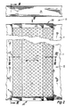
- a cable duct 15 can be attached to the side of the body 11, which is only indicated schematically in FIG. 1 and the details of which are shown in FIGS. 2 to 6.
- the wall of the corpus 11, to which the cable duct 15 is fastened is formed by a board 16.
- this is not a mandatory requirement.
- the length of the cable duct 15 corresponds essentially to the length of the corpus 11.
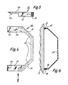
- the cable duct 15 is designed as a shaped piece 23 made of perforated sheet metal, approximately trapezoidal in cross section, cf. Fig. 6, and it is provided on its against the corpus 11 longitudinal edges 25, 26 each with a coating 27 and 28 made of an elastic material to avoid injuries from sharp edges.
- the shaped piece 23 is in each case closed off by a plastic shaped piece 30, the details of which are shown in FIGS. 4 and 5.
- This has a channel 31 adapted to the cross-sectional shape of the perforated plate 23, in which an axial end of the perforated plate 23 is fastened, e.g. by pressing with the plastic of the molding 30, by gluing or the like. 4, which contains this channel 31, continues at its ends in a deflectable hook 33 or 34, namely via an elastically deflectable intermediate piece 35 or 36 with a relatively small cross-section.
- the hooks 33, 34 are pushed at both ends of the perforated plate shaped piece 23 over the upper and the lower end of the board 16, thereby springing out by deflecting the intermediate pieces 35, 36 and then latching into the recesses 20 , 21 a.
- the relatively thin intermediate pieces 35, 36 each lie against the associated end of the board 16.
- the cable duct 15 can be moved along the body 11 in both directions, cf. arrow 40 of FIGS. 1 and 2. To unhook the hooks 33, 34 must be raised, whereupon the cable duct 15 e.g. can be removed first at its upper end, then also at its lower end. This is e.g. necessary when a new electrical device is connected, the cable of which is to be received in the cable duct 15.
- the hooks 33, 34 could also snap into place behind a projection at the upper and lower ends of the board 16, but a groove is usually easier to manufacture.
- the cross-sectional shape of the cable duct 15 can of course also be modified within wide limits.
Landscapes
- Installation Of Indoor Wiring (AREA)
Applications Claiming Priority (2)
| Application Number | Priority Date | Filing Date | Title |
|---|---|---|---|
| DE9001969U | 1990-02-20 | ||
| DE9001969 | 1990-02-20 |
Publications (1)
| Publication Number | Publication Date |
|---|---|
| EP0443389A2 true EP0443389A2 (fr) | 1991-08-28 |
Family
ID=6851188
Family Applications (1)
| Application Number | Title | Priority Date | Filing Date |
|---|---|---|---|
| EP19910101821 Withdrawn EP0443389A2 (fr) | 1990-02-20 | 1991-02-09 | Armoire |
Country Status (1)
| Country | Link |
|---|---|
| EP (1) | EP0443389A2 (fr) |
Cited By (1)
| Publication number | Priority date | Publication date | Assignee | Title |
|---|---|---|---|---|
| USD711613S1 (en) | 2013-06-11 | 2014-08-19 | A. Shawn Brenner | Amplifier stand |
-
1991
- 1991-02-09 EP EP19910101821 patent/EP0443389A2/fr not_active Withdrawn
Cited By (1)
| Publication number | Priority date | Publication date | Assignee | Title |
|---|---|---|---|---|
| USD711613S1 (en) | 2013-06-11 | 2014-08-19 | A. Shawn Brenner | Amplifier stand |
Similar Documents
| Publication | Publication Date | Title |
|---|---|---|
| DE2750871C2 (de) | Modulares elektronisches Gehäuse | |
| DE60304318T2 (de) | Befestigung einer rohrklemme | |
| EP0567844B1 (fr) | Dispositif de verrouillage pour meubles à tiroirs | |
| DE202011002758U1 (de) | Videoanzeigeeinrichtung | |
| DE2202312A1 (de) | Befestigung von schubladen od.dgl. in schreibtischen usw | |
| DE10242518A1 (de) | Aufbewahrungseinrichtung für Gegenstände an Möbeln, insbesondere Schublade oder dergleichen | |
| DE3401427C2 (de) | Türpuffer | |
| DE9317453U1 (de) | Möbelfuß für Kastenmöbel | |
| EP3727088B1 (fr) | Paroi latérale de tiroir | |
| DE202009005110U1 (de) | Möbelauszug | |
| DE9101479U1 (de) | Schrank | |
| DE1925358U (de) | Kaffeemaschine. | |
| DE69826423T2 (de) | Befestigungselement mit Greifer, insbesondere für einen Einbaubehälter, und entsprechender Einbaubehälter | |
| DE202017101022U1 (de) | Hohlkammerzarge für eine Schublade, Schublade und Möbel | |
| EP1155917B1 (fr) | Trappe coulissante recouvrant une ouverture de fixation dans un profilé de gouttière de toit de véhicule | |
| DE2759349C2 (de) | Schublade aus Kunststoff | |
| DE7702843U1 (de) | Fuehrungsschiene | |
| DE2708427B2 (de) | Vorrichtung zum Verbinden von Möbelfüßen, insbesondere von Polstersitzelementen | |
| DE2839974A1 (de) | Rahmenloser bildtraeger | |
| DE3523690A1 (de) | Hakenkern zum zusammenbau von profilteilen | |
| DE102024004527A1 (de) | Energieführungsketten und/oder Kabelführungskette | |
| AT392374B (de) | Kabeltasse | |
| DE102024102912A1 (de) | Magnetadapter | |
| DE2008551C (de) | Aus einem Kunststoff bestehende Gehäuse- und Befestigungsanordnung insbesondere für Gesprächszähler in Fernsprechamtern | |
| DE29711475U1 (de) | Schublade |
Legal Events
| Date | Code | Title | Description |
|---|---|---|---|
| PUAI | Public reference made under article 153(3) epc to a published international application that has entered the european phase |
Free format text: ORIGINAL CODE: 0009012 |
|
| AK | Designated contracting states |
Kind code of ref document: A2 Designated state(s): BE CH DE ES FR GB IT LI NL |
|
| STAA | Information on the status of an ep patent application or granted ep patent |
Free format text: STATUS: THE APPLICATION IS DEEMED TO BE WITHDRAWN |
|
| 18D | Application deemed to be withdrawn |
Effective date: 19930301 |