EP0443389A2 - Cabinet - Google Patents
Cabinet Download PDFInfo
- Publication number
- EP0443389A2 EP0443389A2 EP19910101821 EP91101821A EP0443389A2 EP 0443389 A2 EP0443389 A2 EP 0443389A2 EP 19910101821 EP19910101821 EP 19910101821 EP 91101821 A EP91101821 A EP 91101821A EP 0443389 A2 EP0443389 A2 EP 0443389A2
- Authority
- EP
- European Patent Office
- Prior art keywords
- cable duct
- cabinet
- cabinet according
- recess
- projection
- Prior art date
- Legal status (The legal status is an assumption and is not a legal conclusion. Google has not performed a legal analysis and makes no representation as to the accuracy of the status listed.)
- Withdrawn
Links
- 238000010137 moulding (plastic) Methods 0.000 claims description 3
- 230000000295 complement effect Effects 0.000 claims description 2
- 239000002184 metal Substances 0.000 claims description 2
- 238000004519 manufacturing process Methods 0.000 description 2
- 238000012986 modification Methods 0.000 description 2
- 230000004048 modification Effects 0.000 description 2
- 238000004026 adhesive bonding Methods 0.000 description 1
- 239000011248 coating agent Substances 0.000 description 1
- 238000000576 coating method Methods 0.000 description 1
- 230000006378 damage Effects 0.000 description 1
- 238000011161 development Methods 0.000 description 1
- 230000018109 developmental process Effects 0.000 description 1
- 239000013013 elastic material Substances 0.000 description 1
- 238000007373 indentation Methods 0.000 description 1
- 238000009434 installation Methods 0.000 description 1
- 238000000465 moulding Methods 0.000 description 1
- 125000006850 spacer group Chemical group 0.000 description 1
Images


Classifications
-
- A—HUMAN NECESSITIES
- A47—FURNITURE; DOMESTIC ARTICLES OR APPLIANCES; COFFEE MILLS; SPICE MILLS; SUCTION CLEANERS IN GENERAL
- A47B—TABLES; DESKS; OFFICE FURNITURE; CABINETS; DRAWERS; GENERAL DETAILS OF FURNITURE
- A47B21/00—Tables or desks for office equipment, e.g. typewriters, keyboards
- A47B21/06—Tables or desks for office equipment, e.g. typewriters, keyboards characterised by means for holding, fastening or concealing cables
-
- A—HUMAN NECESSITIES
- A47—FURNITURE; DOMESTIC ARTICLES OR APPLIANCES; COFFEE MILLS; SPICE MILLS; SUCTION CLEANERS IN GENERAL
- A47B—TABLES; DESKS; OFFICE FURNITURE; CABINETS; DRAWERS; GENERAL DETAILS OF FURNITURE
- A47B63/00—Cabinets, racks or shelf units, specially adapted for storing books, documents, forms, or the like
-
- A—HUMAN NECESSITIES
- A47—FURNITURE; DOMESTIC ARTICLES OR APPLIANCES; COFFEE MILLS; SPICE MILLS; SUCTION CLEANERS IN GENERAL
- A47B—TABLES; DESKS; OFFICE FURNITURE; CABINETS; DRAWERS; GENERAL DETAILS OF FURNITURE
- A47B81/00—Cabinets or racks specially adapted for other particular purposes, e.g. for storing guns or skis
Definitions
- the invention relates to a cabinet and in particular a side cabinet.
- Such cabinets are e.g. Employed at desks to create more space for storing files and other documents, or they serve as individual cupboards for the same purpose.
- An object of the invention is seen in improving such cabinets.
- a cable duct which is adapted to the height of the corpus and which is provided at least at one end with at least one deflectable hook for engaging in the recess or with the projection. Due to the fact that the deflectable hook can engage, for example, in the recess and can preferably snap into place there, fastening and dismantling of such a cable duct are extremely simple. Such a cable duct can also be displaced on the corpus as far as the depressions or projections on it extend. So you can summarize cables very easily and bundle in the cable duct or also take new cables into it.
- the cable duct is designed with great advantage so that its wall is made of perforated plate. This also causes electromagnetic shielding.
- a very simple embodiment also results from the fact that the at least one deflectable hook is designed as a component of a plastic molding which engages over the axial end of the perforated plate.
- the plastic molding ensures that the user cannot injure himself at the ends of the perforated plate forming the cable duct.
- a cable duct for hanging on the side wall of a piece of furniture which is characterized in that it has at its upper and lower ends each with at least one preferably elastically deflectable hook for releasably hanging on one of these hooks approximately complementary recess or a corresponding projection of the piece of furniture is provided.
- Fig. 1 shows schematically a - here designed as a side cabinet - cabinet 10 with a body 11, which is mounted on four trailing rollers 12, of which only two are visible in Fig. 1. Above the body 11, and separated from it by a gap 13, there is a cover plate 14 which is fastened to the body 11 by means of spacers 17 (FIG. 3).
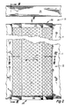
- a cable duct 15 can be attached to the side of the body 11, which is only indicated schematically in FIG. 1 and the details of which are shown in FIGS. 2 to 6.
- the wall of the corpus 11, to which the cable duct 15 is fastened is formed by a board 16.
- this is not a mandatory requirement.
- the length of the cable duct 15 corresponds essentially to the length of the corpus 11.
- the cable duct 15 is designed as a shaped piece 23 made of perforated sheet metal, approximately trapezoidal in cross section, cf. Fig. 6, and it is provided on its against the corpus 11 longitudinal edges 25, 26 each with a coating 27 and 28 made of an elastic material to avoid injuries from sharp edges.
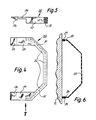
- the shaped piece 23 is in each case closed off by a plastic shaped piece 30, the details of which are shown in FIGS. 4 and 5.
- This has a channel 31 adapted to the cross-sectional shape of the perforated plate 23, in which an axial end of the perforated plate 23 is fastened, e.g. by pressing with the plastic of the molding 30, by gluing or the like. 4, which contains this channel 31, continues at its ends in a deflectable hook 33 or 34, namely via an elastically deflectable intermediate piece 35 or 36 with a relatively small cross-section.
- the hooks 33, 34 are pushed at both ends of the perforated plate shaped piece 23 over the upper and the lower end of the board 16, thereby springing out by deflecting the intermediate pieces 35, 36 and then latching into the recesses 20 , 21 a.
- the relatively thin intermediate pieces 35, 36 each lie against the associated end of the board 16.
- the cable duct 15 can be moved along the body 11 in both directions, cf. arrow 40 of FIGS. 1 and 2. To unhook the hooks 33, 34 must be raised, whereupon the cable duct 15 e.g. can be removed first at its upper end, then also at its lower end. This is e.g. necessary when a new electrical device is connected, the cable of which is to be received in the cable duct 15.
- the hooks 33, 34 could also snap into place behind a projection at the upper and lower ends of the board 16, but a groove is usually easier to manufacture.
- the cross-sectional shape of the cable duct 15 can of course also be modified within wide limits.
Landscapes
- Installation Of Indoor Wiring (AREA)
Abstract
Description
Die Erfindung betrifft einen Schrank und insbesondere einen Beistellschrank.The invention relates to a cabinet and in particular a side cabinet.
Derartige Schränke werden z.B. an Schreibtische angestellt, um mehr Platz für die Aufbewahrung von Akten und sonstigen Unterlagen zu schaffen, oder sie dienen als Einzelschränke zum gleichen Zweck.Such cabinets are e.g. Employed at desks to create more space for storing files and other documents, or they serve as individual cupboards for the same purpose.
Eine Aufgabe der Erfindung wird darin gesehen, derartige Schränke zu verbessern.An object of the invention is seen in improving such cabinets.
Nach der Erfindung wird diese Aufgabe gelöst durch die im Anspruch 1 angegebenen Maßnahmen. Durch die Vertiefungen an Ober- und Unterseite des Corpus wird es in einfacher Weise möglich, dort Zusatzteile zu befestigen, und zwar an verschiedenen Stellen, entsprechend den jeweiligen Notwendigkeiten.According to the invention, this object is achieved by the measures specified in claim 1. The indentations on the top and bottom of the corpus make it easy to attach additional parts there, in different places, depending on the particular needs.
Mit besonderem Vorteil geht man dabei so vor, daß ein an die Höhe des Corpus angepaßter Kabelkanal vorgesehen ist, welcher an mindestens einem Ende mit mindestens einem auslenkbaren Haken zum Eingriff in die Vertiefung bzw. mit dem Vorsprung versehen ist. Dadurch, daß der auslenkbare Haken z.B. in die Vertiefung eingreifen und dort bevorzugt elastisch einrasten kann, werden Befestigung und Demontage eines solchen Kabelkanals äußerst einfach. Auch kann ein solcher Kabelkanal so weit am Corpus verschoben werden, wie die Vertiefungen oder Vorsprünge an diesem reichen. Man kann also Kabel sehr einfach zusammenfassen und im Kabelkanal bündeln oder auch neue Kabel in diesen aufnehmen.It is particularly advantageous to provide a cable duct which is adapted to the height of the corpus and which is provided at least at one end with at least one deflectable hook for engaging in the recess or with the projection. Due to the fact that the deflectable hook can engage, for example, in the recess and can preferably snap into place there, fastening and dismantling of such a cable duct are extremely simple. Such a cable duct can also be displaced on the corpus as far as the depressions or projections on it extend. So you can summarize cables very easily and bundle in the cable duct or also take new cables into it.
Dabei wird der Kabelkanal mit großem Vorteil so ausgebildet, daß seine Wand aus Lochblech ausgebildet ist. Dies bewirkt gleichzeitig eine elektromagnetische Abschirmung.The cable duct is designed with great advantage so that its wall is made of perforated plate. This also causes electromagnetic shielding.
Eine sehr einfache Ausgestaltung ergibt sich ferner dadurch, daß der mindestens eine auslenkbare Haken als Bestandteil eines Kunststofformstücks ausgebildet ist, welches das axiale Ende des Lochblechs übergreift. So ergibt sich eine äußerst preiswerte Ausführung des Kabelkanals, die sehr einfach herzustellen und dabei außerordentlich praxisgerecht ist. Gleichzeitig wird durch das Kunststofformstück erreicht, daß sich der Benutzer nicht an den Enden des den Kabelkanal bildenden Lochblechs verletzen kann.A very simple embodiment also results from the fact that the at least one deflectable hook is designed as a component of a plastic molding which engages over the axial end of the perforated plate. This results in an extremely inexpensive version of the cable duct, which is very easy to manufacture and is extremely practical. At the same time, the plastic molding ensures that the user cannot injure himself at the ends of the perforated plate forming the cable duct.
Eine weitere Lösung der gestellten Aufgabe ergibt sich durch einen Kabelkanal zum Einhängen an der Seitenwand eines Möbelstücks, welcher dadurch gekennzeichnet ist, daß er an seinem oberen und an seinem unteren Ende jeweils mit mindestens einem vorzugsweise elastisch auslenkbaren Haken zum lösbaren Einhängen an einer zu diesem Haken etwa komplementäre Vertiefung oder einem entsprechenden Vorsprung des Möbelstücks versehen ist.Another solution to the problem is provided by a cable duct for hanging on the side wall of a piece of furniture, which is characterized in that it has at its upper and lower ends each with at least one preferably elastically deflectable hook for releasably hanging on one of these hooks approximately complementary recess or a corresponding projection of the piece of furniture is provided.
Weitere Einzelheiten und vorteilhafte Weiterbildungen der Erfindung ergeben sich aus dem im folgenden beschriebenen und in der Zeichnung dargestellten, in keiner Weise als Einschränkung der Erfindung zu verstehenden Ausführungsbeispiel, sowie aus den übrigen Unteransprüchen. Es zeigt:
- Fig. 1
- eine raumbildliche Übersichtsdarstellung, welche einen erfindungsgemäßen Schrank und einen an diesem befestigten Kabelkanal zeigt,
- Fig. 2
- eine Vorderansicht des Kabelkanals der Fig. 1,
- Fig. 3
- eine Seitenansicht des Kabelkanals, gesehen längs der Linie III-III der Fig. 2,
- Fig. 4
- eine Draufsicht auf das obere Ende des Kabelkanals, gesehen in Richtung des Pfeiles IV der Fig. 2 und 3,
- Fig. 5
- eine teilweise im Schnitt dargestellte Seitenansicht, gesehen längs des Pfeiles V der Fig. 4, und
- Fig. 6
- einen Schnitt, gesehen längs der Linie VI-VI der Fig. 2.
- Fig. 1
- 3 shows a spatial overview which shows a cabinet according to the invention and a cable duct attached to it,
- Fig. 2
- 2 shows a front view of the cable duct of FIG. 1,
- Fig. 3
- a side view of the cable duct, seen along the line III-III of Fig. 2,
- Fig. 4
- a plan view of the upper end of the cable duct, seen in the direction of arrow IV of FIGS. 2 and 3,
- Fig. 5
- a partial side view shown in section, seen along the arrow V of Fig. 4, and
- Fig. 6
- a section, seen along the line VI-VI of Fig. 2nd
Fig. 1 zeigt schematisch einen - hier als Beistellschrank ausgebildeten - Schrank 10 mit einem Corpus 11, das auf vier Nachlaufrollen 12 gelagert ist, von denen in Fig. 1 nur zwei sichtbar sind. Oberhalb des Corpus 11, und von diesem durch einen Spalt 13 getrennt, befindet sich eine Deckplatte 14, die am Corpus 11 mittels Distanzstücken 17 (Fig. 3) befestigt ist.Fig. 1 shows schematically a - here designed as a side cabinet -
Seitlich am Corpus 11 kann ein Kabelkanal 15 befestigt werden, der in Fig. 1 nur schematisch angedeutet ist und dessen Einzelheiten in den Figuren 2 bis 6 dargestellt sind. Bei der in Fig. 1 dargestellten Ausführungsform wird die Wand des Corpus 11, an welcher der Kabelkanal 15 befestigt ist, von einem Brett 16 gebildet. Dies ist jedoch keine zwingende Voraussetzung.A
Wie die Fig. 2 und 3 zeigen, entspricht die Länge des Kabelkanals 15 im wesentlichen der Länge des Corpus 11. Gemäß Fig. 3 ist am oberen und unteren Rand des Brettes 16 eine nutartige Vertiefung 20 (oben) bzw. 21 (unten) ausgebildet, und zwar im Abstand von der Außenseite des Corpus 11. Wie Fig. 1 zeigt, können sich diese Vertiefungen um den gesamten Umfang des Corpus 11 erstrecken, oder wenigstens dort, wo mit der Anbringung eines Kabelkanals zu rechnen ist.2 and 3 show, the length of the
Der Kabelkanal 15 ist als Formstück 23 aus Lochblech ausgebildet, im Querschnitt etwa trapezförmig, vgl. Fig. 6, und er ist an seinen gegen das Corpus 11 anliegenden Längskanten 25, 26 jeweils mit einem Überzug 27 bzw. 28 aus einem elastischen Werkstoff versehen, um dort Verletzungen durch scharfe Kanten zu vermeiden.The
An seinen Längsenden ist das Formstück 23 jeweils durch ein Kunststoff-Formstück 30 abgeschlossen, dessen Einzelheiten aus den Figuren 4 und 5 hervorgehen. Dieses hat einen der Querschnittsform des Lochblechs 23 angepaßten Kanal 31, in welchem ein axiales Ende des Lochblechs 23 befestigt ist, z.B. durch Umpressen mit dem Kunststoff des Formstücks 30, durch Kleben oder dergleichen. Das in der Draufsicht gemäß Fig. 4 trapezfürmige Teil 32, das diesen Kanal 31 enthält, setzt sich an seinen Enden jeweils fort in einen auslenkbaren Haken 33 bzw. 34, und zwar über ein elastisch auslenkbares Zwischenstück 35 bzw. 36 mit relativ geringem Querschnitt.At its longitudinal ends, the
Bei der Montage des Kabelkanals 15 werden die Haken 33, 34 an beiden Enden des Lochblech-Formstücks 23 über das obere bzw. das untere Ende des Brettes 16 geschoben, federn dabei durch Auslenkung der Zwischenstücke 35, 36 aus und rasten dann in den Vertiefungen 20, 21 ein. Die relativ dünnen Zwischenstücke 35, 36 legen sich dabei jeweils gegen das zugeordnete Ende des Bretts 16.During the assembly of the
Der Kabelkanal 15 kann längs des Corpus 11 in beiden Richtungen verschoben werden, vgl. den Pfeil 40 der Fig. 1 und 2. Zum Aushängen müssen die Haken 33, 34 angehoben werden, worauf der Kabelkanal 15 z.B. zunächst an seinem oberen Ende abgenommen werden kann, anschließend auch an seinem unteren Ende. Dies ist z.B. dann notwendig, wenn ein neues elektrisches Gerät angeschlossen wird, dessen Kabel in den Kabelkanal 15 aufgenommen werden soll.The
Durch den Spalt 13 ist es möglich, an der Deckplatte 14 Schraubzwingen zu befestigen. Naturgemäß sind im Rahmen der Erfindung vielfältige Abwandlungen und Modifikationen möglich. Z.B. könnten die Haken 33, 34 auch hinter einem Vorsprung am oberen und unteren Ende des Bretts 16 einrasten, doch ist eine Nut meist einfacher zu fertigen. Auch die Querschnittsform des Kabelkanals 15 ist selbstverständlich in weiten Grenzen modifizierbar.Through the
Claims (11)
Applications Claiming Priority (2)
| Application Number | Priority Date | Filing Date | Title |
|---|---|---|---|
| DE9001969U | 1990-02-20 | ||
| DE9001969 | 1990-02-20 |
Publications (1)
| Publication Number | Publication Date |
|---|---|
| EP0443389A2 true EP0443389A2 (en) | 1991-08-28 |
Family
ID=6851188
Family Applications (1)
| Application Number | Title | Priority Date | Filing Date |
|---|---|---|---|
| EP19910101821 Withdrawn EP0443389A2 (en) | 1990-02-20 | 1991-02-09 | Cabinet |
Country Status (1)
| Country | Link |
|---|---|
| EP (1) | EP0443389A2 (en) |
Cited By (1)
| Publication number | Priority date | Publication date | Assignee | Title |
|---|---|---|---|---|
| USD711613S1 (en) | 2013-06-11 | 2014-08-19 | A. Shawn Brenner | Amplifier stand |
-
1991
- 1991-02-09 EP EP19910101821 patent/EP0443389A2/en not_active Withdrawn
Cited By (1)
| Publication number | Priority date | Publication date | Assignee | Title |
|---|---|---|---|---|
| USD711613S1 (en) | 2013-06-11 | 2014-08-19 | A. Shawn Brenner | Amplifier stand |
Similar Documents
| Publication | Publication Date | Title |
|---|---|---|
| DE2750871C2 (en) | Modular electronic housing | |
| DE60304318T2 (en) | ATTACHING A TUBE CLAMP | |
| EP0567844B1 (en) | Locking device for a drawer cabinet | |
| DE202011002758U1 (en) | Video display device | |
| DE2202312A1 (en) | FASTENING OF DRAWERS OR DGL. IN DESKS ETC. | |
| DE10242518A1 (en) | Drawer has flexible partition which divides its internal space consisting of strip of textile or rubber mounted on posts which fit into holes in pattern in drawer base | |
| DE3401427C2 (en) | Door buffer | |
| DE9317453U1 (en) | Furniture foot for cabinet furniture | |
| EP3727088B1 (en) | Drawer side wall | |
| DE202009005110U1 (en) | An extendable | |
| DE9101479U1 (en) | Wardrobe | |
| DE1925358U (en) | COFFEE MACHINE. | |
| DE69826423T2 (en) | Fastening element with gripper, in particular for a built-in container, and corresponding installation container | |
| DE202017101022U1 (en) | Hollow chamber frame for a drawer, drawer and furniture | |
| EP1155917B1 (en) | Slide for closing an opening for securing in a cover strip of a vehicle roof rack channel | |
| DE2759349C2 (en) | Plastic drawer | |
| DE7702843U1 (en) | GUIDE RAIL | |
| DE2708427B2 (en) | Device for connecting furniture feet, in particular upholstered seating elements | |
| DE2839974A1 (en) | Frameless picture holder with front and back plates - has special retaining clips allowing easy removal of cover without damage | |
| DE3523690A1 (en) | Hook core for joining profiled parts | |
| DE102024004527A1 (en) | Energy guiding chains and/or cable guiding chains | |
| AT392374B (en) | CABLE CAB | |
| DE102024102912A1 (en) | Magnetic adapter | |
| DE2008551C (en) | Housing and fastening arrangement consisting of a plastic, in particular for call counters in telephone exchanges | |
| DE29711475U1 (en) | drawer |
Legal Events
| Date | Code | Title | Description |
|---|---|---|---|
| PUAI | Public reference made under article 153(3) epc to a published international application that has entered the european phase |
Free format text: ORIGINAL CODE: 0009012 |
|
| AK | Designated contracting states |
Kind code of ref document: A2 Designated state(s): BE CH DE ES FR GB IT LI NL |
|
| STAA | Information on the status of an ep patent application or granted ep patent |
Free format text: STATUS: THE APPLICATION IS DEEMED TO BE WITHDRAWN |
|
| 18D | Application deemed to be withdrawn |
Effective date: 19930301 |