EP0442941B1 - Materiau d'etancheite, boitier utilisant ce materiau et realisation du boitier - Google Patents
Materiau d'etancheite, boitier utilisant ce materiau et realisation du boitier Download PDFInfo
- Publication number
- EP0442941B1 EP0442941B1 EP89912862A EP89912862A EP0442941B1 EP 0442941 B1 EP0442941 B1 EP 0442941B1 EP 89912862 A EP89912862 A EP 89912862A EP 89912862 A EP89912862 A EP 89912862A EP 0442941 B1 EP0442941 B1 EP 0442941B1
- Authority
- EP
- European Patent Office
- Prior art keywords
- sealing material
- sealing
- substrate
- less
- sleeve
- Prior art date
- Legal status (The legal status is an assumption and is not a legal conclusion. Google has not performed a legal analysis and makes no representation as to the accuracy of the status listed.)
- Expired - Lifetime
Links
- 239000003566 sealing material Substances 0.000 title claims abstract description 110
- 238000000034 method Methods 0.000 title claims abstract description 27
- 238000007789 sealing Methods 0.000 claims abstract description 65
- 239000000758 substrate Substances 0.000 claims abstract description 46
- 230000006835 compression Effects 0.000 claims abstract description 21
- 238000007906 compression Methods 0.000 claims abstract description 21
- 239000000203 mixture Substances 0.000 claims description 36
- 229920001400 block copolymer Polymers 0.000 claims description 30
- 239000000463 material Substances 0.000 claims description 28
- 239000003921 oil Substances 0.000 claims description 23
- 229920000642 polymer Polymers 0.000 claims description 16
- 229920001577 copolymer Polymers 0.000 claims description 14
- 239000004606 Fillers/Extenders Substances 0.000 claims description 11
- -1 styrene-ethylene-butylene-styrene Chemical class 0.000 claims description 10
- 238000003860 storage Methods 0.000 claims description 9
- 239000004721 Polyphenylene oxide Substances 0.000 claims description 7
- 229920006380 polyphenylene oxide Polymers 0.000 claims description 7
- 230000007613 environmental effect Effects 0.000 claims description 6
- 239000007788 liquid Substances 0.000 claims description 6
- 230000009477 glass transition Effects 0.000 claims description 5
- 238000013017 mechanical damping Methods 0.000 claims description 5
- 238000001746 injection moulding Methods 0.000 claims description 4
- 229920006122 polyamide resin Polymers 0.000 claims description 4
- 229920006132 styrene block copolymer Polymers 0.000 claims description 4
- 239000002480 mineral oil Substances 0.000 claims 2
- 235000010446 mineral oil Nutrition 0.000 claims 2
- 239000000499 gel Substances 0.000 description 56
- 238000009434 installation Methods 0.000 description 12
- PPBRXRYQALVLMV-UHFFFAOYSA-N Styrene Chemical compound C=CC1=CC=CC=C1 PPBRXRYQALVLMV-UHFFFAOYSA-N 0.000 description 10
- 230000035515 penetration Effects 0.000 description 9
- 238000011084 recovery Methods 0.000 description 9
- 238000012360 testing method Methods 0.000 description 8
- 229920000428 triblock copolymer Polymers 0.000 description 8
- 238000002156 mixing Methods 0.000 description 7
- 238000005259 measurement Methods 0.000 description 6
- 230000001070 adhesive effect Effects 0.000 description 5
- 238000013461 design Methods 0.000 description 5
- 230000014759 maintenance of location Effects 0.000 description 5
- 238000009864 tensile test Methods 0.000 description 5
- 239000000853 adhesive Substances 0.000 description 4
- 230000015572 biosynthetic process Effects 0.000 description 4
- 230000008859 change Effects 0.000 description 4
- 238000004132 cross linking Methods 0.000 description 4
- 238000005755 formation reaction Methods 0.000 description 4
- 238000010438 heat treatment Methods 0.000 description 4
- 238000002844 melting Methods 0.000 description 4
- 230000008018 melting Effects 0.000 description 4
- 229920001935 styrene-ethylene-butadiene-styrene Polymers 0.000 description 4
- 229920002633 Kraton (polymer) Polymers 0.000 description 3
- 238000005520 cutting process Methods 0.000 description 3
- 230000005489 elastic deformation Effects 0.000 description 3
- 229920001971 elastomer Polymers 0.000 description 3
- 238000009472 formulation Methods 0.000 description 3
- 230000007246 mechanism Effects 0.000 description 3
- 239000000243 solution Substances 0.000 description 3
- 239000004215 Carbon black (E152) Substances 0.000 description 2
- RTZKZFJDLAIYFH-UHFFFAOYSA-N Diethyl ether Chemical compound CCOCC RTZKZFJDLAIYFH-UHFFFAOYSA-N 0.000 description 2
- 239000004729 Noryl GTX Substances 0.000 description 2
- 239000004793 Polystyrene Substances 0.000 description 2
- 230000009471 action Effects 0.000 description 2
- 239000000654 additive Substances 0.000 description 2
- 239000004411 aluminium Substances 0.000 description 2
- 229910052782 aluminium Inorganic materials 0.000 description 2
- XAGFODPZIPBFFR-UHFFFAOYSA-N aluminium Chemical compound [Al] XAGFODPZIPBFFR-UHFFFAOYSA-N 0.000 description 2
- 239000003963 antioxidant agent Substances 0.000 description 2
- 238000009835 boiling Methods 0.000 description 2
- 230000006378 damage Effects 0.000 description 2
- 150000001993 dienes Chemical class 0.000 description 2
- 230000000694 effects Effects 0.000 description 2
- 229930195733 hydrocarbon Natural products 0.000 description 2
- 150000002430 hydrocarbons Chemical class 0.000 description 2
- 239000011159 matrix material Substances 0.000 description 2
- 229910052751 metal Inorganic materials 0.000 description 2
- 239000002184 metal Substances 0.000 description 2
- 230000004048 modification Effects 0.000 description 2
- 238000012986 modification Methods 0.000 description 2
- 230000000704 physical effect Effects 0.000 description 2
- 229920002959 polymer blend Polymers 0.000 description 2
- 229920002223 polystyrene Polymers 0.000 description 2
- 229920000346 polystyrene-polyisoprene block-polystyrene Polymers 0.000 description 2
- 230000000750 progressive effect Effects 0.000 description 2
- 239000005060 rubber Substances 0.000 description 2
- 238000000926 separation method Methods 0.000 description 2
- 238000010008 shearing Methods 0.000 description 2
- 239000003381 stabilizer Substances 0.000 description 2
- 239000011800 void material Substances 0.000 description 2
- ROGIWVXWXZRRMZ-UHFFFAOYSA-N 2-methylbuta-1,3-diene;styrene Chemical compound CC(=C)C=C.C=CC1=CC=CC=C1 ROGIWVXWXZRRMZ-UHFFFAOYSA-N 0.000 description 1
- VGGSQFUCUMXWEO-UHFFFAOYSA-N Ethene Chemical compound C=C VGGSQFUCUMXWEO-UHFFFAOYSA-N 0.000 description 1
- 239000005977 Ethylene Substances 0.000 description 1
- 229920002302 Nylon 6,6 Polymers 0.000 description 1
- 229920003171 Poly (ethylene oxide) Polymers 0.000 description 1
- 239000004743 Polypropylene Substances 0.000 description 1
- 241000736032 Sabia <angiosperm> Species 0.000 description 1
- 239000002174 Styrene-butadiene Substances 0.000 description 1
- 238000004458 analytical method Methods 0.000 description 1
- 125000003118 aryl group Chemical group 0.000 description 1
- 230000000712 assembly Effects 0.000 description 1
- 238000000429 assembly Methods 0.000 description 1
- 238000005452 bending Methods 0.000 description 1
- 230000009286 beneficial effect Effects 0.000 description 1
- 230000000903 blocking effect Effects 0.000 description 1
- MTAZNLWOLGHBHU-UHFFFAOYSA-N butadiene-styrene rubber Chemical compound C=CC=C.C=CC1=CC=CC=C1 MTAZNLWOLGHBHU-UHFFFAOYSA-N 0.000 description 1
- 238000012512 characterization method Methods 0.000 description 1
- 238000001816 cooling Methods 0.000 description 1
- 230000007797 corrosion Effects 0.000 description 1
- 238000005260 corrosion Methods 0.000 description 1
- 238000002425 crystallisation Methods 0.000 description 1
- 230000007547 defect Effects 0.000 description 1
- 229920000359 diblock copolymer Polymers 0.000 description 1
- 238000006073 displacement reaction Methods 0.000 description 1
- 239000000428 dust Substances 0.000 description 1
- 239000000806 elastomer Substances 0.000 description 1
- 238000002474 experimental method Methods 0.000 description 1
- 238000001125 extrusion Methods 0.000 description 1
- 239000004744 fabric Substances 0.000 description 1
- 239000003063 flame retardant Substances 0.000 description 1
- 239000012530 fluid Substances 0.000 description 1
- 239000008240 homogeneous mixture Substances 0.000 description 1
- 239000012943 hotmelt Substances 0.000 description 1
- 239000004615 ingredient Substances 0.000 description 1
- 239000003112 inhibitor Substances 0.000 description 1
- 238000003780 insertion Methods 0.000 description 1
- 230000037431 insertion Effects 0.000 description 1
- 239000011872 intimate mixture Substances 0.000 description 1
- 230000018984 mastication Effects 0.000 description 1
- 238000010077 mastication Methods 0.000 description 1
- 238000011326 mechanical measurement Methods 0.000 description 1
- 238000010128 melt processing Methods 0.000 description 1
- 239000012768 molten material Substances 0.000 description 1
- 230000010355 oscillation Effects 0.000 description 1
- 230000003534 oscillatory effect Effects 0.000 description 1
- 239000008188 pellet Substances 0.000 description 1
- 238000005191 phase separation Methods 0.000 description 1
- 229920001083 polybutene Polymers 0.000 description 1
- 229920001748 polybutylene Polymers 0.000 description 1
- 229920001955 polyphenylene ether Polymers 0.000 description 1
- 229920001155 polypropylene Polymers 0.000 description 1
- 238000005381 potential energy Methods 0.000 description 1
- 238000002360 preparation method Methods 0.000 description 1
- 238000009747 press moulding Methods 0.000 description 1
- 230000005855 radiation Effects 0.000 description 1
- 238000003847 radiation curing Methods 0.000 description 1
- 230000002787 reinforcement Effects 0.000 description 1
- 230000008439 repair process Effects 0.000 description 1
- 239000011347 resin Substances 0.000 description 1
- 229920005989 resin Polymers 0.000 description 1
- 230000004044 response Effects 0.000 description 1
- 238000000518 rheometry Methods 0.000 description 1
- 239000000565 sealant Substances 0.000 description 1
- 230000035945 sensitivity Effects 0.000 description 1
- 229920002379 silicone rubber Polymers 0.000 description 1
- 239000004945 silicone rubber Substances 0.000 description 1
- 239000007787 solid Substances 0.000 description 1
- 239000002904 solvent Substances 0.000 description 1
- 238000001228 spectrum Methods 0.000 description 1
- 229910001220 stainless steel Inorganic materials 0.000 description 1
- 239000010935 stainless steel Substances 0.000 description 1
- 239000011115 styrene butadiene Substances 0.000 description 1
- 229920003048 styrene butadiene rubber Polymers 0.000 description 1
- 229920000468 styrene butadiene styrene block copolymer Polymers 0.000 description 1
- 238000010998 test method Methods 0.000 description 1
- 125000000383 tetramethylene group Chemical group [H]C([H])([*:1])C([H])([H])C([H])([H])C([H])([H])[*:2] 0.000 description 1
- 229920001169 thermoplastic Polymers 0.000 description 1
- 229920002725 thermoplastic elastomer Polymers 0.000 description 1
- 239000004416 thermosoftening plastic Substances 0.000 description 1
- 230000001052 transient effect Effects 0.000 description 1
- 230000007704 transition Effects 0.000 description 1
- 239000003190 viscoelastic substance Substances 0.000 description 1
Images


Classifications
-
- H—ELECTRICITY
- H02—GENERATION; CONVERSION OR DISTRIBUTION OF ELECTRIC POWER
- H02G—INSTALLATION OF ELECTRIC CABLES OR LINES, OR OF COMBINED OPTICAL AND ELECTRIC CABLES OR LINES
- H02G15/00—Cable fittings
- H02G15/08—Cable junctions
- H02G15/18—Cable junctions protected by sleeves, e.g. for communication cable
- H02G15/1806—Heat shrinkable sleeves
- H02G15/1813—Wraparound or slotted sleeves
-
- H—ELECTRICITY
- H02—GENERATION; CONVERSION OR DISTRIBUTION OF ELECTRIC POWER
- H02G—INSTALLATION OF ELECTRIC CABLES OR LINES, OR OF COMBINED OPTICAL AND ELECTRIC CABLES OR LINES
- H02G15/00—Cable fittings
- H02G15/08—Cable junctions
- H02G15/18—Cable junctions protected by sleeves, e.g. for communication cable
-
- C—CHEMISTRY; METALLURGY
- C08—ORGANIC MACROMOLECULAR COMPOUNDS; THEIR PREPARATION OR CHEMICAL WORKING-UP; COMPOSITIONS BASED THEREON
- C08L—COMPOSITIONS OF MACROMOLECULAR COMPOUNDS
- C08L53/00—Compositions of block copolymers containing at least one sequence of a polymer obtained by reactions only involving carbon-to-carbon unsaturated bonds; Compositions of derivatives of such polymers
- C08L53/02—Compositions of block copolymers containing at least one sequence of a polymer obtained by reactions only involving carbon-to-carbon unsaturated bonds; Compositions of derivatives of such polymers of vinyl-aromatic monomers and conjugated dienes
-
- H—ELECTRICITY
- H01—ELECTRIC ELEMENTS
- H01R—ELECTRICALLY-CONDUCTIVE CONNECTIONS; STRUCTURAL ASSOCIATIONS OF A PLURALITY OF MUTUALLY-INSULATED ELECTRICAL CONNECTING ELEMENTS; COUPLING DEVICES; CURRENT COLLECTORS
- H01R13/00—Details of coupling devices of the kinds covered by groups H01R12/70 or H01R24/00 - H01R33/00
- H01R13/46—Bases; Cases
- H01R13/52—Dustproof, splashproof, drip-proof, waterproof, or flameproof cases
- H01R13/5216—Dustproof, splashproof, drip-proof, waterproof, or flameproof cases characterised by the sealing material, e.g. gels or resins
-
- H—ELECTRICITY
- H02—GENERATION; CONVERSION OR DISTRIBUTION OF ELECTRIC POWER
- H02G—INSTALLATION OF ELECTRIC CABLES OR LINES, OR OF COMBINED OPTICAL AND ELECTRIC CABLES OR LINES
- H02G15/00—Cable fittings
- H02G15/013—Sealing means for cable inlets
Definitions
- This invention relates to a re-enterable closure assembly for enclosing an elongate substrate such as a splice between telecommunications cables, to a sealing member suitable for use in such an assembly, and for other uses, and to a sealing material useful as part of such a member and for other uses.
- the term re-enterable means that the closure can be reopened to allow access to the elongate substrate, generally without destruction or removal of the entire assembly.
- closure articles for enclosing and environmentally sealing elongate substrates for example splices in electrical cables, such as telecommunications or power cables
- a typical enclosure for an end-to-end splice between cables comprises a heat-recoverable polymeric sleeve having two open ends, which can be positioned around the splice and shrunk by heating to provide seals to the cables.
- a heat recoverable article is an article the dimensional configuration of which may be made substantially to change when subjected to heat treatment. Usually these articles recover, on heating, towards an original shape from which they have previously been deformed but the term "heat-recoverable”, as used herein, also includes an article which, on heating, adopts a new configuration, even if it has not been previously deformed.
- a dimensionally heat-stable article is one whose dimensional configuration does not substantially change when subjected to the relevant installation temperature, and one therefore that does not require configurational change such as shrinkage (as opposed to mere bending etc) for installation. It may be advantageous to avoid the heat energy required for installation of a heat-recoverable article but hitherto satisfactory seals have required heat-shrinkage.
- a typical, and commonly used wraparound closure is disclosed in British Patent No. 1155470.
- This describes a wraparound sleeve formed as an elongate sheet or split tube which is wrapped around the cable.
- the sleeve has two upstanding rails that may be secured together in abutment by a closure channel, made for example from stainless steel.
- One of the rails is usually located at one longitudinal edge of the sleeve while the other rail may be spaced from the other edge of the sleeve, the sleeve portion between said other rail and its adjacent sleeve edge forming a longitudinal flap that extends beneath the abutting rails.
- the flap thereby helps to provide environmental sealing beneath the abutment of the rails.
- the flap may be separate.
- Such a splice closure is commonly referred to in the art as "a rail and channel" closure.
- Re-enterable splice closures are also known. These are required for example where it is desirable to be able to gain access to the splice, for example for observation of faults, for repair, or for modification of the splice.
- WO 88/00603 discloses gel or gelloid compositions in accordance with the preamble of appended claim 1, which are particularly suitable for use as sealing materials.
- a sealing means that can provide a seal between a cover, such as a sleeve, and a substrate, such as a cable.
- a first aspect of the invention provides a method of environmentally protecting an elongate substrate with a cover and a sealing means comprising a sealing material having an elongation at 23°C of at least 100%, which comprises positioning the sealing means around a portion of the substrate and surrounding the substrate with the cover such that the sealing material provides a seal between the cover and the substrate, characterised in that the composition of the sealing material is selected to give a compression set as determined by ASTM 395-A5 at 70°C of less than 30%.
- the invention in a second aspect provides a sealing means for forming a seal between a cover and an elongate substrate, the sealing means comprising a sealing material having an elongation at 23°C of at least 100% and a compression set as determined by ASTM 395-A5 at 70°C of less than 30% and a substantially rigid portion.
- the invention further provides a sealing material having an elongation at 23°C of at least 100% and a compression set as determined by ASTM 395-A5 at 70°C of less than 30% and a dynamic storage modulus at 23°C and at 1Hz of less than 105 Pa (106 dynes/cm2).
- the sealing means may comprise a sealing material and a relatively (preferably substantially) rigid portion, the sealing material providing a seal between the substantially rigid portion and the cover.
- the substantially rigid portion may have a hole therethrough, through which the substrate may pass.
- the sealing material may initially be separate from the rigid portion, and may for example be wrapped around the substrate. Alternatively, it may be provided affixed to the rigid portion, for example by injection moulding.
- the sealing material may comprise a relatively hard portion and a relatively soft portion, for example harder and softer gels. The softer material may be positioned between portions of harder material and thereby be held in place.
- a compressive force may be provided on the sealing material, forcing it against the substrate, and the cover and/or the rigid portion. This may be achieved by bringing together two plates in an axial direction with respect to the substrate, causing radial displacement of sealing material to seal to the substrates and/or cover. Pairs of plates may be provided at ends of a splice case.
- a sealing means may be positioned around the substrate at two spaced apart portions thereof, for example at either side of a cable splice, and the cover positioned to bridge the two sealing means, thus for example providing a splice case around the splice.
- the closure comprises a cover, such as a sleeve, particularly a wraparound sleeve, preferably dimensionally heat-stable, sealed to the substrate by means at least of the sealing means.
- a cover such as a sleeve, particularly a wraparound sleeve, preferably dimensionally heat-stable
- the cover preferably comprises a dimensionally heat-stable sleeve which is preferably held in its closed configuration by a securing means.
- This securing means is preferably also re-openable and reusable.
- the dimensionally heat-stable sleeve may comprise a wraparound sleeve with upstanding rails.
- the securing means may comprise a clamp which can be tightened by mechanical means (such as screws or bolts) to secure the rails together. Then, all that is required to re-enter the assembly is to release (unscrew) the securing means and open the dimensionally heat-stable sleeve.
- the clamp may comprise an elongate channel that has a portion c-shaped in cross-section that can be positioned over rails of the sleeve to hold the rails together. Such a channel may be snapped over the rails radially with respect to the sleeve or slid along them longitudinally. At least one of the rails may comprise a removable part (such as a rod that engages a slot or recess in a fixed part of the rail) that locks the channel in position. The channel may engage the other rail in a hinge-like manner.
- the channel may be positioned over the rails radially, and the rod or other part positioned (for example to fill a gap between channel and fixed part of the rails) to prevent radial removal of the channel.
- This may be desirable if the channel or a part of the sleeve between the rails is to carry a gel or other sealing material since shearing action on the gel (that may result from the channel being slid longitudinally onto the rails) may be avoided.
- the channel may incorporate means, such as a longitudinally extending recess or reservoir, for retaining a gel.
- Such gel may provide a seal between the longitudinal edges of the sleeve between the rails that are brought together when the sleeve is held in its closed configuration. The gel may contact and therefore seal to end seals of the to-be-formed splice case that seal between ingoing cables and the sleeve.
- the gel reservoir may be spring loaded or other resilient means be provided to compress the gel in the desired direction.
- the dimensionally heat-stable sleeve is preferably tubular and open at both ends. It is preferably used in combination with and overlapping a said sealing means at one or each end, although a heat-recoverable sleeve may be used alternatively or additionally at one or each end. This combination can be used to enclose an in-line or butt splice between two or more cables.
- sealing material may be wrapped circumferentially around the circumference of an end portion of each heat-recoverable sleeve.
- sealing material may be internally wrapped within end portions of the heat-stable sleeve.
- a sealing strip preferably of similar material, may also be used to seal between the longitudinal edges of the wrapped heat-stable sleeve.
- the dimensionally heat-stable sleeve may be sealed to the heat-recoverable sleeves.
- the heat-recoverable sleeves need to be recovered onto the substrate, generally cables either side of a splice.
- the closure means for example the channel for a rail and channel closure, prevents such "pull away", but in the present invention it preferably extends along part only of the length of the sleeve. Hence, portions of the sleeves are not held together.
- the heat recoverable wraparound sleeves are pre-installed in the factory onto a wraparound liner by partial recovery.
- at least a length of the sleeve initially has no closure means, e.g. no rail or channel, and at least that length of the sleeve which has no closure means is pre-installed.
- This preinstallation may be carried out in the factory by temporary provision of a closure means on that portion to resist the hoop stresses of recovery.
- the installation is effected so that the wraparound opening of the sleeve and liner coincide so that the combination can still be reopened in the field.
- there is no adhesive used between the liner and sleeve so there is no bonding.
- the liner does not extend along the whole length of the sleeve.
- the heat recoverable sleeve(s) are recovered before installation of the dimensionally heat-stable sleeve.
- an insert closure means is preferably provided temporarily to hold closed that portion of the sleeve along which there is no closure, while recovery is carried out. This insert is then removed prior to installation of the dimensionally heat-stable sleeve and its securing member.
- the heat-recoverable sleeves comprise rails with a channel extending along part of their length
- the rails preferably extend along the entire length of each sleeve
- a short insert closure is preferably positioned over the remaining exposed parts of the rails to hold the sleeve closed along its entire length during recovery.
- the extra rail section, together with the short insert closure may be removed, e.g. by use of a cutting wire, after recovery, to provide a flat section onto which the dimensionally heat-stable sleeve (and its securing means) are positioned.
- the elongate substrate is branched, e.g. where it comprises two or more cables entering a splice, it may be necessary to seal the crutch of the branch region. This may be achieved using a branch-off clip in conjunction with heat-recoverable sleeves, for example as described in U.K. 1604981 or in E.P. 83302627.
- the sealing means comprises a substantially rigid portion having a hole therethrough for each branching cable. Each cable is sealed to its respective hole by the sealing material.
- Splice closures made according to the invention may advantageously be secured to a stable object e.g. to a wall. This may conveniently be carried out by fixing the securing means to the wall.
- This invention also relates to a sealing material such as a gel (which term herein includes gelloid) composition.
- gel is meant a liquid-extended polymer composition preferably having a cone penetration value (measured by a modified version of ASTM D217, as described below) within the range from 30 to 400 (10 ⁇ 1 millimetres); an ultimate elongation (measured by ASTM D412 as described below) greater than 100%, with substantially elastic deformation to an elongation of at least 100%.
- the composition may either contain three-dimensional cross-linked molecular formations or may merely behave as if it contained such molecular formations (gelloids). Two or more gels etc. of different properties may be used together, for example a softer gel to provide a seal and a harder gel to locate the softer gel and to apply pressure to it.
- the invention is more particularly concerned with gel or gelloid compositions comprising a block copolymer having relatively hard blocks and relatively elastomeric blocks (e.g. hydrogenated rubber blocks) examples of such copolymers including styrene-diene block copolymers (linear or radial) for example styrene-butadiene or styreneisoprene diblock or triblock copolymers, or styrene-ethylene-butylenestyrene triblock copolymers.
- styrene-diene block copolymers linear or radial
- styrene-butadiene or styreneisoprene diblock or triblock copolymers or styrene-ethylene-butylenestyrene triblock copolymers.
- Oil-extended compositions of block copolymers are known, for example from U.S. Patents 3676387 (Lindlof), 3827999 (Crossland), 4176240 (Sabia), and 4369284 (Chen), and it has previously been found necessary to subject copolymer-oil adhesive compositions to radiation cross-linking in order to modify their physical and adhesive properties, as described for example in U.S. Patents 3845787 (Haefele) and 4151057 (St Clair) and in "Radiation Curing of PSA's Based on Thermoplastic Rubbers" by D.J. St. Clair, in Adhesives Age, March 1980, pages 30-36.
- WO88/00603 discloses a gel or gelloid composition comprising an intimate mixture of (a) a block copolymer containing relatively hard blocks and relatively elastomeric blocks; (b) additional polymer or copolymer material having at least partial compatibility with, and a higher glass transition, softening or melting temperature than, the hard blocks of the said block copolymer; and (c) an extender liquid which extends and softens the elastomeric blocks of the said block copolymer.
- Useful compositions may be prepared comprising at least 500, preferably at least 1000, and preferably not more than 5000 parts by weight of the extender liquid per 100 parts by weight of the said block copolymer.
- the extender liquid preferably has a boiling point higher than the softening or melting temperature of the mixture of the said block copolymer and the said additional polymer or copolymer, and the said additional polymer or copolymer at a temperature not less than the melting or softening temperature of the mixture of the said block copolymer and the said additional polymer or copolymer. Mastication or other mixing techniques at lower temperatures, perhaps with the aid of volatile solvents, may however be used if the resulting composition is acceptable for the intended end use.
- block copolymer for the purposes of this invention are those wherein the hard blocks comprise polystyrene.
- the weight ratio of the hard blocks to the elastomeric blocks in those (and other) copolymers is preferably within the range from 0.25:1 to 0.75:1.
- the preferred additional polymers for styrene block copolymers are polyphenylene ethers, for example poly (2,6-dimethyl-1,4-phenylene) ether, also known as polyphenylene oxide (PPO), which have substantially complete compatibility with the polystyrene blocks.
- PPO polyphenylene oxide
- Substantially complete compatibility of the additional polymer or copolymer with the hard blocks of the block copolymer is preferable in all cases, and can usually be recognised by a substantial increase in the glass transition temperature of the hard blocks.
- the additional polymer or copolymer is preferably present in an amount sufficient to increase significantly, for example by at least 10°C, or even 15°C, the softening or melting temperature of the composition over that of the same composition without the said additional polymer or copolymer. It has been found useful to include 0.3 to 3, preferably 0.5 to 1.5, more preferably 0.7 to 1.4, parts by weight of the said additional polymer or copolymer per part by weight of the hard blocks in the said block copolymer.
- cross-linking may be avoided it may still be effected if desired, and may produce further improvements in properties.
- Crosslinking tends to increase the hardness of the composition at room temperature, whereas the use of the additional polymer according to the present invention improves temperature performance without significantly increasing the hardness.
- cone penetration values and ultimate elongations for the gels and gelloids those having a cone penetration within the range from 100 to 300 (10 ⁇ 1 millimetre) and an ultimate elongation of at least 200% are preferred. Substantially elastic deformation up to an elongation of at least 200% is also preferred.
- block copolymers include the hydrogenated styrenediene block copolymers in which the styrene blocks have a molecular weight within the range from 2000 to 50000 and the diene blocks have a molecular weight within the range from 20000 to 300000.
- Preferred are those having at least two styrene end-blocks and at least one diene midblock, the styrene end blocks comprising up to 55% by weight of the block copolymer.
- examples include poly(styrene-ethylene-butylenestyrene) triblock copolymers, generally referred to as SEBS triblock copolymers.
- copolymers have styrene end blocks and ethylene and butylene centre blocks and are characterised by the ratio of styrene blocks to the combined ethylene-butylene blocks and by molecular weight (for example peak molecular weight).
- Blends of two different SEBS triblock copolymers e.g. as described in copending U.S. Patent Application No. 801018 (Gamarra), provide oil extended elastomers which can be used as the basis for sealing materials having certain desired cone penetration, elongation and tensile strength properties, through the use of the invention.
- Useful extender liquids may be selected from oils conventionally used to extend elastomeric materials.
- the oil may be a hydrocarbon oil such as paraffinic or naphthenic oils, synthetic oils such as polybutene or polypropene oils, and mixtures thereof.
- the preferred oils are mixtures of non-aromatic paraffins and naphthenic hydrocarbon oils.
- the oils should have a minimum boiling point higher than the softening point of the mixture of the block copolymer(s) and the additional polymer or copolymer.
- the ratio of polymer mixture to the oil will generally range from 2 to 30 parts polymer mixture to 70 to 98 parts oil.
- the composition is preferably prepared by mixing the oil with a blend of the block copolymer(s) and the additional polymer or copolymer at a temperature not less than the glass transition temperature of the hard blocks of the said block copolymer in the blend, the glass transition temperature of the hard blocks having been raised by the blending.
- sufficiently high temperatures and sufficient mixing shear are preferably used.
- the mixing at the elevated temperature should be continued until the mixture is uniform and all of the polymers are evenly dispersed or blended in the oil.
- the composition is then poured into the desired moulds or shapes and allowed to cool. The resulting elastomeric composition can be re-melted and again cooled without any significant change in physical properties.
- Useful styrene-diene block copolymers include the SEBS triblock copolymers discused above, poly(styrene-butadiene-styrene) block copolymers (SBS), poly (styrene-isoprene-styrene) block copolymers (SIS) and similar styrene-diene block copolymers known in the art.
- SBS poly(styrene-butadiene-styrene) block copolymers
- SIS poly (styrene-isoprene-styrene) block copolymers
- the SEBS block copolymers are preferred in some applications.
- additives may be stabilisers, antioxidants, flame retardants, tackifiers, corrosion inhibitors and the like. It is useful to use antioxidants in all the compositions of this invention.
- the sealing material of the present invention preferably comprises a gel having a compression set (as determined by ASTM 395-A5) at 70°C (more preferably also at 90°C) of less than 35%, more preferably less than 30%, especially less than 20%, particularly less than 15%, and more particularly less than 10%.
- This property of low compression set was not considered in the disclosure of WO88/00603 (Raychem), and prior art gels, particularly soft gels, having a very high compression set, typically at least 60%. In many prior art applications that is not a problem, and no consideration would be given to this property.
- compression set is important.
- the gel materials of WO88/00603 may, we have now discovered, be modified to achieve the balance of properties that we now desire.
- the amount of liquid extender may be reduced such that it comprises from 40-50% (more preferably 30-55%) of the total gel, the block copolymer then preferably comprising 10-30% of the total (more preferably 17-23%).
- the polyphenylene oxide may be replaced by polyphenylene oxide/polyamide resin or equivalent, preferably where polyphenylene oxide domains are provided in a nylon 66 matrix. Where such a resin is provided having incompatibility between the domains and the matrix, a compatibilizer, for example a grafted Kraton (trade mark) may be used.
- a preferred material comprises that known by the General Electric trade mark, Noryl GTX.
- a third modification is to choose a particular molecular weight of the block copolymer, preferably a peak molecular weight of from 257000 to 267000, the block copolymer preferably being Kraton G1651.
- the extender oil is preferably a paraffinic/naphthenic oil, particularly substantially aromatic-free, and preferably of high paraffinic content, for example at least 50%, especially at least 60%, more especially at least 65%.
- the gel include a tackifier, such as a rubber block tackifier, such as polybutylene, particularly that known by the Amoco trade mark H300.
- a tackifier such as a rubber block tackifier, such as polybutylene, particularly that known by the Amoco trade mark H300.
- Such tackifier is preferably present as up to 35% of the gel, particularly 27-32%.
- Gel or gelloid compositions within the scope of this invention are preferably defined by the following criteria (1) to (12) derived from Tests I to VII described subsequently, of which preferably not more than one criterion (not(1) or (2)) will be outside the specified ranges, provided that the requirements of an elongation of at least 100% and a compression set at 70°C of less than 30% are met.
- Test method ASTM D217 for testing cone penetration in greases, is applied to the gel or gelloid compositions of the present invention (hereafter referred to as gels for simplicity), using a standard full-scale cone, to determine the penetration at 23°C by releasing the cone assembly from a penetrometer and allowing the cone to drop freely into the gel for 5 seconds.
- the gel sample is contained in a straight-sided circular cylindrical container which is filled to the brim with the gel.
- the height of the beaker is 72 mm and its internal diameter is 74 mm.
- the surface of the sample should be level and free from defects where possible. Air bubbles, especially close to the surface of the sample, should be avoided, and the surface should be protected from dust prior to testing.
- the method for the tensile testing of gels is a modified version of ASTM D412 in which tensile strength and ultimate elongation are measured at 23°C on dumb-bell shaped gel specimens that have not been prestressed. Ultimate elongation is measured by 'jaw separation' and tensile strength is based on the original cross sectional area of a uniform section of the specimen.
- Tensile tests are performed on a power driven machine equipped to produce a uniform rate of grip separation of 50 mm/min for a distance of at least 1000 mm.
- the equipment should be capable of measuring the applied force to within 2% and of recording the resultant stress strain curve on a chart recorder.
- tensile stress strain measurements of the gel samples were made using an Instron floor model, TT-BM, fitted with a load cell capable of measuring to a lower limit full-scale deflection of 0.4 Newton. The load was indicated on a variable speed chart recorder to an accuracy of 0.5%.
- Samples for tensile testing are cut from sheets of gel of uniform thickness between 1 and 6 mm using a Type 1 BS 2782/ISO 37 or a Type 3 ASTM D412 dumb-bell cutter.
- the gel specimens once cut may be difficult to handle. This may be improved by wrapping the ends of each specimen in lint-free tissue up to the distance where the sample will protrude from the machine jaws (see below). This has also been observed to have the additional beneficial effect of restricting the flow of gel from within the grips themselves when the sample is tested, thereby improving the accuracy of the elongation measurement.
- the tensile machine should first be calibrated in the normal way.
- Conventional air-grips may be used at an operating air pressure of approximately 1.38 x 10⁵ Pa (20 psi).
- the dumb-bell sample is placed in the jaws of the air-grips such that the jaws will hold predominantly onto the tissue covering the ends of the specimen rather than the gel itself. Some exudation of the gel from the far ends of the grips may be observed on closing the jaws. This will not prove to be a problem provided that exudation into the restricted section of the sample, between the two grips, is minimal.
- the tissue wrap will help to minimise this in the case of very soft gels.
- the sample is then tested to failure, which should ideally occur in the restricted section, at a cross-head speed of 50 mm/min and the stress-strain curve recorded on a chart recorder.
- a chart speed of 20 mm/min was found to be adequate for most samples.
- the Ultimate Elongation of the sample may be obtained by calculating the cross-head movement from the chart recorder, knowing the speeds of both. The elongation as a percentage of the original gauge length may then be determined.
- the sample will preferably undergo elastic deformation and recovery as aforesaid, by which is meant that the stretched sample will "snap back" substantially to its original unstressed state if released from the elongating tension.
- Characterisation of the intrinsic viscoelastic properties of gel materials may be preformed using a dynamic spectrometer.
- Dynamic mechanical behaviour, in oscillating shear stress and strain conditions, makes it possible to calculate a storage modulus, G′, (orG(T), the relaxation torque modulus in the case of stress relaxation), and a quantity responsible for the dissipation of energy as heat, G ⁇ .
- the complex dynamic viscosity, Eta* may also be used to describe the 'viscous' characteristics of the mechanical behaviour when viscoelastic materials such as gels are deformed; part of the energy being stored as potential energy and part being dissipated as heat.
- the ratio of energy lost to energy stored in the system manifests itself as mechanical damping, Tan Delta.
- Such behaviour will vary over a time, temperature and frequency spectrum but may be used to predict the overall performance of a gel, especially with regard to structural effects resulting from molecular transitions, crystallisation, cross-linking, phase separation etc.
- the storage and loss moduli, G′ and G ⁇ respectively, together with the complex dynamic viscosity, Eta*, and mechanical damping, Tan Delta, are measured at 23 and 80°C on 25 mm diameter disc specimens as a function of frequency. Similar specimens are used in the measurement of the elastic torque modulus, G(T), as a function of time at 23°C in stress relaxation.
- Dynamic mechanical measurements on gels are performed on a suitable dynamic spectrometer such as a Rheometrics machine.
- a Rheometrics RDS-7700 has been used.
- the RDS-7700 is primarily a dynamic mechanical instrument for characterising the viscous and elastic behaviour of fluids and solids over an angular frequency of 0.1 to 100 rad/sec. and a temperature range of -150 to 400°C.
- the main operating mode of the RDS is sinusoidal shear oscillation over four decades of amplitude. Steady shear rheological measurement over a shear rate range of 0.01 to 10,000 reciprocal seconds may also be performed.
- the viscoelastic response of materials to deformation is monitored by a precision air-bearing transducer enabling maximum torque sensitivity coupled with high stability and resonant frequency.
- Instrument control, data aquisition and analysis are preformed by a DEC 11/23 Minc computer system.
- Samples for dynamic mechanical testing are cut from sheets of gel of uniform thickness between 1 and 5 mm using a 25 mm diameter circular razor cutter. The samples are cleaned with lint-free wipes before testing in order to remove any unwanted surface deposits and surplus extender.
- a styrene ethylene butylene styrene block copolymer having a peak molecular weight between 257000 and 267000 was preblended with a polyethylene oxide/polyamide resin (for example that known by the General Electric trade mark Noryl GTX), and optionally with some of the total requirement of an extender oil.
- a twin-screw extruder and/or CTM may be used. The resulting extrudate was then pelletized and/or ground. The pellets were then broken down and swollen with extender oil, and a package of stabilizer materials added where necessary. This was done in a melt processing mixer such as Banbury mixer.
- a molten material was obtained when all the ingredients were dispersed to give a truly homogeneous mixture.
- a mix temperature between 180-200°C is preferred.
- the material is thermoplastic and a gel formed on cooling, which may be made into suitable form, such as sheet (including tape), moulded parts, profiles, gaskets, O-rings etc. Techniques such as hot-melt dispersing, extrusion, injection moulding and press moulding may be used.
- the resulting materials have various uses, in particular environmental (including electrical) protection, especially in the splice cases described herein. Other instances include coverings for electrical terminal blocks.
- the sealing material may be reinforced, especially to prevent or reduce extension which when installed is axial with respect to the substrate. Thus compression radially to enhance a seal will not cause excessive movement of material.
- Such reinforcement may comprise a fabric or fibres or rods etc within the material.
- formulation B at present being preferred.
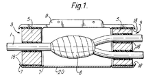
- Figure 1 shows a splice 8 between cables 1 enclosed by a closure made according to the invention.
- the closure comprises a cover 20 in the form of a dimensionally heat-stable wraparound sleeve, and sealing means 3.
- the sealing means 3 comprises a sealing material 18 and a substantially rigid portion 5.
- the sleeve may be shaped, for example as shown at 7, to aid retention of the sealing means 3.
- the sleeve 20 is shown in longitudinal section, the top part 9 terminating in a closure member at each of two opposing longitudinal edges of the sleeve. These edges (one of which is shown) may be held together by a channel or grabber 24 (see figure 8).
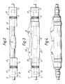
- Figure 2 shows in combination two wraparound heat-recoverable sleeves 2 pre-installed by partial recovery onto hinged aluminium inserts 4 having tapered fingers.
- the partially recovered combination is wrapped around cables entering the splice area 8.
- Closure channels 10 are positioned on rails 12 on the wrapped sleeve 2 to close the sleeve.
- End regions 14 of the sleeve are bare of both rail and channel so that they provide a plain cylindrical surface.
- a metal bond bar 16 connects the two aluminium liners over the splice region.
- Strips of sealing material 18 according to the invention are wrapped around the substrates within the sleeves 2.
- Figure 3 shows a central wraparound heat-stable sleeve 20 positioned to overlap the rail and channel-bare portions 14 of the heat-recoverable sleeves.
- the sleeve 20 may have the shape as shown or it may be shaped at its ends to correspond to the shape shown in Figure 4.
- the central wraparound sleeve 20 has upstanding rails 22 which are held together by a securing means in the form of a metal grabber 24. The grabber 24 also engages the ends of channels 10 on the heat-recoverable sleeves 2.
- Sealing strips of silicone rubber (shown dotted) or of a sealing material according to the invention extend around the circumference of the overlap region between the heat-recoverable sleeves 2 and the heat-stable sleeve 20, and beneath the rails 22 of the heat-stable sleeve 20.
- the heat-stable sleeve 20 is sealed closed and to the heat-recoverable sleeves 2.
- the heat-recoverable sleeves 2 are heated to shrink them into engagement or contact with the underlying cables. Where two or more cables enter the splice region 8 a branch-off clip (not shown) may be used between them.
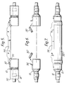
- FIG. 5 A second embodiment according to the invention is shown in Figures 5 - 7.
- rails 30 on the sleeve extend along the whole length of the heat recoverable sleeves 2. Only the channels 10 end short of one end.
- a channel member 32 acts as a temporary channel which together with channel 10 holds the whole length of a sleeve 2 closed during its recovery.
- a grabber 24 secures the channels 10 and insert channel members 32 together.
- a retention clip 34 secures the temporary channel member 32 to the tapered finger inserts 4, for alignment of the substrate.
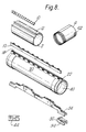
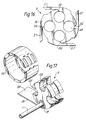
- FIG 8 shows in perspective the component parts of the embodiments of Figures 2 - 7 with like reference numerals indicating like parts.
- the additional features which can be seen in these drawings are the circumferential sealing strip cavities 40 in the heat-stable sleeve 20 and the aperture 42 in the tapered finger insert 4 for engaging the retention clip 34 of the temporary channel closure insert 32, and a branch-off clip 44 that can be positioned on an end of a sleeve 2 to form a plurality of conduits for branching cables.
- the clip preferably has a non-linear gap between its legs to aid retention of the clip before shrinkage of the sleeve.
- the sleeve 20 has a special closure 22, between which is positioned sealing material 18, and which may be locked closed by closure 10.
- FIG 9 shows a sealing means 3 that may be used, for example, in the enclosure of Figure 1.
- Sealing means 3 comprises a sealing material 18 and substantially rigid parts 5a, 5b and 5c.
- the parts 5a, 5b and 5c may be held together by holding means such as screws 46 that preferably have sharp points 47 in order easily to penetrate the sealing material 18.
- the sealing material 18 may be provided attached to one or more of parts 5a, 5b and 5c or may be applied first to the cables or other substrates to be sealed.
- the parts 5a, 5b and 5c together define holes 48 through which substrates to be sealed will pass. Since the parts are separable, the sealing means can be installed around substrates without access to a free end thereof.
- the outer surfaces of the means 3 may be provided with means for aiding retention of an external layer of sealing material (not shown) and such means for retaining may comprise a circumferentially-extending recess 50. Similar recesses 51 may be provided on the internal surfaces. Guide pins 49 may be provided to help align the parts 5a, 5b and 5c.
- the sealing material comprises the sealing material of the invention.
- the cable diameter may be as little as, for example, 40% of the size of the hole, although we prefer 50%, more preferably 70%, especially 75%, particularly 80%. The larger differences in size can be accommodated with the sealing materials of the invention to produce a good seal for the product life-time generally expected of such cable accessories.
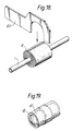
- Figure 10 shows a sealing means 3 analogous to that of Figure 9, but for a single substrate.
- Figures 11 and 12 show a way of installing a strip of sealing material 18 around a rigid portion 5 of a sealing means 3.
- Figure 13 shows a way in which sealing material 18 may be pre-affixed to at least one of the parts 5a, 5b and 5c. It may be supplied thus pre-affixed (produced for example by injection moulding) or a preshaped sealing material part may be installed thus in the field. A region 52 of sealing material may be missing to ease insertion of the screw 46.
- the parts 5a, 5b and 5c may be shaped to prevent or reduce shearing of the sealing material on assembly, for example by bevelling as shown at 53.
- the sealing material may be provided with a web or other part 54 that may be wrapped or otherwise positioned around the substrate when positioned in the holes 48.
- Figure 14 shows an article 54 that may be used to aid installation of the sealing means shown in Figure 13.
- the article 54 may comprise a card (or other sheet) having recesses 55 along an edge (or holes therethrough) which can be used to measure the cables or other substrates to be sealed.
- a position, A,B, or C is determined where one of a pair of recesses accepts the cable, but the other of the pair does not.
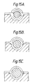
- Adjacent each pair may be provided a- drawing or other instructions showing how to deal with the web of sealing material for the appropriate size of cable. This is further illustrated in Figures 15a, 15b, 15c where the sealing material can be seen to be cut and wrapped in different ways.
- Figure 16 shows a sealing means 3 consisting substantially entirely of sealing material 18.
- the sealing material is split at position 56, for example, to allow cables to be laterally inserted into holes 48. Flaps 57 may be provided to aid formation of a sealed circumference.
- the sealing material of the invention is used.
- FIG 17 shows an alternative design of sealing means 3 in which a rigid part 5 has laterally open holes 48 into which cables 1 may be inserted.
- the cables may be sealed to the part 5 by a sealing material 18, preferably in the form of a sheet (or tape) wrap.
- a cage or other support 58 may be provided around the outside of the sealing means 3.
- a wrap 59 of sealing material may provide a seal between the part 5 and the cage 58.
- Figure 18 shows how an article 60 may be used to judge how much sealing material 18 is to be installed, by tape wrapping etc, around a cable 1.
- the article 60 like the article 54 may be supplied as part of a kit of parts comprising sealing means/sealing material and cover etc.
- Figure 19 shows a blank (61), preferably cylindrical, wrapped with sealing material for use in temporarily or permanently blocking a hole 48 in a sealing means 3, where the sealing means has more holes than cables to be sealed.
- Figures 20a and 20b show a device 62 that may be secured to a sealing means to provide an enclosure with mechanical strength for example axial pull strength, or with electrical earth continuity.
- Armour 63 or other strength member of cables 1 may be secured to a flange or other part of device 62 by securing means such as bolt 64.
- Preferably inner plates (see figure 22) are fixed to the cables, allowing outer plates to move to deform a sealing material between them. The arrangement could, however, be reversed.
- sealing means 3 comprises a deformable material 5, and optionally a further sealing material 18.
- Sealing material 18, where present may be, for example, a softer and/or more adhesive material than material 5.
- Means 65 is provided to contain and preferably also to deform material 5, and optionally also material 18.
- Means 65 preferably comprises a pair of plates through each of which passes one or more cables and around which bears the sleeve 20. The plates are therefore preferably substantially circular, depending on the shape of the sleeve. The plates are preferably moveable towards one another, preferably axially with respect to the cable or cables. This movement may be brought about by means 66, preferably a bolt along which a nut 67 may be screwed.
- sealing material axially which results in its being deformed radially outwardly against the sleeve and/or inwardly against the cable or cables.
- This deformation may of course be transmitted via sealing material 18.
- resilient means 68 such as a coil or other spring may be provided (optionally on one or more bolts 66) to maintain the sealing material 5 and/or 18 under compression.
- the means 65 may be of "wrap around” design such that it can be installed around an intermediate portion of a cable, and may for example comprise split plates (parts of which may be hinged or otherwise joined together) where the split passes through a hole for the cables.
- FIG 22 A further feature is shown in figure 22, which may be combined with any of those in figure 21 or with any items in this specification.
- Figure 22 shows how two materials 69 and 70 may be combined.
- Material 69 may be rigid but it is preferably a deformable sealing material, allowing the plates 65 to be brought together as described above.
- Material 69 preferably contains and/or restrains another, generally softer, sealing material 70. In this way, an environmental seal can be made by material 70. The volume of material 70 that is required is therefore reduced, and due to the small space it occupies, the effect of its creep is reduced.
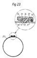
- Figure 23 illustrates in transverse cross-section a wrap-around sleeve or central portion 20 of a splice case, having protuberances, often known as rails, 72 which can be held together by a channel 73, thereby maintaining the sleeve in the closed or wrapped-around configuration.
- the channel may interlock one of the rails by a hinge-type of mechanism (the left-hand rail as drawn) and be secured to at least a part of the other rail by means such as a rod 74 that traps the channel. In this way the channel may be positioned in place radially with respect to the sleeve, even through the rod 74 may require longitudinal sliding in place.
- This channel 73 may have a reservoir 75 that carries a sealing material 76, such as a gel.
- a sealing material 76 such as a gel.
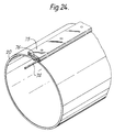
- FIG. 24 A perspective view of such a sleeve is shown in figure 24.
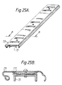
- the channel 73 is shown in figures 25A and 25B. Here it has resilient means such as a spring 77 to cause the reservoir 75 to force a sealing material in the desired direction. Alternatively, the resilient means may be separate from the channel thus allowing easy installation of the channel. Once the channel is properly installed the resilient means can be applied to bias a sealing material as desired, for example via reservoir 75.
- resilient means may comprise springs that are inserted through slots in the top of channel 73, and optionally then slid to apply a wedging action between reservoir 73 and channel 75.
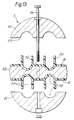
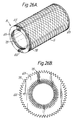
- Figures 26A and 26B show an embodiment of the sealing means 3 of for example Figure 21.
- the means has end plates 65 having tapering fingers 78 on their external surfaces (that which seals to the outer sleeve 20) and/or on their internal surfaces (that or those which seal to a cable or cables passing through). These tapering fingers 78 give the plates a crowned appearance and can provide some variation in diameter to suit sleeves and/or cables of different sizes.
- Means 66 may be provided to draw together plates 65 at opposite ends of the sealing means 3 thereby deforming a sealing material 5 positioned between them. The crowns thus serve as a variable size retaining means for the sealing material.
- Figures 27A and 27B show transverse cross-sections through edge portions 71 of a sleeve 20 for example as illustrated in figures 21 and 23.
- the section of figure 27A is taken at a position of the sleeve that surrounds a sealing means 3, whereas the section of figure 27B applies at positions between the sealing members (and may also overlap each sealing member).
- the difference between the two sections is that the section of figure 27A has a hole 79 through which a sealing material 76 (see figure 23) may pass. This is desirable so that the sealing material of the longitudinal seal of the sleeve 20 can touch and seal to the circumferential seal between the cables and sleeve provided by the sealing means 3.
- the hole 79 preferably tapers towards the outside of the sleeve, an angle of taper of say 120° or 135° being preferred but angles from 30 - 160°, especially 60 - 140° will in general be suitable.
- This hole is preferably about 1.5 - 10 mm, particularly 2 - 6 mm at its narrowest, and it preferably extends 1 - 4 cms, particularly 1.5 - 2.5 cms along the length of the sleeve.
- the two edges of figure 27A or B may interlock in tongue-and-groove fashion.
- an overlying flange (as shown in figure 27B) may have a downward facing projection that snaps into a recess in an underlying flange.
- Figure 28A illustrates in detail a portion of an end sealing means 3 from figure 28B which illustrates a splice case.
- Figure 28A shows a soft gel (or other sealing material) 70 located by a hard gel (or other sealing material) 69.
- Wrap-around end plates 65 (a substantially rigid portion as referred to herein) having crowns 78 are located either side of the hard gel 69.
- the crowns help to retain the gel and optionally to direct it in the desired way as it is being deformed by the end plates as they move together, in particular to restrain the gel against axial extension.
- the end plates 65 may be of the type illustrated in figure 26.
- a spring 68, tensioned by means 66 comprising for example a bolt and a nut 67 acting through resilient means such as a coil spring 68.
- a resilient bias can be put on the sealing material 70 that can accommodate any creep during service life of the splice case and maintain a seal between cables 4 and sleeve 20.
- a ratchet mechanism may be provided, releasable by for example slightly turning "nut” 67 with respect to means 66, and tightened for example levering the "nut” along means 66.
- the spring may be partly housed within the sealing means 3, and a part protruding may then act to indicate the extent to which it has been tensioned.
- the spring may be positioned within a cylindrical or other housing 80 which may help to locate it and facilitate viewing to determine tensioning, by for example providing markings on the housing 80, or by arranging for proper tensioning to occur when the housing 80 is flush with the flange 65.
- the spring will not begin to be compressed until the plates have been brought together sufficiently to begin to apply a compressive force on the sealing material; in this way the extent of compression of the spring will be an indication of the force on the sealing material.
- Plugs for example of sealing material, may be provided in unused outlets. Such plugs may have a diabolo shape to correspond to the shape of the crowns 78 (one of which is shown and another of which may be provided on an inner end plate complementing out end plate 65, as shown in figure 22).
- the end plates 65 of figure 28A etc may comprise the following design.
- An end plate may comprise an inner part (which may comprise one or more sub-parts, and through which means 66 may run or to which it may be attached) and one or more (preferably two) outer parts that in use at least lie substantially coaxially around the inner part.
- the or each outlet for the cables preferably lies partly in the inner part and partly within an outer part and is thus formed into an outlet of closed cross-section when the inner and outer parts are brought together. In this way, the end parts may be of "wrap-around" design.
- the inner part may be of generally star or cruciform-shape, where intersections of the arms of the cross have a semi-circular concave surface, preferably carrying half of crown 78.
- the outer part has corresponding semi-circular concave surfaces also carrying half of crowns 78.
- Two outer parts are preferably provided, preferably substantially semi-cylindrical. Each such part preferably pivots about a line adjacent its longitudinal edge, the two being pivotally connected to mutually adjacent positions of the inner part, preferably adjacent the ends of one of the arms of the cross when the inner part is of cruciform shape.
- the two outer parts may then be closed, clam-shell like, around the inner part, and optionally locked closed.
- Two ends plates of that design are preferably provided with a gel or other sealing material therebetween.
- the sealing material may be shaped similarly to the inner and outer parts, and parts of the sealing material may be bonded or otherwise fixed to corresponding parts of the end plates. The end plates may then be drawn together to deform the sealing material as required.
Landscapes
- Chemical & Material Sciences (AREA)
- Dispersion Chemistry (AREA)
- Chemical Kinetics & Catalysis (AREA)
- Medicinal Chemistry (AREA)
- Polymers & Plastics (AREA)
- Organic Chemistry (AREA)
- Health & Medical Sciences (AREA)
- Cable Accessories (AREA)
- Sealing Material Composition (AREA)
- Compositions Of Macromolecular Compounds (AREA)
- Sealing Devices (AREA)
- Insulating Bodies (AREA)
- Wrappers (AREA)
- Installation Of Indoor Wiring (AREA)
- Buffer Packaging (AREA)
Abstract
Claims (32)
- Procédé pour protéger du milieu ambiant un substrat allongé avec un élément de recouvrement et un moyen d'obturation étanche comportant une matière d'obturation étanche ayant un allongement à 23°C d'au moins 100 %, qui comprend l'opération consistant à positionner le moyen d'obturation étanche autour d'une partie du substrat et l'opération consistant à entourer le substrat avec l'élément de recouvrement afin que le moyen d'obturation étanche forme un joint étanche entre l'élément de recouvrement et le substrat, caractérisé en ce que la composition de la matière d'obturation étanche est choisie de façon à donner une déformation permanente par sollicitation de compression, telle que déterminée par la norme ASTM 395-A5, à 70°C, de moins de 30 %.
- Procédé selon la revendication 1, dans lequel l'élément de recouvrement comporte un manchon enroulé dimensionnellement stable à la chaleur.
- Procédé selon l'une quelconque des revendications précédentes, dans lequel l'élément de recouvrement est d'une dimension intérieure, en section transversale, sensiblement fixe et la matière d'obturation étanche est positionnée autour du substrat pour élever la dimension en section transversale du substrat sensiblement à celle de l'élément de recouvrement.
- Procédé selon l'une quelconque des revendications précédentes, dans lequel un moyen d'obturation étanche est positionné autour du substrat en deux parties espacées de celui-ci, et l'élément de recouvrement est positionné de façon à former un pont entre les deux moyens d'obturation étanche.
- Procédé selon l'une quelconque des revendications précédentes, dans lequel le substrat comprend deux ou plus de deux câbles épissés.
- Procédé selon l'une quelconque des revendications précédentes, dans lequel le moyen d'obturation étanche comprend la matière d'obturation étanche et une partie sensiblement rigide traversée d'au moins un trou à travers lequel le substrat peut passer.
- Procédé selon la revendication 6, dans lequel le trou est délimité circonférentiellement en totalité par ladite partie sensiblement rigide.
- Procédé selon la revendication 7, dans lequel ladite partie sensiblement rigide comprend deux ou plus de deux portions, pouvant être séparées suivant une ligne qui divise le trou.
- Procédé selon l'une quelconque des revendications précédentes, dans lequel la matière d'obturation étanche est prévue en étant fixée au préalable à une partie sensiblement rigide du moyen d'obturation étanche.
- Procédé selon la revendication 9, dans lequel la matière d'obturation étanche est fixée à la partie sensiblement rigide par moulage par injection.
- Procédé selon l'une quelconque des revendications précédentes, qui consiste en outre à soumettre la matière d'obturation étanche à une force de compression.
- Procédé selon l'une quelconque des revendications précédentes, dans lequel la matière d'obturation étanche comprend un gel (lequel terme englobe ici un gelloïde).
- Procédé selon l'une quelconque des revendications précédentes, dans lequel la matière d'obturation étanche est renforcée ou retenue contre une extension qui, lorsque la matière est installée, est axiale par rapport au substrat.
- Procédé selon l'une quelconque des revendications précédentes, dans lequel la matière d'obturation étanche comprend un copolymère séquencé styrène-éthylènebutylène-styrène dilué avec une huile minérale.
- Procédé selon la revendication 14, dans lequel le copolymère séquencé présente un poids moléculaire maximal de 257 000 à 267 000.
- Procédé selon la revendication 14 ou 15, dans lequel la matière d'obturation étanche comprend additionnellement une résine oxyde de polyphénylène/polyamide.
- Procédé selon l'une quelconque des revendications précédentes, dans lequel la matière d'obturation étanche présente une déformation permanente par sollicitation de compression à 70°C de moins de 15 %.
- Procédé selon l'une quelconque des revendications précédentes, dans lequel la matière d'obturation étanche présente un allongement d'au moins 500 %.
- Procédé selon la revendication 18, dans lequel la matière d'obturation étanche a un module de mémoire dynamique à 23°C et 1 Hz de moins de 10⁵ Pa (10⁶ dynes/cm²).
- Procédé selon la revendication 19, dans lequel la matière d'obturation étanche a un module de mémoire dynamique de moins de 3,6 x 10⁴ Pa (3,6 x 10⁵ dynes/cm²).
- Moyen d'obturation étanche pour former un joint étanche entre un élément de recouvrement et un substrat allongé, le moyen d'obturation étanche étant défini par l'une quelconque des revendications précédentes.
- Ensemble pour protéger du milieu ambiant un substrat allongé qui comporte un élément de recouvrement et un moyen d'obturation étanche tel que défini dans l'une quelconque des revendications précédentes.
- Substrat allongé protégé du milieu ambiant par un ensemble selon la revendication 22.
- Matière d'obturation étanche ayant un allongement à 23°C d'au moins 100 % et une déformation permanente par sollicitation de compression telle que déterminée par la norme ASTM 395-A5, à 70°C, de moins de 30 % et un module de mémoire dynamique à 23°C et à 1 Hz de moins de 10⁵ Pa (10⁶ dynes/cm²).
- Matière d'obturation étanche selon la revendication 24, ayant une déformation permanente par sollicitation de compression à 70°C de moins de 15 %.
- Matière d'obturation étanche selon la revendication 24 ou 25, ayant un allongement d'au moins 500 %.
- Matière d'obturation étanche selon l'une quelconque des revendications 24-26, comprenant un gel.
- Matière d'obturation étanche selon l'une quelconque des revendications 24-27, comprenant un copolymère séquencé styrène-éthylène-butylène-styrène dilué avec une huile minérale.
- Matière d'obturation étanche selon l'une quelconque des revendications 24-28, qui comprend un copolymère séquencé dilué avec une huile, ainsi qu'une résine du type oxyde de polyphénylène/polyamide
- Matière d'obturation étanche selon la revendication 28 ou 29, qui comprend additionnellement un agent de compatibilité.
- Matière d'obturation étanche ayant les propriétés suivantes :
Point de ramollissement initial 160-180°C
Module de mémoire dynamique 1,5 x 10⁴ - 2 x 10⁴ Pa (1,5 x 10⁵ - 2 x 10⁵ dynes/cm²) (23°C, 1 Hz)
Amortissement mécanique dynamique 0,15-0,4 (23°C, 1 Hz)
Résistance à la traction (23°C) inférieure à 1,0 MPa
Allongement (23°C) supérieur à 1000 %
Déformation permanente par sollicitation de compression (70°C) inférieure à 10 % (mesurée par la norme ASTM 395-A5) Déformation permanente par sollicitation de compression (90°C) inférieure à 20 %. - Matière d'obturation étanche selon la revendication 31, qui comprend (a) un copolymère séquencé contenant des séquences relativement dures et des séquences relativement élastomériques ; (b) une matière additionnelle à polymère ou copolymère ayant une compatibilité au moins partielle avec les séquences dures du copolymère séquencé et une température de ramollissement ou de transition vitreuse supérieure à celle des séquences dures du copolymère séquencé ; et (c) un liquide de dilution qui dilue et ramollit les séquences élastomériques dudit copolymère séquencé.
Applications Claiming Priority (7)
| Application Number | Priority Date | Filing Date | Title |
|---|---|---|---|
| GB888826250A GB8826250D0 (en) | 1988-11-09 | 1988-11-09 | Closure assembly |
| GB8826250 | 1988-11-09 | ||
| GB898902795A GB8902795D0 (en) | 1989-02-08 | 1989-02-08 | Gels |
| GB8902795 | 1989-02-08 | ||
| GB898912375A GB8912375D0 (en) | 1989-05-30 | 1989-05-30 | Closure assembly |
| GB8912375 | 1989-05-30 | ||
| PCT/GB1989/001335 WO1990005401A1 (fr) | 1988-11-09 | 1989-11-09 | Ensemble de boitier |
Publications (2)
| Publication Number | Publication Date |
|---|---|
| EP0442941A1 EP0442941A1 (fr) | 1991-08-28 |
| EP0442941B1 true EP0442941B1 (fr) | 1995-01-25 |
Family
ID=27264164
Family Applications (1)
| Application Number | Title | Priority Date | Filing Date |
|---|---|---|---|
| EP89912862A Expired - Lifetime EP0442941B1 (fr) | 1988-11-09 | 1989-11-09 | Materiau d'etancheite, boitier utilisant ce materiau et realisation du boitier |
Country Status (13)
| Country | Link |
|---|---|
| EP (1) | EP0442941B1 (fr) |
| JP (1) | JP2858419B2 (fr) |
| KR (1) | KR100224527B1 (fr) |
| AR (1) | AR247957A1 (fr) |
| AT (1) | ATE117853T1 (fr) |
| AU (2) | AU648497B2 (fr) |
| BR (1) | BR8907763A (fr) |
| CA (1) | CA2002628A1 (fr) |
| DE (1) | DE68920883T2 (fr) |
| DK (1) | DK168841B1 (fr) |
| NO (1) | NO301200B1 (fr) |
| TR (1) | TR24079A (fr) |
| WO (1) | WO1990005401A1 (fr) |
Cited By (25)
| Publication number | Priority date | Publication date | Assignee | Title |
|---|---|---|---|---|
| US8207445B2 (en) | 2006-04-11 | 2012-06-26 | Ccs Technology, Inc. | Sealing body for a cable sleeve |
| EP2523287A1 (fr) | 2011-05-10 | 2012-11-14 | Tyco Electronics Raychem BVBA | Dispositif d'étanchéité de câble doté d'un mur de confinement étanche doté de portions mobiles permettant d'accommoder les câbles de différentes tailles |
| EP2523286A1 (fr) | 2011-05-10 | 2012-11-14 | Tyco Electronics Raychem BVBA | Dispositif de scellage de câble disposant d'un confinement hermétique autonome |
| EP2523288A1 (fr) | 2011-05-10 | 2012-11-14 | Tyco Electronics Raychem BVBA | Dispositif de scellage de câble actionné par levier à came |
| US8604360B2 (en) | 2006-04-11 | 2013-12-10 | Ccs Technology, Inc. | Sealing body for a cable sleeve |
| WO2014005919A2 (fr) | 2012-07-02 | 2014-01-09 | Tyco Electronics Raychem Bvba | Actionneur d'étanchéité à indicateur de niveau d'actionnement |
| WO2014005918A2 (fr) | 2012-07-02 | 2014-01-09 | Tyco Electronics Raychem Bvba | Réducteur de taille d'orifice pour câbles |
| WO2014005917A2 (fr) | 2012-07-02 | 2014-01-09 | Tyco Electronics Raychem Bvba | Enceinte réouvrable |
| WO2014005916A2 (fr) | 2012-07-02 | 2014-01-09 | Tyco Electronics Raychem Bvba | Unité d'étanchéification de câble comportant plusieurs modules d'étanchéité |
| WO2014128138A2 (fr) | 2013-02-19 | 2014-08-28 | Tyco Electronics Raychem Bvba | Boîtier ré-entrable, et configuration pour son montage |
| WO2015097141A1 (fr) * | 2013-12-23 | 2015-07-02 | Tyco Electronics Raychem Bvba | Unité d'étanchéité de câble à actionneur hermétiquement scellé |
| WO2017046063A1 (fr) | 2015-09-14 | 2017-03-23 | CommScope Connectivity Belgium BVBA | Agencements de blocs d'étanchéité pour enceintes |
| WO2017046064A1 (fr) | 2015-09-14 | 2017-03-23 | CommScope Connectivity Belgium BVBA | Agencements de bloc d'étanchéité pour enceintes |
| WO2017046185A3 (fr) * | 2015-09-14 | 2017-04-27 | CommScope Connectivity Belgium BVBA | Boîtier étanche réouvrable |
| US9864157B2 (en) | 2011-02-16 | 2018-01-09 | Commscope Technologies Llc | Fiber optic closure |
| WO2018048910A2 (fr) | 2016-09-07 | 2018-03-15 | Commscope Technologies Llc | Gels d'étanchéité de câble anisotrope; et procédés pour la fabrication de gels d'étanchéité de câble |
| WO2018158362A1 (fr) | 2017-03-01 | 2018-09-07 | CommScope Connectivity Belgium BVBA | Unité d'étanchéité de câble avec des modules d'étanchéité de câble |
| WO2018234579A1 (fr) | 2017-06-23 | 2018-12-27 | CommScope Connectivity Belgium BVBA | Enceinte de télécommunications et composants associés |
| US10298003B2 (en) | 2009-12-03 | 2019-05-21 | CommScope Connectivity Belgium BVBA | Gel sealing device |
| WO2019241230A1 (fr) | 2018-06-12 | 2019-12-19 | Commscope Technologies Llc | Procédé et système d'installation de câble |
| US10935135B2 (en) | 2016-04-01 | 2021-03-02 | CommScope Connectivity Belgium BVBA | Multi-component seal and enclosure |
| WO2021152145A1 (fr) | 2020-01-31 | 2021-08-05 | CommScope Connectivity Belgium BV | Unité d'étanchéification de câble avec plusieurs configurations |
| US11215778B2 (en) | 2018-03-09 | 2022-01-04 | Commscope Technologies Llc | Cable seals with reinforcements |
| WO2023028158A1 (fr) * | 2021-08-27 | 2023-03-02 | Commscope Technologies Llc | Presse-étoupe de câble |
| US12032218B2 (en) | 2018-10-26 | 2024-07-09 | Commscope Technologies Llc | Cable sealing module |
Families Citing this family (60)
| Publication number | Priority date | Publication date | Assignee | Title |
|---|---|---|---|---|
| DE4029082A1 (de) * | 1990-09-13 | 1992-03-19 | Rose Walter Gmbh & Co Kg | Vorrichtung zum abdichten von in eine kabelmuffe einlaufenden kabeln |
| GB9112181D0 (en) * | 1991-06-06 | 1991-07-24 | Raychem Sa Nv | Cable sealing |
| JPH06507778A (ja) * | 1991-06-06 | 1994-09-01 | エヌ・ヴェ・レイケム・ソシエテ・アノニム | ケーブル封止 |
| US5588856A (en) * | 1991-09-18 | 1996-12-31 | Raychem Corporation | Sealing member and methods of sealing |
| US5245133A (en) * | 1991-10-15 | 1993-09-14 | Thomas & Betts Corporation | Moisture-resistant cable splice and sealing structure thereof |
| US5589666A (en) * | 1991-10-15 | 1996-12-31 | Thomas & Betts Corporation | Enclosure for sealing a splice of electrical cables |
| US5251373A (en) * | 1991-10-15 | 1993-10-12 | Thomas & Betts Corporation | Method for protection of cable splices |
| US5258578A (en) * | 1992-02-18 | 1993-11-02 | Minnesota Mining And Manufacturing Company | Closure end seal |
| GB9203943D0 (en) * | 1992-02-25 | 1992-04-08 | Raychem Sa Nv | Cable seal |
| US5618882A (en) * | 1992-05-13 | 1997-04-08 | Raychem Limited | Gels containing SEPS block polymers |
| GB9212624D0 (en) * | 1992-06-15 | 1992-07-29 | Raychem Sa Nv | Cable sealing device |
| US5288946A (en) * | 1992-06-18 | 1994-02-22 | Minnesota Mining And Manufacturing Company | Strain relief device and closure |
| US5426715A (en) * | 1993-07-23 | 1995-06-20 | Raychem Corporation | Oval port seal and method used for an optical fiber cable closure |
| DE4333067C1 (de) * | 1993-09-29 | 1995-03-09 | Rose Walter Gmbh & Co Kg | Vorrichtung zur Bildung eines Muffeneinganges, insbesondere für Glasfaserkabel |
| MY112885A (en) * | 1993-12-01 | 2001-10-31 | N V Raychem S A | Sealing device. |
| DE4342000C2 (de) * | 1993-12-09 | 1995-10-19 | Stewing Kunststoff | Muffengehäuse zum Verbinden, Abzweigen und Aufteilen von Bündeladern und ihrer Glasfasern von Glasfaserkabeln |
| US5446823A (en) * | 1994-01-26 | 1995-08-29 | Raychem Corporation | Aerial, pedestal, below grade, or buried optical fiber closure |
| GB9404396D0 (en) * | 1994-03-07 | 1994-04-20 | Raychem Sa Nv | Sealing arrangement |
| US5529508A (en) * | 1994-04-01 | 1996-06-25 | Raychem Corporation | Sealing member |
| FR2723271B1 (fr) * | 1994-07-29 | 1998-01-30 | Pirelli Cables Sa | Accessoire de raccordement de cables d'energie basse tension |
| AR001330A1 (es) * | 1994-12-12 | 1997-10-22 | Raychem Sa Nv | Un miembro sellador. |
| US5696351A (en) * | 1995-03-10 | 1997-12-09 | Ericsson Raynet | Cable retention and sealing device |
| GB9513400D0 (en) * | 1995-06-30 | 1995-09-06 | Raychem Sa Nv | Apparatus for enclosing part of an elongate object |
| GB9611371D0 (en) | 1996-05-31 | 1996-08-07 | Raychem Sa Nv | Sealed article |
| US5792989A (en) * | 1996-11-12 | 1998-08-11 | Minnesota Mining And Manufacturing Company | Wrap type cable closure end seal |
| AU2326197A (en) * | 1996-11-12 | 1998-06-03 | Minnesota Mining And Manufacturing Company | Clamp type cable closure end seal |
| EP1074078A1 (fr) | 1998-04-28 | 2001-02-07 | Tyco Electronics Raychem NV | Boitier |
| US6430020B1 (en) | 1998-09-21 | 2002-08-06 | Tyco Electronics Corporation | Overvoltage protection device including wafer of varistor material |
| US6038119A (en) * | 1998-09-21 | 2000-03-14 | Atkins; Ian Paul | Overvoltage protection device including wafer of varistor material |
| TR200101220T2 (tr) | 1998-11-06 | 2001-08-21 | Tyco Electronics Raychem N.V. | Kaplo kapağı |
| FR2820555B1 (fr) * | 2001-02-06 | 2003-04-11 | 3M Innovative Properties Co | Passage de cable etanche et modulaire a positionnement de cable facilite et manchon equipe d'un tel passage |
| FR2820556A1 (fr) * | 2001-02-06 | 2002-08-09 | 3M Innovative Properties Co | Passage de cable etanche a moyens de compression simplifies et manchon equipe d'un tel passage |
| US6854996B2 (en) | 2002-12-20 | 2005-02-15 | Tyco Electronics Corporation | Electrical connectors and methods for using the same |
| WO2004075359A1 (fr) | 2003-02-18 | 2004-09-02 | Homac Mfg. Company | Connecteur et botte isolante pour deconnecteurs de tailles differentes et procedes associes |
| US7141738B2 (en) | 2004-02-02 | 2006-11-28 | 3M Innovative Properties Company | Re-enterable splice enclosure |
| DE202005014677U1 (de) * | 2005-09-16 | 2005-11-17 | CCS Technology, Inc., Wilmington | Vorrichtung zur Abfangung von Kabeln |
| US7433169B2 (en) | 2005-12-15 | 2008-10-07 | Raycap Corporation | Overvoltage protection devices including wafer of varistor material |
| US7201596B1 (en) | 2006-01-06 | 2007-04-10 | Tyco Electronics Corporation | Electrical connector systems, plug systems and methods for using the same |
| US7736187B2 (en) | 2007-03-20 | 2010-06-15 | Tyco Electronics Corporation | Electrical connector assemblies and joint assemblies and methods for using the same |
| US7736165B2 (en) | 2007-07-16 | 2010-06-15 | Tyco Electronics Corporation | Electrical connector assemblies and methods for forming and using the same |
| ITMI20081082A1 (it) | 2008-06-16 | 2009-12-17 | Optotec Spa | Dispositivo per sigillare cavi attraverso contenitori per fibre ottiche e contenitore comprendente tale dispositivo |
| US8718434B2 (en) | 2008-07-01 | 2014-05-06 | Adc Telecommunications, Inc. | Cable enclosure with sealed cable entry port |
| US8415564B2 (en) * | 2009-11-04 | 2013-04-09 | Tyco Electronics Corporation | Wrap-around cable sleeve assemblies and methods for making and using the same |
| CN102221735B (zh) * | 2010-04-16 | 2013-07-17 | 泰科电子(上海)有限公司 | 光缆接头盒 |
| CN202094558U (zh) * | 2011-01-27 | 2011-12-28 | 中兴通讯股份有限公司 | 过线盒 |
| US9265629B2 (en) | 2011-04-01 | 2016-02-23 | The Ohio Willow Wood Company | Fabric covered polymeric prosthetic liner |
| AU2013265224B2 (en) * | 2012-05-25 | 2017-02-02 | CommScope Connectivity Belgium BVBA | Cable Seal Block Assemblies and Method of Using Thereof |
| US8743525B2 (en) | 2012-06-19 | 2014-06-03 | Raycap Intellectual Property, Ltd | Overvoltage protection devices including wafer of varistor material |
| DE202012013316U1 (de) | 2012-12-18 | 2016-03-11 | Reichle & De-Massari Ag | Kabelkontaktierungswitterungsschutz |
| US9906017B2 (en) | 2014-06-03 | 2018-02-27 | Ripd Research And Ip Development Ltd. | Modular overvoltage protection units |
| WO2016185049A1 (fr) | 2015-05-21 | 2016-11-24 | CommScope Connectivity Belgium BVBA | Assemblages de trous de câble scellables pour enceinte de télécommunications |
| US10319545B2 (en) | 2016-11-30 | 2019-06-11 | Iskra Za{hacek over (s)}{hacek over (c)}ite d.o.o. | Surge protective device modules and DIN rail device systems including same |
| US10707678B2 (en) | 2016-12-23 | 2020-07-07 | Ripd Research And Ip Development Ltd. | Overvoltage protection device including multiple varistor wafers |
| US10447026B2 (en) | 2016-12-23 | 2019-10-15 | Ripd Ip Development Ltd | Devices for active overvoltage protection |
| US10340110B2 (en) | 2017-05-12 | 2019-07-02 | Raycap IP Development Ltd | Surge protective device modules including integral thermal disconnect mechanisms and methods including same |
| US10685767B2 (en) | 2017-09-14 | 2020-06-16 | Raycap IP Development Ltd | Surge protective device modules and systems including same |
| US11223200B2 (en) | 2018-07-26 | 2022-01-11 | Ripd Ip Development Ltd | Surge protective devices, circuits, modules and systems including same |
| US11862967B2 (en) | 2021-09-13 | 2024-01-02 | Raycap, S.A. | Surge protective device assembly modules |
| US11723145B2 (en) | 2021-09-20 | 2023-08-08 | Raycap IP Development Ltd | PCB-mountable surge protective device modules and SPD circuit systems and methods including same |
| US11990745B2 (en) | 2022-01-12 | 2024-05-21 | Raycap IP Development Ltd | Methods and systems for remote monitoring of surge protective devices |
Family Cites Families (4)
| Publication number | Priority date | Publication date | Assignee | Title |
|---|---|---|---|---|
| EP0034042B1 (fr) * | 1980-02-08 | 1985-01-23 | N.V. Raychem S.A. | Assemblage d'enveloppe rétractable |
| GB2135139B (en) * | 1983-02-14 | 1986-04-09 | Raychem Sa Nv | Heat recoverable article |
| JPH0353561Y2 (fr) * | 1985-09-27 | 1991-11-22 | ||
| GB8617559D0 (en) * | 1986-07-18 | 1986-08-28 | Raychem Ltd | Gels |
-
1989
- 1989-11-08 AR AR89315402A patent/AR247957A1/es active
- 1989-11-08 TR TR89/0873A patent/TR24079A/xx unknown
- 1989-11-09 BR BR898907763A patent/BR8907763A/pt not_active IP Right Cessation
- 1989-11-09 JP JP2500575A patent/JP2858419B2/ja not_active Expired - Lifetime
- 1989-11-09 AU AU45293/89A patent/AU648497B2/en not_active Ceased
- 1989-11-09 CA CA002002628A patent/CA2002628A1/fr not_active Abandoned
- 1989-11-09 EP EP89912862A patent/EP0442941B1/fr not_active Expired - Lifetime
- 1989-11-09 AT AT89912862T patent/ATE117853T1/de not_active IP Right Cessation
- 1989-11-09 DE DE68920883T patent/DE68920883T2/de not_active Expired - Lifetime
- 1989-11-09 KR KR1019900701452A patent/KR100224527B1/ko not_active IP Right Cessation
- 1989-11-09 WO PCT/GB1989/001335 patent/WO1990005401A1/fr active IP Right Grant
-
1991
- 1991-05-08 DK DK086091A patent/DK168841B1/da not_active IP Right Cessation
- 1991-05-08 NO NO911796A patent/NO301200B1/no not_active IP Right Cessation
-
1994
- 1994-07-14 AU AU67584/94A patent/AU6758494A/en not_active Abandoned
Cited By (47)
| Publication number | Priority date | Publication date | Assignee | Title |
|---|---|---|---|---|
| US8604360B2 (en) | 2006-04-11 | 2013-12-10 | Ccs Technology, Inc. | Sealing body for a cable sleeve |
| US8207445B2 (en) | 2006-04-11 | 2012-06-26 | Ccs Technology, Inc. | Sealing body for a cable sleeve |
| US10910810B2 (en) | 2009-12-03 | 2021-02-02 | CommScope Connectivity Belgium BVBA | Gel sealing device |
| US10298003B2 (en) | 2009-12-03 | 2019-05-21 | CommScope Connectivity Belgium BVBA | Gel sealing device |
| US9864157B2 (en) | 2011-02-16 | 2018-01-09 | Commscope Technologies Llc | Fiber optic closure |
| EP2523287A1 (fr) | 2011-05-10 | 2012-11-14 | Tyco Electronics Raychem BVBA | Dispositif d'étanchéité de câble doté d'un mur de confinement étanche doté de portions mobiles permettant d'accommoder les câbles de différentes tailles |
| EP2523286A1 (fr) | 2011-05-10 | 2012-11-14 | Tyco Electronics Raychem BVBA | Dispositif de scellage de câble disposant d'un confinement hermétique autonome |
| EP2523288A1 (fr) | 2011-05-10 | 2012-11-14 | Tyco Electronics Raychem BVBA | Dispositif de scellage de câble actionné par levier à came |
| WO2012152643A2 (fr) | 2011-05-10 | 2012-11-15 | Tyco Electronics Raychem Bvba | Dispositif d'étanchéité pour câble présentant un confinement de joint autonome |
| WO2012152789A2 (fr) | 2011-05-10 | 2012-11-15 | Tyco Electronics Raychem Bvba | Dispositif d'étanchéité de câble actionné par un levier à came |
| US10208859B2 (en) | 2011-05-10 | 2019-02-19 | CommScope Connectivity Belgium BVBA | Cam lever actuated cable sealing device |
| WO2014005919A2 (fr) | 2012-07-02 | 2014-01-09 | Tyco Electronics Raychem Bvba | Actionneur d'étanchéité à indicateur de niveau d'actionnement |
| EP3252897A1 (fr) | 2012-07-02 | 2017-12-06 | CommScope Connectivity Belgium BVBA | Enceinte réinsérable |
| WO2014005919A3 (fr) * | 2012-07-02 | 2014-04-03 | Tyco Electronics Raychem Bvba | Actionneur d'étanchéité à indicateur de niveau d'actionnement |
| EP3346565A1 (fr) | 2012-07-02 | 2018-07-11 | CommScope Connectivity Belgium BVBA | Actionneur de joint comportant un indicateur de niveau d'actionnement |
| EP2867963A2 (fr) * | 2012-07-02 | 2015-05-06 | Tyco Electronics Raychem BVBA | Pièce de réduction pour dispositif de traversée pour câbles |
| US10084302B2 (en) | 2012-07-02 | 2018-09-25 | CommScope Connectivity Belgium BVBA | Re-enterable enclosure |
| DE202013012190U1 (de) | 2012-07-02 | 2015-10-16 | Tyco Electronics Raychem Bvba | Kabelabdichtungseinheit mit mehreren Abdichtungsmodulen |
| DE202013012284U1 (de) | 2012-07-02 | 2016-01-18 | Tyco Electronics Raychem Bvba | Kabelabdichtungseinheit mit mehreren Abdichtungsmodulen |
| DE202013012385U1 (de) | 2012-07-02 | 2016-08-09 | CommScope Connectivity Belgium BVBA | Kabelabdichtungseinheit mit mehreren Abdichtungsmodulen |
| WO2014005918A3 (fr) * | 2012-07-02 | 2014-03-27 | Tyco Electronics Raychem Bvba | Réducteur de taille d'orifice pour câbles |
| WO2014005916A2 (fr) | 2012-07-02 | 2014-01-09 | Tyco Electronics Raychem Bvba | Unité d'étanchéification de câble comportant plusieurs modules d'étanchéité |
| WO2014005917A2 (fr) | 2012-07-02 | 2014-01-09 | Tyco Electronics Raychem Bvba | Enceinte réouvrable |
| RU2632929C2 (ru) * | 2012-07-02 | 2017-10-11 | Тайко Электроникс Райхем Бвба | Устройство концевой заделки кабеля с несколькими герметизирующими модулями |
| WO2014005916A3 (fr) * | 2012-07-02 | 2014-03-27 | Tyco Electronics Raychem Bvba | Unité d'étanchéification de câble comportant plusieurs modules d'étanchéité |
| WO2014005918A2 (fr) | 2012-07-02 | 2014-01-09 | Tyco Electronics Raychem Bvba | Réducteur de taille d'orifice pour câbles |
| WO2014128138A2 (fr) | 2013-02-19 | 2014-08-28 | Tyco Electronics Raychem Bvba | Boîtier ré-entrable, et configuration pour son montage |
| WO2015097141A1 (fr) * | 2013-12-23 | 2015-07-02 | Tyco Electronics Raychem Bvba | Unité d'étanchéité de câble à actionneur hermétiquement scellé |
| WO2017046185A3 (fr) * | 2015-09-14 | 2017-04-27 | CommScope Connectivity Belgium BVBA | Boîtier étanche réouvrable |
| WO2017046064A1 (fr) | 2015-09-14 | 2017-03-23 | CommScope Connectivity Belgium BVBA | Agencements de bloc d'étanchéité pour enceintes |
| US10476250B2 (en) | 2015-09-14 | 2019-11-12 | CommScope Connectivity Belgium BVBA | Sealing block arrangements for enclosures |
| WO2017046063A1 (fr) | 2015-09-14 | 2017-03-23 | CommScope Connectivity Belgium BVBA | Agencements de blocs d'étanchéité pour enceintes |
| US11287039B2 (en) | 2016-04-01 | 2022-03-29 | CommScope Connectivity Belgium BVBA | Multi-component seal and enclosure |
| US10935135B2 (en) | 2016-04-01 | 2021-03-02 | CommScope Connectivity Belgium BVBA | Multi-component seal and enclosure |
| EP3510606B1 (fr) * | 2016-09-07 | 2024-05-15 | Commscope Technologies LLC | Gels d'étanchéité de câble anisotrope |
| WO2018048910A2 (fr) | 2016-09-07 | 2018-03-15 | Commscope Technologies Llc | Gels d'étanchéité de câble anisotrope; et procédés pour la fabrication de gels d'étanchéité de câble |
| US11333839B2 (en) | 2016-09-07 | 2022-05-17 | Commscope Technologies Llc | Anisotropic cable sealing gels; and methods for fabricating cable sealing gels |
| US11002929B2 (en) | 2017-03-01 | 2021-05-11 | CommScope Connectivity Belgium BVBA | Cable sealing unit with cable sealing modules |
| WO2018158362A1 (fr) | 2017-03-01 | 2018-09-07 | CommScope Connectivity Belgium BVBA | Unité d'étanchéité de câble avec des modules d'étanchéité de câble |
| US12050355B2 (en) | 2017-03-01 | 2024-07-30 | CommScope Connectivity Belgium BVBA | Cable sealing unit with cable sealing modules |
| US11300745B2 (en) | 2017-06-23 | 2022-04-12 | CommScope Connectivity Belgium BVBA | Telecommunications enclosure and related components |
| WO2018234579A1 (fr) | 2017-06-23 | 2018-12-27 | CommScope Connectivity Belgium BVBA | Enceinte de télécommunications et composants associés |
| US11215778B2 (en) | 2018-03-09 | 2022-01-04 | Commscope Technologies Llc | Cable seals with reinforcements |
| WO2019241230A1 (fr) | 2018-06-12 | 2019-12-19 | Commscope Technologies Llc | Procédé et système d'installation de câble |
| US12032218B2 (en) | 2018-10-26 | 2024-07-09 | Commscope Technologies Llc | Cable sealing module |
| WO2021152145A1 (fr) | 2020-01-31 | 2021-08-05 | CommScope Connectivity Belgium BV | Unité d'étanchéification de câble avec plusieurs configurations |
| WO2023028158A1 (fr) * | 2021-08-27 | 2023-03-02 | Commscope Technologies Llc | Presse-étoupe de câble |
Also Published As
| Publication number | Publication date |
|---|---|
| JPH04502548A (ja) | 1992-05-07 |
| JP2858419B2 (ja) | 1999-02-17 |
| DK86091A (da) | 1991-06-19 |
| KR900702613A (ko) | 1990-12-07 |
| DK86091D0 (da) | 1991-05-08 |
| AU4529389A (en) | 1990-05-28 |
| DE68920883D1 (de) | 1995-03-09 |
| NO301200B1 (no) | 1997-09-22 |
| DE68920883T2 (de) | 1995-09-14 |
| AU648497B2 (en) | 1994-04-28 |
| NO911796L (no) | 1991-05-08 |
| TR24079A (tr) | 1991-03-01 |
| KR100224527B1 (ko) | 1999-10-15 |
| EP0442941A1 (fr) | 1991-08-28 |
| DK168841B1 (da) | 1994-06-20 |
| AU6758494A (en) | 1994-09-29 |
| WO1990005401A1 (fr) | 1990-05-17 |
| AR247957A1 (es) | 1995-04-28 |
| ATE117853T1 (de) | 1995-02-15 |
| BR8907763A (pt) | 1991-08-27 |
| CA2002628A1 (fr) | 1990-05-09 |
| NO911796D0 (no) | 1991-05-08 |
Similar Documents
| Publication | Publication Date | Title |
|---|---|---|
| EP0442941B1 (fr) | Materiau d'etancheite, boitier utilisant ce materiau et realisation du boitier | |
| US5313019A (en) | Closure assembly | |
| EP0426658B1 (fr) | Gels comprenant des copolymeres bloc | |
| JP3920340B2 (ja) | ゲルを充填したクロージャー | |
| US4942270A (en) | Cable sealing apparatus comprising heat resistant gel compositions | |
| AU666650B2 (en) | Cable sealing | |
| EP0780949B1 (fr) | Adaptateur de câble universel, jonction de câble utilisant l'adaptateur et procédé de réalisation de celle-ci | |
| HUT75472A (en) | Sealing arrangement and adapter, method for sealing one or more through-going fibre-form objects | |
| US20080135288A1 (en) | Cold shrink article and method of using cold shrink article | |
| AU663867B2 (en) | Environmental sealing | |
| EP0835546B1 (fr) | Etancheite de cable | |
| EP0442920A1 (fr) | Gels | |
| JPH10505997A (ja) | ケーブルスプライスクロージャ | |
| JP2002505706A (ja) | 低モジュラスエラストマー | |
| EP1207608B1 (fr) | Séparateurs de fils comprenant des réservoirs de matériau d'étanchéité et fermetures d'épissures de câbles utilisant tels séparateurs | |
| EP0541530B1 (fr) | Protection et etanchement | |
| US5710206A (en) | Gels comprising block copolymers | |
| JPH11507495A (ja) | 伸長体の一部を封鎖するための装置 | |
| US20060202434A1 (en) | Cable sealing and/or feedthrough device | |
| AU2002339118B2 (en) | Electrical stress control article | |
| RU2144724C1 (ru) | Затвор для кабельного сращивания | |
| WO1995015602A1 (fr) | Dispositif d'etancheite au milieu ambiant | |
| EP0900463A1 (fr) | Passe-fil en caoutchouc a scellage moule sur place | |
| MXPA98003473A (en) | Closure filled with | |
| NO303253B1 (no) | Kabeltetning |
Legal Events
| Date | Code | Title | Description |
|---|---|---|---|
| PUAI | Public reference made under article 153(3) epc to a published international application that has entered the european phase |
Free format text: ORIGINAL CODE: 0009012 |
|
| 17P | Request for examination filed |
Effective date: 19910417 |
|
| AK | Designated contracting states |
Kind code of ref document: A1 Designated state(s): AT BE CH DE FR GB IT LI NL SE |
|
| 17Q | First examination report despatched |
Effective date: 19930331 |
|
| GRAA | (expected) grant |
Free format text: ORIGINAL CODE: 0009210 |
|
| AK | Designated contracting states |
Kind code of ref document: B1 Designated state(s): AT BE CH DE FR GB IT LI NL SE |
|
| REF | Corresponds to: |
Ref document number: 117853 Country of ref document: AT Date of ref document: 19950215 Kind code of ref document: T |
|
| REF | Corresponds to: |
Ref document number: 68920883 Country of ref document: DE Date of ref document: 19950309 |
|
| ITF | It: translation for a ep patent filed | ||
| ET | Fr: translation filed | ||
| PLBE | No opposition filed within time limit |
Free format text: ORIGINAL CODE: 0009261 |
|
| STAA | Information on the status of an ep patent application or granted ep patent |
Free format text: STATUS: NO OPPOSITION FILED WITHIN TIME LIMIT |
|
| 26N | No opposition filed | ||
| REG | Reference to a national code |
Ref country code: GB Ref legal event code: IF02 |
|
| PGFP | Annual fee paid to national office [announced via postgrant information from national office to epo] |
Ref country code: CH Payment date: 20071129 Year of fee payment: 19 Ref country code: AT Payment date: 20071019 Year of fee payment: 19 |
|
| PGFP | Annual fee paid to national office [announced via postgrant information from national office to epo] |
Ref country code: SE Payment date: 20071128 Year of fee payment: 19 |
|
| PGFP | Annual fee paid to national office [announced via postgrant information from national office to epo] |
Ref country code: NL Payment date: 20081124 Year of fee payment: 20 |
|
| PGFP | Annual fee paid to national office [announced via postgrant information from national office to epo] |
Ref country code: IT Payment date: 20081126 Year of fee payment: 20 |
|
| PGFP | Annual fee paid to national office [announced via postgrant information from national office to epo] |
Ref country code: FR Payment date: 20081117 Year of fee payment: 20 |
|
| PGFP | Annual fee paid to national office [announced via postgrant information from national office to epo] |
Ref country code: DE Payment date: 20081223 Year of fee payment: 20 |
|
| PGFP | Annual fee paid to national office [announced via postgrant information from national office to epo] |
Ref country code: GB Payment date: 20081128 Year of fee payment: 20 |
|
| REG | Reference to a national code |
Ref country code: CH Ref legal event code: PL |
|
| EUG | Se: european patent has lapsed | ||
| PGFP | Annual fee paid to national office [announced via postgrant information from national office to epo] |
Ref country code: BE Payment date: 20090128 Year of fee payment: 20 |
|
| PG25 | Lapsed in a contracting state [announced via postgrant information from national office to epo] |
Ref country code: AT Free format text: LAPSE BECAUSE OF NON-PAYMENT OF DUE FEES Effective date: 20081109 |
|
| PG25 | Lapsed in a contracting state [announced via postgrant information from national office to epo] |
Ref country code: CH Free format text: LAPSE BECAUSE OF NON-PAYMENT OF DUE FEES Effective date: 20081130 Ref country code: LI Free format text: LAPSE BECAUSE OF NON-PAYMENT OF DUE FEES Effective date: 20081130 |
|
| BE20 | Be: patent expired |
Owner name: S.A. *RAYCHEM N.V. Effective date: 20091109 |
|
| REG | Reference to a national code |
Ref country code: GB Ref legal event code: PE20 Expiry date: 20091108 |
|
| NLV7 | Nl: ceased due to reaching the maximum lifetime of a patent |
Effective date: 20091109 |
|
| PG25 | Lapsed in a contracting state [announced via postgrant information from national office to epo] |
Ref country code: NL Free format text: LAPSE BECAUSE OF EXPIRATION OF PROTECTION Effective date: 20091109 |
|
| PG25 | Lapsed in a contracting state [announced via postgrant information from national office to epo] |
Ref country code: GB Free format text: LAPSE BECAUSE OF EXPIRATION OF PROTECTION Effective date: 20091108 |
|
| PG25 | Lapsed in a contracting state [announced via postgrant information from national office to epo] |
Ref country code: SE Free format text: LAPSE BECAUSE OF NON-PAYMENT OF DUE FEES Effective date: 20081110 |