EP0442542B1 - Bearbeitungsgerät - Google Patents
Bearbeitungsgerät Download PDFInfo
- Publication number
- EP0442542B1 EP0442542B1 EP91106934A EP91106934A EP0442542B1 EP 0442542 B1 EP0442542 B1 EP 0442542B1 EP 91106934 A EP91106934 A EP 91106934A EP 91106934 A EP91106934 A EP 91106934A EP 0442542 B1 EP0442542 B1 EP 0442542B1
- Authority
- EP
- European Patent Office
- Prior art keywords
- machining
- saddle
- guide surface
- crank
- bed
- Prior art date
- Legal status (The legal status is an assumption and is not a legal conclusion. Google has not performed a legal analysis and makes no representation as to the accuracy of the status listed.)
- Expired - Lifetime
Links
Images
Classifications
-
- B—PERFORMING OPERATIONS; TRANSPORTING
- B23—MACHINE TOOLS; METAL-WORKING NOT OTHERWISE PROVIDED FOR
- B23Q—DETAILS, COMPONENTS, OR ACCESSORIES FOR MACHINE TOOLS, e.g. ARRANGEMENTS FOR COPYING OR CONTROLLING; MACHINE TOOLS IN GENERAL CHARACTERISED BY THE CONSTRUCTION OF PARTICULAR DETAILS OR COMPONENTS; COMBINATIONS OR ASSOCIATIONS OF METAL-WORKING MACHINES, NOT DIRECTED TO A PARTICULAR RESULT
- B23Q5/00—Driving or feeding mechanisms; Control arrangements therefor
- B23Q5/22—Feeding members carrying tools or work
- B23Q5/34—Feeding other members supporting tools or work, e.g. saddles, tool-slides, through mechanical transmission
-
- B—PERFORMING OPERATIONS; TRANSPORTING
- B23—MACHINE TOOLS; METAL-WORKING NOT OTHERWISE PROVIDED FOR
- B23Q—DETAILS, COMPONENTS, OR ACCESSORIES FOR MACHINE TOOLS, e.g. ARRANGEMENTS FOR COPYING OR CONTROLLING; MACHINE TOOLS IN GENERAL CHARACTERISED BY THE CONSTRUCTION OF PARTICULAR DETAILS OR COMPONENTS; COMBINATIONS OR ASSOCIATIONS OF METAL-WORKING MACHINES, NOT DIRECTED TO A PARTICULAR RESULT
- B23Q1/00—Members which are comprised in the general build-up of a form of machine, particularly relatively large fixed members
- B23Q1/01—Frames, beds, pillars or like members; Arrangement of ways
- B23Q1/017—Arrangements of ways
-
- B—PERFORMING OPERATIONS; TRANSPORTING
- B23—MACHINE TOOLS; METAL-WORKING NOT OTHERWISE PROVIDED FOR
- B23C—MILLING
- B23C3/00—Milling particular work; Special milling operations; Machines therefor
- B23C3/06—Milling crankshafts
-
- B—PERFORMING OPERATIONS; TRANSPORTING
- B23—MACHINE TOOLS; METAL-WORKING NOT OTHERWISE PROVIDED FOR
- B23Q—DETAILS, COMPONENTS, OR ACCESSORIES FOR MACHINE TOOLS, e.g. ARRANGEMENTS FOR COPYING OR CONTROLLING; MACHINE TOOLS IN GENERAL CHARACTERISED BY THE CONSTRUCTION OF PARTICULAR DETAILS OR COMPONENTS; COMBINATIONS OR ASSOCIATIONS OF METAL-WORKING MACHINES, NOT DIRECTED TO A PARTICULAR RESULT
- B23Q11/00—Accessories fitted to machine tools for keeping tools or parts of the machine in good working condition or for cooling work; Safety devices specially combined with or arranged in, or specially adapted for use in connection with, machine tools
- B23Q11/04—Arrangements preventing overload of tools, e.g. restricting load
-
- B—PERFORMING OPERATIONS; TRANSPORTING
- B23—MACHINE TOOLS; METAL-WORKING NOT OTHERWISE PROVIDED FOR
- B23C—MILLING
- B23C2210/00—Details of milling cutters
- B23C2210/50—Cutting inserts
- B23C2210/503—Cutting inserts mounted internally on the cutter
-
- B—PERFORMING OPERATIONS; TRANSPORTING
- B23—MACHINE TOOLS; METAL-WORKING NOT OTHERWISE PROVIDED FOR
- B23C—MILLING
- B23C2220/00—Details of milling processes
- B23C2220/68—Whirling
-
- Y—GENERAL TAGGING OF NEW TECHNOLOGICAL DEVELOPMENTS; GENERAL TAGGING OF CROSS-SECTIONAL TECHNOLOGIES SPANNING OVER SEVERAL SECTIONS OF THE IPC; TECHNICAL SUBJECTS COVERED BY FORMER USPC CROSS-REFERENCE ART COLLECTIONS [XRACs] AND DIGESTS
- Y10—TECHNICAL SUBJECTS COVERED BY FORMER USPC
- Y10T—TECHNICAL SUBJECTS COVERED BY FORMER US CLASSIFICATION
- Y10T82/00—Turning
- Y10T82/16—Severing or cut-off
- Y10T82/16426—Infeed means
- Y10T82/16442—Infeed means with means to circumrotate tool[s] about work
- Y10T82/16475—Gear means for tool actuation
- Y10T82/16491—Gear means for tool actuation including axial cam
- Y10T82/16508—Gear means for tool actuation including axial cam with indicator
-
- Y—GENERAL TAGGING OF NEW TECHNOLOGICAL DEVELOPMENTS; GENERAL TAGGING OF CROSS-SECTIONAL TECHNOLOGIES SPANNING OVER SEVERAL SECTIONS OF THE IPC; TECHNICAL SUBJECTS COVERED BY FORMER USPC CROSS-REFERENCE ART COLLECTIONS [XRACs] AND DIGESTS
- Y10—TECHNICAL SUBJECTS COVERED BY FORMER USPC
- Y10T—TECHNICAL SUBJECTS COVERED BY FORMER US CLASSIFICATION
- Y10T82/00—Turning
- Y10T82/19—Lathe for crank or crank pin
-
- Y—GENERAL TAGGING OF NEW TECHNOLOGICAL DEVELOPMENTS; GENERAL TAGGING OF CROSS-SECTIONAL TECHNOLOGIES SPANNING OVER SEVERAL SECTIONS OF THE IPC; TECHNICAL SUBJECTS COVERED BY FORMER USPC CROSS-REFERENCE ART COLLECTIONS [XRACs] AND DIGESTS
- Y10—TECHNICAL SUBJECTS COVERED BY FORMER USPC
- Y10T—TECHNICAL SUBJECTS COVERED BY FORMER US CLASSIFICATION
- Y10T82/00—Turning
- Y10T82/25—Lathe
- Y10T82/2527—Lathe having hollow cutter head
-
- Y—GENERAL TAGGING OF NEW TECHNOLOGICAL DEVELOPMENTS; GENERAL TAGGING OF CROSS-SECTIONAL TECHNOLOGIES SPANNING OVER SEVERAL SECTIONS OF THE IPC; TECHNICAL SUBJECTS COVERED BY FORMER USPC CROSS-REFERENCE ART COLLECTIONS [XRACs] AND DIGESTS
- Y10—TECHNICAL SUBJECTS COVERED BY FORMER USPC
- Y10T—TECHNICAL SUBJECTS COVERED BY FORMER US CLASSIFICATION
- Y10T82/00—Turning
- Y10T82/25—Lathe
- Y10T82/2529—Revolvable cutter heads
-
- Y—GENERAL TAGGING OF NEW TECHNOLOGICAL DEVELOPMENTS; GENERAL TAGGING OF CROSS-SECTIONAL TECHNOLOGIES SPANNING OVER SEVERAL SECTIONS OF THE IPC; TECHNICAL SUBJECTS COVERED BY FORMER USPC CROSS-REFERENCE ART COLLECTIONS [XRACs] AND DIGESTS
- Y10—TECHNICAL SUBJECTS COVERED BY FORMER USPC
- Y10T—TECHNICAL SUBJECTS COVERED BY FORMER US CLASSIFICATION
- Y10T82/00—Turning
- Y10T82/25—Lathe
- Y10T82/2566—Bed
Definitions
- the present invention relates to a a machining apparatus.
- the invention relates to a shaft-like work-piece machining apparatus in which tail stocks for supporting opposite ends of a shaft-like work-piece and machining units for machining the external diameter of the shaft-like work-piece are disposed so as to be slidably movable on independent slide surfaces.
- crank-pins of crank-shafts are known as described in Japanese Patent Publication No. 45726/1981, Japanese Patent Unexamined Publication No. 80092/1978, and the like.
- machine tools such as pin turning, lathes are used to cut a shaft-like work-piece to have given diameters in such a manner that the shaft-like work-piece is fixedly held at its opposite ends by tail stocks and a tool head is turned around the shaft-like work-piece while a tool rest is fed.
- tail stocks support opposite ends of a shaft-like work-piece to be indexed or rotated, and machining units cut the outer circumference of the shaft-like work-piece supported by the tail stocks.
- These tail stocks and machining units are arranged to be movable along guide surfaces provided on a bed.
- Another type of machine tool is the rotating shaft type in which a shaft-like work-piece grasped at its opposite ends respectively by eccentric chucks of a pair of main spindle heads is rotated while a tool rest provided at a stationary side is fed to thereby cut the outer circumference of the work-piece.
- the machine tools of the stationary shaft type as described above in which a tool is turned with a work-piece held stationary are advantageous in that the chucking mechanism is not complicated and is not so large in size. Also, the machine body does not need to have such a strong structure as to withstand vibrations owing to high-speed unbalanced turning.
- the stationary shaft machine tools can be designed without taking into consideration the relative phase displacement between the opposite main spindles caused by backlash in the drive gear trains of the main spindles or a difference in torsional stiffness between the main spindles.
- the machine tools of this type are disadvantageous in that both the gear driving mechanism for turning the tool head around the shaft-like work-piece to be machined and the in-feed mechanism for feeding the tool rest become complicated in structure and large in size. Accordingly, the work-piece cannot be cut at a high speed because of the difficulty in turning the tool head at a high speed.
- the guide surfaces are commonly used for rotatably supporting the tail stocks as well as for rotatably supporting the machining units. Accordingly, covers for securely protecting the guide surfaces against chips of metal cannot be provided at places where a plurality of machining units approach each other or where a machining unit and an adjacent tail stock approach each other. Accordingly, the guide surfaces are apt to be worn out. Furthermore, abrasion of the guide surfaces is locally unevenly distributed in the area where the plurality of machining units sliding on the guide surfaces overlap each other. Accordingly, machining accuracy cannot be maintained constant.
- the tail stocks and the machining units should be supported over guide surfaces respectively spanning the whole width of the machine base. Accordingly, if saddles or the like for supporting those tail stocks and machining units have stiffness to endure load in machining, the apparatus becomes large in size and complicated in structure as a logical consequence. Accordingly, there exists a problem in that the bed should be made large in size and heavy in weight to support the heavy structure.
- a machining apparatus according to the preamble of claim 1 is known from GB-A-1 559 550.
- This known machining apparatus comprises two axially aligned chucks, for engagement with the ends of a crankshaft to be machined, and two milling units displacable parallel to the common axis of the chucks and each carrying a cross slide.
- the DE-A-2 500 895 discloses a machining apparatus comprising two parallel machines beds, each having two parallel machine guide surfaces.
- the first machine bed carries a support for a cutting machine tool, whereas the second machine bed carries a support for a milling machining apparatus.
- the shaft-like work-piece machining apparatus of the invention has tail stocks for supporting opposite ends of a shaft-like work-piece to be machined and one or more rotating machining units for machining the outer circumference of the stationary shaft-like work-piece.
- Pairs of parallel guide surfaces are provided to guide the tail stocks and the machining units so as to be movable on a bed.
- the parallel guide surfaces are arranged such that an adjacent one of the tail stocks and one of the machining units are disposed between different two of the guide surfaces.
- adjacent ones of the tail stocks and of the machining units are disposed between different two guide surfaces so that the tail stocks and the machining units are independently guided. Accordingly, abrasion of the respective guide surfaces can be reduced and loads on the respective guide surfaces can be reduced.
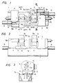
- Fig. 1 is a plan view of a shaft-like work-piece machining apparatus according to the invention.
- Fig. 5 is a front view of the same.
- Fig. 6 is a sectional view taken along the line XIII - XIII of Fig. 1.
- Figs. 1, 2 and 3 are respectively a plan view, a front view and a sectional view taken along the line III - III of Fig. 1, of a machining apparatus according to the invention.
- a bed 1 is provided with four guide surfaces 2a, 2b, 2c and 2d longitudinally formed on the bed 1 and transversely arranged with separation therebetween.
- a first tail stock 3 is located at one of the longitudinally opposite ends of the bed 1 and is arranged to be longitudinally movable over both the first guide surface 2a and the third guide surface 2c located on the rear side of the second guide surface 2b which is adjacent to the first guide surface 2a.
- a second tail stock 4 is located at the other longitudinal end of the bed 1 and which is arranged to be longitudinally movable over the other guide surfaces, i.e. over both the second guide surface 2b and the fourth guide surface 2d located on the rear side of the third guide surface 2c.
- the tail stocks 3 and 4 respectively have chucks 6 and 7 which are arranged on the same axis to grasp a shaft-like work piece, for example, a crank-shaft 5 at its opposite journal portions 5a respectively.
- Hydraulic cylinders individually operate the respective chuck 6 and 7, and indexing mechanisms individually index the machining position of respective crank-pins 5b of the crank-shaft 5.
- the hydraulic cylinders and indexing mechanisms are mounted within the respective tail stock 3 and 4 (the cylinders and the mechanisms are known and therefore not shown in the drawings).
- a saddle 8 is located near the first tail stock 3 between the tail stocks 3 and 4 and is arranged to be movable in the longitudinal direction of the bed 1 over both the second and fourth guide surfaces 2b and 2d.
- An NC servo-motor 9 is mounted on the bed 1 in correspondence to the saddle 8.
- a ball screw 10 arranged to be rotated by the servo-motor 9 is thread-engaged with a ball nut 11 disposed at the saddle 8, so that the saddle 8 is driven by the servo-motor 9 to move in the axial direction of the crank-shaft 5.
- a machining unit 12 is disposed on the saddle 8 so as to be movable in the direction perpendicular to the direction of movement of the saddle 8. The machining unit 12 is moved perpendicularly to the saddle 8 by a hydraulic cylinder 13 or the like provided on the saddle 8.
- crank-pins 5b of the crank-shaft 5 are cut by turning the cutting tool with the work-piece held stationary, first the tail stock 3 is moved respectively over both the first and third guide surfaces 2a and 2c and the tail stock 4 is moved over both the second and fourth guide surfaces 2b and 2d by a distance corresponding to the length of the crank-shaft 5 and are fixed respectively at positions suitable for the length of the crank-shaft 5. Thereafter the opposite journals 5a of the crank-shaft 5 are grasped by the chucks 6 and 7 of the tail stocks 3 and 4, respectively. At this time, the respective indexing mechanisms operate the chuck 6 and 7 to position the crank-shaft 5 with respect to its rotational direction, so that the crank-pins 5b of #1P and #3P are located in parallel to the core of the respective journal 5a.
- the saddle 8 By driving the servo-motor 9 to rotate the ball screw 10, the saddle 8 is moved in the direction of the arrow A of Fig. 1 so that the cutting tool 38 is positioned so as to be opposite to one of the crank-pins 5b, for example, crank-pin 5b of #4P.
- the hydraulic cylinder 13 After completion of positioning of the cutting tool 38 with respect to the #4P crank-pin 5b, the hydraulic cylinder 13 is operated to move the machining unit 12 to such a position that the axis of the hollow main spindle 15 accords with the center of the crank-pins 5b of #1P and #4P to thereby shift the operation of the machine tool into a crank-pin cutting mode.
- the servo-motor 9 is operated to move the saddle 8 form #4P to #1P, and the cutting tool 38 is positioned so as to be enabled to cut #1P. Thereafter, the servo-motor 25 is operated in the same manner as described above to thereby perform desired cutting machining.
- the indexing mechanisms for the respective chucks 6 and 7 are operated to perform 180° turn indexing of the crank-shaft 5 so that the crank-pins 5b of #2P and #3P are located at the rotational center of the hollow main spindle 15. Thereafter, the servo-motors 9 and 25 are operated in the same manner as described above to thereby cut the #2P and #3P.
- the machining unit 12 which turns around the crank-pins 5b of the crank-shaft 5 to cut, for example, the third and the fourth pins 5b (#3P and 4P) is disposed on the first saddle 8 so as to be movable in the direction perpendicular to the direction of movement of the saddle 8.
- the machining unit 12 is moved by the hydraulic cylinder 13 or the like provided on the saddle 8.
- a second saddle 14 is located between the tail stocks 3 and 4 near the second tail stock 3 and is disposed over both the first and third guide surfaces 2a and 2c of the bed 1 so as to be longitudinally movable relative to the bed 1.
- the second saddle 14 is provided with a servo-motor 15, a ball screw 16 rotated by the servo-motor 15, and a ball nut 17 fitted to the ball screw 16 and fixed to the saddle 14.
- a second machining unit 18 is disposed on the second saddle 14 so as to be movable in the direction perpendicular to the direction of movement of the saddle 14.
- the first and second machining units 12 and 18 have insertion holes 12a and 18a for inserting chucks 6 and 7 Of the first and second tail stocks 3 and 4 therein, respectively.
- Tool heads (not shown) rotated around the crank-shaft 5 and simultaneously fed inwards in the diametrical direction of the crank-shaft 5 are mounted on the inner side of the insertion holes 12a and 18a, respectively.
- an anti-vibration unit 20 is mounted on the work side of the first saddle 8 to prevent the vibration of the crank-shaft 5.
- the anti-vibration unit 20 has pressing metal bearings 20a and 20b for holding the journal 5a of the crank-shaft 5 therebetween.
- the servo-motor 9 is first operated to rotate the ball screw 10 to thereby move the saddle 8 in the direction of the arrow A of Fig. 1 on the second and fourth guide surfaces 2b and 2d so that the cutting tool T is positioned in opposition to one of the crank-pins 5b, for example, #4P.
- the hydraulic cylinder 13 is operated to move the first machining unit 12 to a position near to the outer circumference of the #4P crank-pin 5b so that the mode of the machine tool is shifted into a crank-pin cutting mode.
- the pressing metal bearing 20a and 20b are urged against a journal between the #3P and #4P crank-pins 5b.
- the servo-motor 12b for cutting operation is started in response to the setting of the machine tool to the cutting mode so that the cutting tool T in the tool head (not shown) of the machining unit 12 rotates around the #4P crank-pin 5b while being fed inwards.
- the #4P crank-pin 5b is machined.
- the tool head is stopped at a fixed position to release the anti-vibration pressing metals 20a and 20b.
- the first saddle 8 is moved again by the servo-motor 9 to make positioning of the tool head so as to come in opposition to the #1P crank-pin 5b.
- the tool head thus positioned is operated again to cut the #1P crank-pin 5b.
- crank-shaft 5 is rotated by 180 degrees by the index mechanism of the chucks 6 and 7 to make the center lines of the #2P and #3P crank-pins 5b and 5b agree with the turning center of the tool T of the machining unit 12.
- the servo-motor 12b of the machining unit 12 is operated to cut the #2 crank-pin 5b in the same manner as described above and thereafter cut the #3P crank-pin 5b.
- the cutting of all the crank-ins 5b of the crank-shaft 5 is completed.
- crank-pins 5b can be cut by use of the second machining unit 18.
- the saddle 14 is operated together with the machining unit 18 in the same manner as described above with respect to the first saddle 8 together with the machining unit 12, and therefore description thereof will be omitted.
- crank-pins 5b of the crank-shaft 5 are to be cut by both the first and second machining units 12 and 18, for example, the #4P and #3P crank-pins 5b are cut by the use of the first machining unit 12 and the #1P and #2P crank-pins 5b are cut by the use of the second machining unit 18 through the indexing mechanisms of the chucks 6 and 7 in the same manner as described above.
- the #1P and #4P crank-pins 5b are simultaneously cut by the use of both the machining units 12 and 18, whereafter the #2P and #3P crank-pins 5b and 5b are simultaneously cut by the use of both the machining units 12 and 18.
- the embodiment as described above has an advantage that the cycle time required for cutting all the crank-pins can be shortened because the two machining units 12 and 18 are used for machining the crank-pins. Furthermore, because the pair of tail stocks 3 and 4, the pair of machining units 12 and 18, and the pair of saddles 8 and 14 are disposed on the four parallel guide surfaces 2a to 2d so a to be formed like a swastika pattern, and because one of the tail stocks 3 and 4 and adjacent one of the saddles 8 and 14 are disposed to slide on independent guide surfaces, telescopic covers for protecting the guide surfaces 2a to 2d to the bed 1 from the influence of metal chips can be easily provided so that the respective tail stock 3 and 4 and the respective saddle 8 and 14 do not interfere with each other even if they approach each other.
- abrasion of the guide surfaces and partial pressing of the guide surface can be remarkably reduced compared with those in the prior art type guide surfaces which are commonly used for both the tail stock and the saddle.
- the respective tail stocks 3 and 4 and the respective saddles 8 and 14 have not a span longer than they need, saddles or the like for supporting them can be reduced in size.
- the saddles together with the tail stocks and the machining units are respectively independently loaded on the guide surfaces, the load on the guide surfaces can be reduced compared with the prior art. Accordingly, not only the guide surfaces can be reduced in size but the bed can be reduced in size as well as in weight.
- the machining unit according to the present invention is not limited to the above-described embodiment applied to the cutting of the crank-shaft.
- the invention is applicable to the cutting of other shaft-like work-pieces, such as a cylindrical cam, and the like.
- the number of the guide surfaces is not limited to the embodiment having four guide surfaces, and also the number of the machining units is not limited to the embodiment.
- pairs of parallel guide surfaces are formed in parallel to the bed so as to dispose one of the tail stocks between two guide surfaces and dispose adjacent one of the machining units between different two guide surfaces
- abrasion of the respective guide surface can be remarkably reduced. Accordingly, high machining accuracy can be maintained, and the support part for the tail stocks and the machining units can be reduced in size. Accordingly, the load on the guide surfaces can be reduced, and the guide surfaces can be reduced in size as well as in weight easily.
Claims (5)
- Bearbeitungsgerät mit einem ersten und einem zweiten Reitstock (3, 4) zur Abstützung gegenüberliegender, zu bearbeitender wellenartiger Werkstücke (5), und mindestens zwei Bearbeitungseinheiten (12, 18) zur Bearbeitung eines äußeren Umfanges des Werkstückes, die an unterschiedlichen Positionen zwischen den Reitstücken angeordnet sind, dadurch gekennzeichnet, daß zwei Paare paralleler Führungsoberflächen vorgesehen sind, die an einem Bett (1) befestigt sind zur Führung der Reitstöcke und der Bearbeitungseinheiten, um eine Bewegung entlang des Bettes zu ermöglichen, wobei nebeneinanderliegende Reitstöcke und Bearbeitungseinheiten an verschiedenen Paaren der Führungsflächen befestigt sind, die beiden Paare der Führungsoberflächen hintereinander eine erste Führungsfläche (2a), eine zweite Führungsfläche (2b), eine dritte Führungsfläche (2c) und eine vierte Führungsfläche (2d) beinhalten, der erste Reitstock (3) an einem der gegenüberliegenden Längsenden des Bettes (1) plaziert ist und in Längsrichtung über die erste Führungsfläche (2a) und die dritte Führungsfläche (2c) bewegbar und an beiden geführt angeordnet ist, und der zweite Reitstock (4) am anderen Ende des Bettes (1) plaziert ist und in Längsrichtung über die anderen Führungsflächen, das heißt die zweite Führungsfläche (2b) und die vierte Führungsfläche (2d) bewegbar und an beiden geführt ist.
- Bearbeitungsgerät nach Anspruch 1, dadurch gekennzeichnet, daß die zweite Führungsfläche (2b) hinter der ersten Führungsfläche (2a) angeordnet ist, daß die dritte Führungsfläche (2c) hinter der zweiten Führungsfläche (2b) angeordnet ist, und daß die vierte Führungsfläche (2d) hinter der dritten Führungsfläche (2c) angeordnet ist.
- Bearbeitungsgerät nach Anspruch 1 oder 2, dadurch gekennzeichnet, daß ein Schlitten (8) nahe des ersten Reitstockes (3) zwischen den Reitstöcken (3, 4) angeordnet ist zur Ermöglichung einer Bewegung in Längsrichtung des Bettes (1) über die zweite und vierte Führungsfläche (2b, 2d), und daß die Bearbeitungseinheit (12) auf dem Schlitten (8) angeordnet ist.
- Bearbeitungsgerät nach einem der Ansprüche 1 bis 3, dadurch gekennzeichnet, daß ein zweiter Schlitten (14) zwischen dem ersten Reitstock (3) und dem zweiten Reitstock (4) und über der ersten und dritten Führungsfläche (2a, 2c) des Bettes (1) angeordnet ist zur Ermöglichung einer Längsbewegung relativ zu dem Bett (1), und daß die zweite Bearbeitungseinheit (18) auf dem zweiten Schlitten (14) angeordnet ist.
- Gerät nach Anspruch 3 oder 4, dadurch gekennzeichnet, daß der erste Schlitten (8) und der zweite Schlitten (14) mit einem Servomotor (15), einer durch den Servomotor (15) rotierten Kugelumlaufspindel (16) und einer an der Kugelumlaufspindel und dem Schlitten angebrachten Kugelmutter (17) versehen ist, derart, daß die entsprechenden Bearbeitungseinheiten (12, 18) in der Richtung senkrecht zur Bewegungsrichtung des ersten Schlittens (8) und des zweiten Schlittens (14) bewegbar sind.
Applications Claiming Priority (9)
| Application Number | Priority Date | Filing Date | Title |
|---|---|---|---|
| JP42724/86 | 1986-02-27 | ||
| JP1986027744U JPH0410986Y2 (de) | 1986-02-27 | 1986-02-27 | |
| JP61042724A JPS62199302A (ja) | 1986-02-27 | 1986-02-27 | 工作機械の工具送り装置 |
| JP27744/86U | 1986-02-27 | ||
| JP15771386A JPH07106482B2 (ja) | 1986-07-04 | 1986-07-04 | 工作機械の工具送り装置 |
| JP157713/86 | 1986-07-04 | ||
| JP15771286A JPH07106481B2 (ja) | 1986-07-04 | 1986-07-04 | 工作機械の工具送り装置 |
| JP157712/86 | 1986-07-04 | ||
| EP87102542A EP0235719B1 (de) | 1986-02-27 | 1987-02-23 | Werkzeugschlittenvorrichtung in einer Werkzeugmaschine |
Related Parent Applications (2)
| Application Number | Title | Priority Date | Filing Date |
|---|---|---|---|
| EP87102542.5 Division | 1987-02-23 | ||
| EP87102542A Division EP0235719B1 (de) | 1986-02-27 | 1987-02-23 | Werkzeugschlittenvorrichtung in einer Werkzeugmaschine |
Publications (3)
| Publication Number | Publication Date |
|---|---|
| EP0442542A2 EP0442542A2 (de) | 1991-08-21 |
| EP0442542A3 EP0442542A3 (de) | 1991-09-04 |
| EP0442542B1 true EP0442542B1 (de) | 1994-12-14 |
Family
ID=27458753
Family Applications (2)
| Application Number | Title | Priority Date | Filing Date |
|---|---|---|---|
| EP87102542A Expired - Lifetime EP0235719B1 (de) | 1986-02-27 | 1987-02-23 | Werkzeugschlittenvorrichtung in einer Werkzeugmaschine |
| EP91106934A Expired - Lifetime EP0442542B1 (de) | 1986-02-27 | 1987-02-23 | Bearbeitungsgerät |
Family Applications Before (1)
| Application Number | Title | Priority Date | Filing Date |
|---|---|---|---|
| EP87102542A Expired - Lifetime EP0235719B1 (de) | 1986-02-27 | 1987-02-23 | Werkzeugschlittenvorrichtung in einer Werkzeugmaschine |
Country Status (5)
| Country | Link |
|---|---|
| US (1) | US4800789A (de) |
| EP (2) | EP0235719B1 (de) |
| KR (1) | KR950004527B1 (de) |
| AT (2) | ATE115453T1 (de) |
| DE (2) | DE3750883T2 (de) |
Cited By (1)
| Publication number | Priority date | Publication date | Assignee | Title |
|---|---|---|---|---|
| CN109128228A (zh) * | 2018-09-05 | 2019-01-04 | 芜湖福祥模具科技有限公司 | 一种用于冲压模具制造的卧式车床 |
Families Citing this family (5)
| Publication number | Priority date | Publication date | Assignee | Title |
|---|---|---|---|---|
| US20010042424A1 (en) * | 1998-09-04 | 2001-11-22 | Sheehan | Reduced vibration lathe |
| JP2002096202A (ja) * | 2000-09-18 | 2002-04-02 | Mori Seiki Co Ltd | 工作機械の主軸台案内装置 |
| EP1349687A4 (de) | 2000-12-18 | 2005-06-01 | Cardemon Inc Dba Car Tec Co | Einstellverfahren und vorrichtung für ein bohrwerkzeug |
| DE10317318A1 (de) * | 2003-04-11 | 2004-10-21 | Gebr. Heller Maschinenfabrik Gmbh | Maschine zur Bearbeitung von Werkstücken, insbesondere von Kurbel- und Nockenwellen, mit mindestens einem Innen-Rundfräswerkzeug |
| CN114905286B (zh) * | 2022-05-23 | 2023-10-13 | 杭州泰博包装材料有限公司 | 一种一体式铝管修整装置 |
Citations (1)
| Publication number | Priority date | Publication date | Assignee | Title |
|---|---|---|---|---|
| GB1559550A (en) * | 1976-12-24 | 1980-01-23 | Heller Geb Gmbh Maschf | Crankshaft milling machine |
Family Cites Families (15)
| Publication number | Priority date | Publication date | Assignee | Title |
|---|---|---|---|---|
| US53058A (en) * | 1866-03-06 | Improved device for securing the tail-stocks of lathes | ||
| GB190213437A (en) * | 1902-06-13 | 1902-07-17 | John Lester Osgood | Improvements in Lathes and Similar Machine Tools |
| US2148293A (en) * | 1937-05-06 | 1939-02-21 | Leblond Mach Tool Co R K | Tool feed mechanism for lathes |
| BE519289A (de) * | 1952-04-29 | |||
| DE1652674B2 (de) * | 1968-01-04 | 1972-08-24 | Hoesch Maschinenfabrik Deutschland Ag, 4600 Dortmund | Schwere drehmaschine, insbesondere walzendrehmaschine |
| GB1328015A (en) * | 1971-06-26 | 1973-08-22 | Clarke Chapman John Thompson L | Methods of and apparatus for flash removal |
| GB1380523A (en) * | 1973-02-07 | 1975-01-15 | Santana A Z | Apparatus for cutting and or bevelling pipes |
| US3848489A (en) * | 1973-03-09 | 1974-11-19 | A Santana | Rotary machine tool |
| DE2500895A1 (de) * | 1975-01-10 | 1976-07-15 | Heyligenstaedt & Co | Bearbeitungszentrum fuer dreh- und schleifarbeiten insbesondere zur walzenbearbeitung |
| DE2551250A1 (de) * | 1975-11-14 | 1977-05-26 | Boehringer Gmbh Geb | Werkzeugmaschine und fraeswerkzeug zum bearbeiten der zapfen einer kurbelwelle nach dem wirbelverfahren |
| DE2822346C2 (de) * | 1978-05-22 | 1985-09-05 | GFM Gesellschaft für Fertigungstechnik und Maschinenbau GmbH, Steyr | Elektrische numerische Programmsteuerung für Kurbelwellenfräsmaschinen und Kurbelwellen-Schleifmaschinen |
| AT358361B (de) * | 1979-03-08 | 1980-09-10 | Gfm Fertigungstechnik | Verfahren zum bearbeiten von mehrfach gekroepften kurbelwellen |
| ATA733179A (de) * | 1979-11-19 | 1983-07-15 | Gfm Fertigungstechnik | Werkzeugmaschine zur spanenden bearbeitung von kurbelwellen od. dgl. |
| JPS5715601A (en) * | 1980-06-26 | 1982-01-27 | Komatsu Ltd | Turning work device for crankshaft |
| BR8108057A (pt) * | 1981-12-11 | 1983-09-13 | Romi Ind | Maquina de tornear |
-
1987
- 1987-02-23 EP EP87102542A patent/EP0235719B1/de not_active Expired - Lifetime
- 1987-02-23 AT AT91106934T patent/ATE115453T1/de not_active IP Right Cessation
- 1987-02-23 AT AT87102542T patent/ATE71570T1/de not_active IP Right Cessation
- 1987-02-23 EP EP91106934A patent/EP0442542B1/de not_active Expired - Lifetime
- 1987-02-23 DE DE3750883T patent/DE3750883T2/de not_active Expired - Fee Related
- 1987-02-23 DE DE8787102542T patent/DE3775943D1/de not_active Expired - Fee Related
- 1987-02-27 KR KR1019870001721A patent/KR950004527B1/ko not_active IP Right Cessation
- 1987-02-27 US US07/019,809 patent/US4800789A/en not_active Expired - Fee Related
Patent Citations (1)
| Publication number | Priority date | Publication date | Assignee | Title |
|---|---|---|---|---|
| GB1559550A (en) * | 1976-12-24 | 1980-01-23 | Heller Geb Gmbh Maschf | Crankshaft milling machine |
Cited By (1)
| Publication number | Priority date | Publication date | Assignee | Title |
|---|---|---|---|---|
| CN109128228A (zh) * | 2018-09-05 | 2019-01-04 | 芜湖福祥模具科技有限公司 | 一种用于冲压模具制造的卧式车床 |
Also Published As
| Publication number | Publication date |
|---|---|
| EP0442542A3 (de) | 1991-09-04 |
| ATE71570T1 (de) | 1992-02-15 |
| ATE115453T1 (de) | 1994-12-15 |
| KR950004527B1 (ko) | 1995-05-02 |
| DE3750883T2 (de) | 1995-05-04 |
| EP0442542A2 (de) | 1991-08-21 |
| EP0235719B1 (de) | 1992-01-15 |
| DE3750883D1 (de) | 1995-01-26 |
| US4800789A (en) | 1989-01-31 |
| EP0235719A2 (de) | 1987-09-09 |
| EP0235719A3 (en) | 1987-11-25 |
| KR870007754A (ko) | 1987-09-21 |
| DE3775943D1 (de) | 1992-02-27 |
Similar Documents
| Publication | Publication Date | Title |
|---|---|---|
| US5025689A (en) | Method and apparatus for machining axially symmetrical parts | |
| US5058261A (en) | Machine tool | |
| US4612832A (en) | Multiple-function machine tool with two spindles | |
| US4719676A (en) | Flexible machining system | |
| EP0821631B1 (de) | Verfahren und vorrichtung zur bearbeitung von löchern in kurbenwellen | |
| US6640678B2 (en) | Lathe with two-opposed spindles | |
| US4612690A (en) | Multiple spindle machine tool | |
| EP0442542B1 (de) | Bearbeitungsgerät | |
| JPS5852761B2 (ja) | クランクシヤフト加工機械 | |
| US4953274A (en) | Machine tool with two workpiece spindles | |
| JPS5933481B2 (ja) | 自動施盤 | |
| US4130033A (en) | Multiple spindle automatic screw machine | |
| EP0433722B1 (de) | Mehrspindel-Drehautomat | |
| US5758554A (en) | Machine tool and method for machining a long-shafted workpiece | |
| JP4271402B2 (ja) | 細物ワーク加工用の2主軸対向旋盤 | |
| JP2023045438A (ja) | 工作機械 | |
| US20060143888A1 (en) | Machine for rough-machining and planning functional elements of crankshafts or camshafts | |
| GB2262061A (en) | Double spindle type lathe | |
| US4614467A (en) | Cam milling machine | |
| GB2181372A (en) | Flexible machining system | |
| JPH0410986Y2 (de) | ||
| US3832919A (en) | Orbital crankshaft lathe mechanism and methods of machining | |
| JP2688616B2 (ja) | ワークの二軸加工法 | |
| US3013457A (en) | Crankshaft lathe and method of operation | |
| US6736575B2 (en) | Linear broach machining system |
Legal Events
| Date | Code | Title | Description |
|---|---|---|---|
| PUAI | Public reference made under article 153(3) epc to a published international application that has entered the european phase |
Free format text: ORIGINAL CODE: 0009012 |
|
| PUAL | Search report despatched |
Free format text: ORIGINAL CODE: 0009013 |
|
| 17P | Request for examination filed |
Effective date: 19910429 |
|
| AC | Divisional application: reference to earlier application |
Ref document number: 235719 Country of ref document: EP |
|
| AK | Designated contracting states |
Kind code of ref document: A2 Designated state(s): AT CH DE FR GB IT LI |
|
| AK | Designated contracting states |
Kind code of ref document: A3 Designated state(s): AT CH DE FR GB IT LI |
|
| RIN1 | Information on inventor provided before grant (corrected) |
Inventor name: NAKANO, KYUZO C/O NIIGATA ENGINEERING CO., LTD. |
|
| RHK1 | Main classification (correction) |
Ipc: B23B 17/00 |
|
| 17Q | First examination report despatched |
Effective date: 19930423 |
|
| GRAA | (expected) grant |
Free format text: ORIGINAL CODE: 0009210 |
|
| AC | Divisional application: reference to earlier application |
Ref document number: 235719 Country of ref document: EP |
|
| AK | Designated contracting states |
Kind code of ref document: B1 Designated state(s): AT CH DE FR GB IT LI |
|
| REF | Corresponds to: |
Ref document number: 115453 Country of ref document: AT Date of ref document: 19941215 Kind code of ref document: T |
|
| REF | Corresponds to: |
Ref document number: 3750883 Country of ref document: DE Date of ref document: 19950126 |
|
| ITTA | It: last paid annual fee | ||
| ITF | It: translation for a ep patent filed |
Owner name: SOCIETA' ITALIANA BREVETTI S.P.A. |
|
| ET | Fr: translation filed | ||
| PLBE | No opposition filed within time limit |
Free format text: ORIGINAL CODE: 0009261 |
|
| STAA | Information on the status of an ep patent application or granted ep patent |
Free format text: STATUS: NO OPPOSITION FILED WITHIN TIME LIMIT |
|
| 26N | No opposition filed | ||
| PGFP | Annual fee paid to national office [announced via postgrant information from national office to epo] |
Ref country code: DE Payment date: 19991230 Year of fee payment: 14 |
|
| PGFP | Annual fee paid to national office [announced via postgrant information from national office to epo] |
Ref country code: GB Payment date: 20000203 Year of fee payment: 14 |
|
| PGFP | Annual fee paid to national office [announced via postgrant information from national office to epo] |
Ref country code: CH Payment date: 20000209 Year of fee payment: 14 |
|
| PGFP | Annual fee paid to national office [announced via postgrant information from national office to epo] |
Ref country code: AT Payment date: 20000214 Year of fee payment: 14 |
|
| PGFP | Annual fee paid to national office [announced via postgrant information from national office to epo] |
Ref country code: FR Payment date: 20000229 Year of fee payment: 14 |
|
| PG25 | Lapsed in a contracting state [announced via postgrant information from national office to epo] |
Ref country code: GB Free format text: LAPSE BECAUSE OF NON-PAYMENT OF DUE FEES Effective date: 20010223 Ref country code: AT Free format text: LAPSE BECAUSE OF NON-PAYMENT OF DUE FEES Effective date: 20010223 |
|
| PG25 | Lapsed in a contracting state [announced via postgrant information from national office to epo] |
Ref country code: LI Free format text: LAPSE BECAUSE OF NON-PAYMENT OF DUE FEES Effective date: 20010228 Ref country code: CH Free format text: LAPSE BECAUSE OF NON-PAYMENT OF DUE FEES Effective date: 20010228 |
|
| REG | Reference to a national code |
Ref country code: CH Ref legal event code: PL |
|
| GBPC | Gb: european patent ceased through non-payment of renewal fee |
Effective date: 20010223 |
|
| PG25 | Lapsed in a contracting state [announced via postgrant information from national office to epo] |
Ref country code: FR Free format text: LAPSE BECAUSE OF NON-PAYMENT OF DUE FEES Effective date: 20011031 |
|
| REG | Reference to a national code |
Ref country code: FR Ref legal event code: ST |
|
| PG25 | Lapsed in a contracting state [announced via postgrant information from national office to epo] |
Ref country code: DE Free format text: LAPSE BECAUSE OF NON-PAYMENT OF DUE FEES Effective date: 20011201 |
|
| PG25 | Lapsed in a contracting state [announced via postgrant information from national office to epo] |
Ref country code: IT Free format text: LAPSE BECAUSE OF NON-PAYMENT OF DUE FEES Effective date: 20050223 |