EP0442535B1 - Fruchtsaftpresse mit einem Kopf - Google Patents
Fruchtsaftpresse mit einem Kopf Download PDFInfo
- Publication number
- EP0442535B1 EP0442535B1 EP91104430A EP91104430A EP0442535B1 EP 0442535 B1 EP0442535 B1 EP 0442535B1 EP 91104430 A EP91104430 A EP 91104430A EP 91104430 A EP91104430 A EP 91104430A EP 0442535 B1 EP0442535 B1 EP 0442535B1
- Authority
- EP
- European Patent Office
- Prior art keywords
- support structure
- reciprocating support
- orifice tube
- upper cup
- cup
- Prior art date
- Legal status (The legal status is an assumption and is not a legal conclusion. Google has not performed a legal analysis and makes no representation as to the accuracy of the status listed.)
- Expired - Lifetime
Links
- 235000011389 fruit/vegetable juice Nutrition 0.000 title claims abstract description 71
- 230000033001 locomotion Effects 0.000 claims description 18
- 238000012545 processing Methods 0.000 claims description 5
- 235000013399 edible fruits Nutrition 0.000 abstract description 33
- 235000015203 fruit juice Nutrition 0.000 description 6
- 235000020971 citrus fruits Nutrition 0.000 description 4
- 238000000605 extraction Methods 0.000 description 4
- 230000007246 mechanism Effects 0.000 description 3
- 230000008901 benefit Effects 0.000 description 2
- 230000006835 compression Effects 0.000 description 2
- 238000007906 compression Methods 0.000 description 2
- 238000004519 manufacturing process Methods 0.000 description 2
- 241000196324 Embryophyta Species 0.000 description 1
- 230000009471 action Effects 0.000 description 1
- 230000004888 barrier function Effects 0.000 description 1
- 230000000903 blocking effect Effects 0.000 description 1
- 230000001419 dependent effect Effects 0.000 description 1
- 238000011161 development Methods 0.000 description 1
- 230000018109 developmental process Effects 0.000 description 1
- 230000009977 dual effect Effects 0.000 description 1
- 230000005484 gravity Effects 0.000 description 1
- 238000009434 installation Methods 0.000 description 1
- 239000007788 liquid Substances 0.000 description 1
- 238000012856 packing Methods 0.000 description 1
- 230000000284 resting effect Effects 0.000 description 1
- 238000012552 review Methods 0.000 description 1
- 239000011343 solid material Substances 0.000 description 1
Images


Classifications
-
- A—HUMAN NECESSITIES
- A23—FOODS OR FOODSTUFFS; TREATMENT THEREOF, NOT COVERED BY OTHER CLASSES
- A23N—MACHINES OR APPARATUS FOR TREATING HARVESTED FRUIT, VEGETABLES OR FLOWER BULBS IN BULK, NOT OTHERWISE PROVIDED FOR; PEELING VEGETABLES OR FRUIT IN BULK; APPARATUS FOR PREPARING ANIMAL FEEDING- STUFFS
- A23N1/00—Machines or apparatus for extracting juice
- A23N1/003—Machines or apparatus for extracting juice especially for citrus fruits
Definitions
- the present invention relates to a single head juice extractor comprising a frame means, lower cup means mounted to said frame means, juice collecting sump mounted to said frame means proximate to said lower cup means, orifice tube means mounted for reciprocal movement through said juice collecting sump, upper cup reciprocating support structure supported for reciprocal motion on said frame means and means to reciprocate said upper cup reciprocating support structure.
- a juice extractor according to US-A-4,300,449 comprises a pair of opposed cups in order to force the contents of the fruit as squeezed into a strainer tube.
- An orifice tube can be driven upwardly within the strainer tube to force juice and some solid material through the perforation in the strainer tube.
- a dual chamber connected to the strainer tube manifold enables two juice grades to be separately extracted from each fruit. From this reference it is known how to actuate exactly the upper cups and the orifice tube.
- a further apparatus for extracting juice and peel oil from citrus fruits is disclosed in GB-A-753,988.
- a cross head carrying upper cup can be moved downwardly by means of follower rollers and cam discs which are connected to a shaft. This shaft is driven by an electric motor through a chain and sprocket drive.
- a crossbeam holding orifice tubes which extend into finisher tubes is reciprocated by rods which are connected at their lower ends for conjoint movement by a transverse bar.
- the orifice tubes can be moved in timed relation with the upper cups since they are each controlled by cams keyed on the same shaft.
- a strainer tube forming a part of a juice separating apparatus slidably receives a pressure exerting member in the form of an orifice tube which is fastened to a crosshead.
- the crosshead is operatively connected with the upper cup supporting head for vertical reciprocation in timed relation therewith in a manner not shown in this reference.
- US-A-4,700,620 discloses another citrus fruit extractor including an upper cup reciprocably movable towards a lower cup by means of a shaft and cam mechanism.
- An orifice tube which is slidably fitted within a strainer tube has its lower end connected to a guide rod which in turn extends through a beam which is reciprocated by rods actuated by a cam to raise and lower the beam in synchronism with the cup operation.
- a cup shaped magnet is provided to reasably retain the orifice tube in its upper travel limit. During the course of compressing a fruit between the cups the liquid pressure is sufficient to overcome the latching force of the magnet causing the orifice tube to drop against an elastomeric member which cushions the gravity force of the descending orifice tube.
- the prior art two cup interdigitating juice extractors are large machines that have been designed for high volume production situations. Numbers of these large, high volume juice extractors would be ganged together in the juice room of a juice producer to take advantage of the economics of scale of shipping fruit to a central location, storage and processing of large quantities of fruit juice and packing and shipping of the juice.
- This invention is not necessarily directed at providing equipment for a large juice extractor plant, but, as stated earlier, is designed for the high yield production of juice and high quality juice at relatively low volumes for point of sale installations.
- the problem underlying the invention is solved by the fact that the upper cup reciprocating support structure is movable laterally adjacent said lower cup means and that the upper cup means is supported in a cantilevered manner by said upper cup reciprocating support structure above said lower cup means.
- point of sale juice extractors are not as selectice in juice extractors--that is, extracting juice having low oil content and low incidences of seeds and pulp--as the instant invention.
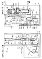
- Figure 1 is a partially fragmented and sectioned front elevation view (with drive elements left off for clarity) of the fruit juice extracting apparatus.
- Figure 2 is a partially fragmented and sectioned side elevation view of the fruit juice extrator including portions of the drive mechanism.
- FIG 3 is a partially fragmented rear elevation view of the significant portions, for purposes of this specification, of the fruit juice extractor of Figure 1.
- Figures 4 A-E are schematic presentations of relative positions of the fruit juice extractor elements as they are driven through a typical extraction cycle.
- the juice extractor generally 10 is provided with a housing 12 supported on a base 14, which houses and supports the extractor apparatus.
- the actual extractor apparatus includes well known components including an upper cup 16, a lower cup 18, a juice collecting sump 20, a strainer tube 22 and an orifice tube 24.
- a conventional tubular knife 26 and a receiver for the knife 26 are also provided.
- the upper cup and the lower cup are each formed of intersticial or interdigitating fingers that fit between adjacent fingers of the other cup when the cups are urged together to squeeze the juice out of the fruit.
- the lower cup 18 is fixedly mounted to the base 14 and housing 12 through the use of a mounting plate 40 which is fastened to an internal wall 41 of the juice extractor.
- the juice sump 20 and its contained strainer tube 22 are attached to the mounting plate 40.
- the internal wall 41 is fastened to the frame or housing 12 of the juice extractor.
- the juice extraction process proceeds as follows.
- the strainer tube 22 hosting the tubular knife 26 will be forced into the peel of the fruit to sever the peel.
- the contents of the peel--that is, the fruit-- will be forced into the strainer tube 22 as the upper cup 16 is urged into the lower cup 18.
- the fruit is substantially all contained in the strainer tube 22 while the peel of the fruit is extruded between the fingers of the cups for ultimate collection and appropriate disposal.
- the fruit now contained in the strainer tube 22 is compressed upwardly by the orifice tube 24 causing the fruit juice to be extracted from or squeezed from the entrapped fruit in the strainer tube 22 and drained through small diameter orifices in the strainer tube into the juice collecting sump 20.
- Figure 1 shows components that are unique to the presented preferred embodiment including a feed chute generally 30, an upper cup reciprocating support structure 32, a fruit lift 34 that is attached to and reciprocates with the upper cup reciprocating support structure 32, and a fruit bridge 36.
- the orifice tube 24 is mounted for reciprocal movement on an orifice tube reciprocating support structure 38.
- FIGs 2 and 3 wherein like reference characters as recited in Figure 1 refer to the same parts, are views of the juice extractor that illustrate the invention being presented.
- the drive motor 42 which in a preferred embodiment could be a gear motor; driven sprockets; an upper cup reciprocating support structure driven sprocket 44 or upper cup sprocket; and an orifice tube reciprocating support structure drive sprocket 46 or orifice tube sprocket.
- the orifice tube sprocket 46 turns a shaft 48, supported in a bearing block means 50, which has a crank arm 52 fixedly mounted to the shaft 48. Attached to the outboard end of the crank arm 52 is a rod 54 that connects the crank arm 52 to the orifice tube reciprocating support structure 38.
- the orifice tube reciprocating support structure 38 is guided for reciprocal movement through the use of a pair of bearing columns, one shown as 56 which passes through bushed bearing passages such as 58 in the orifice tube reciprocating support structure 38.
- the orifice tube reciprocating support structure 38 extends through an aperture 43 in the internal wall 41. It is apparent that as the motor drives the orifice tube sprocket 46 through the expedient of the chain 60, the orifice tube 24 will be moved vertically upwardly and downwardly by the linkage just described.
- the "action" of the upper cup is controlled and driven by the upper cup sprocket 44 which is also driven, and is simultaneously driven by endless chain 60 through the motor 42.
- the upper cup sprocket 44 is journalled on a shaft 62 which is supported by a mounting block 64 which is supported by supports 66 and 68 mounted to the housing 12 of the juice extractor.
- the shaft 62 is fastened at its other end to an upper cup drive crank arm 70.
- An upper cup drive rod 72 connects the upper cup drive crank arm 70 to the upper cup reciprocating support structure 32 to which the upper cup 16 is attached.
- the upper cup reciprocating support structure 32 is guided by bearing columns to 74 and 76 which pass through bushed bearing apertures 78 and 80 in the upper cup reciprocating support structure 32. A portion of the reciprocating support structure, that portion to which the upper cup is attached, passes through aperture 82 in the internal wall 41.
- the upper cup sprocket 44 in a preferred embodiment, is twice the diameter of the orifice tube sprocket 46, having 48 teeth and 24 teeth respectively.
- the gear motor 42 has an output of 100 RPM with a 14 tooth drive sprocket.
- the gear motor is a one and a half horse power motor this preferred embodiment configuration. Other gear ratios are possible.
- the orifice tube sprocket will rotate twice for each machine cycle.
- the orifice tube 24 would only be driven through the strainer tube 22 once per cycle but with the 1:2 ratio of the instant invention, the orifice tube 24 will be cycled to actually squeeze the fruit in the strainer tube 22 at a speed to simulate a cam motion used in commercial extractors to obtain the same juice yield as a commercial extractor.
- FIGS 4A-4E One machine cycle of juice extraction from a single fruit is shown somewhat pictorially in Figures 4A-4E.
- the fruit for instance an orange 84
- the orange to be squeezed is held on the fruit chute of the fruit lift 34, which, as shown in Figure 1 is attached to the upper cup reciprocating support structure 32 so that it moves with the upper cup reciprocating support structure 32.
- the fruit lift 34 will lift the orange to the top of the fruit bridge 36 and allow the orange to roll across the fruit bridge 36 to nest in the lower cup 18.
- the fruit bridge has a barrier wall portion that blocks the fruit from leaving the fruit lift 34 until the fruit reaches the fruit bridge transverse surface.
- Figure 4B shows the upper cup sprocket 44 at top dead center and this could be considered the start of a complete cycle.
- the fruit lift 34 has a fruit lift wall blocking the next orange from leaving the feed chute 30, the orifice tube 24 is at an up position with its orifice tube sprockets 46 at 0 into its first of two rotations per each machine cycle.
- crank arms 52 and 70 could be rotated around their respective shafts to adjust the timing of the relationship between the squeezing of the fruit and the orifice tube compression cycle.
Landscapes
- Life Sciences & Earth Sciences (AREA)
- Chemical & Material Sciences (AREA)
- Engineering & Computer Science (AREA)
- Food Science & Technology (AREA)
- Polymers & Plastics (AREA)
- Apparatuses For Bulk Treatment Of Fruits And Vegetables And Apparatuses For Preparing Feeds (AREA)
- Non-Alcoholic Beverages (AREA)
Claims (14)
- Fruchtsaftpresse mit einem Kopf, welche eine Rahmeneinrichtung (12), eine an der Rahmeneinrichtung angeordnete untere Bechereinrichtung (18), einen Fruchtsaft-Sammelbehälter (20), der an der Rahmeneinrichtung (12) nahe der unteren Bechereinrichtung (18) angeordnet ist, eine Lochrohreinrichtung (24), welche durch den Fruchtsaft-Sammelbehälter (20) hin- und herbewegbar angeordnet ist, eine den oberen Becher hin- und herbewegende Stützstruktur (32), welche zwecks Hin- und Herbewegung an der Rahmeneinrichtung (12) abgestützt ist, und eine Einrichtung zum Hin- und Herbewegen der Stützstruktur (32) umfaßt, welche den oberen Becher hin- und herbewegt,
dadurch gekennzeichnet, daß
die den oberen Becher hin- und herbewegende Stützstruktur (32) seitlich neben der unteren Bechereinrichtung (18) bewegbar ist, und daß
die obere Bechereinrichtung (16) auslegerartig von der den oberen Becher hin- und herbewegenden Stützstruktur (32) oberhalb der unteren Bechereinrichtung (18) gestützt ist. - Fruchtsaftpresse nach Anspruch 1, dadurch gekennzeichnet, daß die Rahmeneinrichtung (12), welche die den oberen Becher hin- und herbewegbare Stützstruktur (32) stützt, eine Lagersäuleneinrichtung (74, 76) umfaßt.
- Fruchtsaftpresse nach Anspruch 2, dadurch gekennzeichnet, daß die den oberen Becher hin- und herbewegende Stützstruktur (32) mit Lagerflächen (78, 80) zum Kontakt mit der Rahmeneinrichtung (12) versehen ist, um so die Hin- und Herbewegung der Stützstruktur (32) auf einem vertikalen Weg steuern zu können.
- Fruchtsaftpresse nach Anspruch 3, dadurch gekennzeichnet, daß die Lagerfläche der den oberen Becher hin- und herbewegenden Stützstruktur von Durchgängen (78, 80) in dieser Stützstruktur (32) gebildet ist.
- Fruchtsaftpresse nach Anspruch 4, dadurch gekennzeichnet, daß die von der Rahmeneinrichtung (12) abgestützte und die den oberen Becher hin- und herbewegende Stützstruktur tragende Lagersäuleneinrichtung (74, 76) durch die Durchgänge (78, 80) führt.
- Fruchtsaftpresse nach Anspruch 5, gekennzeichnet durch eine ein Lochrohr hin- und herbewegende Stützstruktur (38), welche an der Rahmeneinrichtung (12) zwecks Hin- und Herbewegung abgestützt ist,
ein auslegerartig von der Stützstruktur (38) getragenes Lochrohr (24), und
eine Einrichtung zum Hin- und Herbewegen der das Lochrohr (24) hin- und herbewegenden Stützstruktur (38). - Fruchtsaftpresse nach Anspruch 6, dadurch gekennzeichnet, daß die Rahmeneinrichtung welche die das Lochrohr (24) hin- und herbewegende Stützstruktur (38) abstützt, eine Lagersäule (56) umfaßt.
- Fruchtsaftpresse nach Anspruch 7, dadurch gekennzeichnet, daß die von der Rahmeneinrichtung (12) abgestützte, das Lochrohr hin- und herbewegende Stützstruktur (38) eine Lagereinrichtung (58) in Kontakt mit der Rahmeneinrichtung (12) aufweist, um die das Lochrohr hin- und herbewegende Stützstruktur (38) auf einen vertikalen Bewegungsweg zu begrenzen.
- Fruchtsaftpresse nach Anspruch 8, dadurch gekennzeichnet, daß die Lagereinrichtung der das Lochrohr hin- und herbewegenden Stützstruktur (38) ein Durchgang (58) ist.
- Fruchtsaftpresse nach Anspruch 9, dadurch gekennzeichnet, daß die Lagersäule (56) der Rahmeneinrichtung, welche die das Lochrohr hin- und herbewegende Stützstruktur (38) hin- und herbewegt, durch den Durchgang (58) der Stützstruktur (38) geführt ist.
- Fruchtsaftpresse nach Anspruch 1, dadurch gekennzeichnet, daß die Rahmeneinrichtung (12) ein Bearbeitungsabteil, welches Fruchtsaft extrahierende Elemente (16, 18, 20, 22, 24) enthält, und ein den Antrieb enthaltendes Abteil umfaßt, welches Antriebverbindungselemente (42, 60, 44, 46, 48, 62, 52, 54, 70) zum Antreiben der den Fruchtsaft extrahierenden Elemente enthält, und daß das den Antrieb enthaltende Abteil seitlich neben dem Beabeitungsabteil angeordnet ist.
- Fruchtsaftpresse nach Anspruch 11, dadurch gekennzeichnet, daß die den Fruchtsaft extrahierenden Elemente einen fixierten Fruchtsaftsammelbehälter (20) unterhalb des unteren Bechers (18), ein fest angeordnetes Siebrohr (22), welches wenigstens teilweise in dem Fruchtsaftsammelbehälter (20) enthalten ist, ein in dem Siebrohr (22) hin- und herbewegbares Lochrohr (24) und einen oberen Becher (16) umfassen, der oberhalb des unteren Bechers (18) hin- und herbewegbar ist und damit ausgerichtet ist, und daß die Antriebverbindungselemente eine Antriebseinrichtung (42, 60, 44, 46, 62), eine Vielzahl vertikal angeordneter Lagereinrichtungen (56, 74, 76), eine das Lochrohr hin- und herbewegende Stützstruktur (38), welche an der Lagereinrichtung (56) abgestützt ist, eine an der Lagereinrichtung (74, 76) abgestützte, den oberen Becher hin- und herbewegende Stützstruktur (32), eine Kurbelarmeinrichtung (52) zur Durchführung einer Drehbewegung, welche über eine Stangeneinrichtung (54) mit der das Lochrohr hin- und herbewegenden Stützstruktur (38) verbunden ist, und eine drehbar gelagerte Becherantrieb-Kurbelarmeinrichtung (70) umfassen, welche mit der Stangeneirichtung zum Antrieb des oberen Bechers und der Kurbelarmeinrichtung in Verbindung steht, um eine vertikale Hin- und Herbewegung der den oberen Becher hin- und herbewegenden Stützstruktur (32) und der das Lochrohr hin- und herbewegenden Stützstruktur (38) zu schaffen.
- Fruchtsaftpresse nach Anspruch 12, dadurch gekennzeichnet, daß die das Lochrohr hin- und herbewegende Stützstruktur (38) einen auslegerartigen Armabschnitt aufweist, der sich von dem den Antrieb enthaltenden Abteil zu dem Bearbeitungsabteil erstreckt, wobei der auslegerartige Armabschnitt der Stützstruktur (38) an dem Lochrohr (24) befestigt ist, um eine Hin- und Herbewegung des Lochrohres zu schaffen, wenn die das Lochrohr hin- und herbewegende Stützstruktur (38) von der Antriebseinrichtung angetrieben wird.
- Fruchtsaftpresse nach Anspruch 12 oder 13, dadurch gekennzeichnet, daß die den oberen Becher hin- und herbewegende Stützstruktur (32) einen auslegerartigen Becherstützabschnitt umfaßt, welcher sich von dem den Antrieb enthaltenden Abteil zu dem Bearbeitungsabteil erstreckt und an dem oberen Becher befestigt ist, um eine Hin- und Herbewegung des oberen Bechers (16) zu schaffen, wenn die den oberen Becher hin- und herbewegende Stützstruktur (32) von der Antriebseinrichtung angetrieben wird.
Priority Applications (1)
| Application Number | Priority Date | Filing Date | Title |
|---|---|---|---|
| AT91104430T ATE89133T1 (de) | 1988-09-12 | 1989-09-12 | Fruchtsaftpresse mit einem kopf. |
Applications Claiming Priority (2)
| Application Number | Priority Date | Filing Date | Title |
|---|---|---|---|
| US242845 | 1988-09-12 | ||
| US07/242,845 US4905586A (en) | 1988-09-12 | 1988-09-12 | Single head juice extractor |
Related Parent Applications (1)
| Application Number | Title | Priority Date | Filing Date |
|---|---|---|---|
| EP89116859.3 Division | 1989-09-12 |
Publications (2)
| Publication Number | Publication Date |
|---|---|
| EP0442535A1 EP0442535A1 (de) | 1991-08-21 |
| EP0442535B1 true EP0442535B1 (de) | 1993-05-12 |
Family
ID=22916397
Family Applications (2)
| Application Number | Title | Priority Date | Filing Date |
|---|---|---|---|
| EP89116859A Expired - Lifetime EP0359198B1 (de) | 1988-09-12 | 1989-09-12 | Fruchtsaftpresse mit einem Kopf |
| EP91104430A Expired - Lifetime EP0442535B1 (de) | 1988-09-12 | 1989-09-12 | Fruchtsaftpresse mit einem Kopf |
Family Applications Before (1)
| Application Number | Title | Priority Date | Filing Date |
|---|---|---|---|
| EP89116859A Expired - Lifetime EP0359198B1 (de) | 1988-09-12 | 1989-09-12 | Fruchtsaftpresse mit einem Kopf |
Country Status (11)
| Country | Link |
|---|---|
| US (1) | US4905586A (de) |
| EP (2) | EP0359198B1 (de) |
| JP (2) | JPH069492B2 (de) |
| KR (1) | KR940010268B1 (de) |
| AT (2) | ATE75107T1 (de) |
| BR (1) | BR8904555A (de) |
| CA (1) | CA1331336C (de) |
| DE (2) | DE68906548T2 (de) |
| ES (2) | ES2042319T3 (de) |
| HK (2) | HK117894A (de) |
| IL (1) | IL91599A (de) |
Families Citing this family (37)
| Publication number | Priority date | Publication date | Assignee | Title |
|---|---|---|---|---|
| US5170700A (en) * | 1990-12-14 | 1992-12-15 | Fmc Corporation | Fluted column for juice extractor |
| ZA92550B (en) * | 1991-03-01 | 1992-10-28 | Fmc Corp | Fruit juice extraction press |
| ES2037576B1 (es) * | 1991-03-15 | 1994-01-16 | Instazum S L | Maquina para la preparacion instantanea de zumos de frutas. |
| CA2078179A1 (en) * | 1992-09-14 | 1994-03-15 | Angel Figueiras Pastor | Machine for the instantaneous preparation of fruit juices |
| US5483870A (en) * | 1995-05-12 | 1996-01-16 | Anderson; David N. | Countertop citrus juicer |
| US7628108B2 (en) * | 1995-06-19 | 2009-12-08 | Carlos Mendes Neto | Large scale modular fruit juice extraction system |
| BR9502244A (pt) * | 1995-06-19 | 1995-11-07 | Neto Carlos Mendes | Disposição em máquina extratora de suco de frutas |
| US7086328B1 (en) * | 1995-06-19 | 2006-08-08 | Carlos Neto Mendes | Filtering device for a citrus juice extraction machine |
| PT757896E (pt) * | 1995-08-07 | 2001-11-30 | Carlos Neto Mendes | Dispositivo de filtragem para uma maquina de extraccao de sumo de citrinos e configuracao de um tubo de filtracao perfurante para a extraccao de sumos de fruta |
| US5873302A (en) * | 1996-02-26 | 1999-02-23 | Fmc Corporation | Pulp wash system |
| ES2130077B1 (es) * | 1997-06-26 | 2000-01-16 | Catarain Arregui Esteban | Maquina automatica suministradora de zumos naturales. |
| US5996485A (en) * | 1998-05-29 | 1999-12-07 | Fmc Corporation | Juice extractor with alignment bearing |
| US5992311A (en) * | 1998-05-29 | 1999-11-30 | Fmc Corporation | Juice extractor with hydraulic control of extraction back pressure |
| US5970861A (en) * | 1998-05-29 | 1999-10-26 | Fmc Corporation | Juice extractor with safety release member |
| US6663596B2 (en) | 2001-08-13 | 2003-12-16 | Scimed Life Systems, Inc. | Delivering material to a patient |
| ITMI20020619A1 (it) * | 2002-03-25 | 2003-09-25 | Michele Gurrieri | Macchina per la spremitura di frutti in particolare agrumi con dispositivo di lavaggio |
| BRPI0400635B1 (pt) * | 2004-02-09 | 2014-11-11 | Carlos Mendes Neto | Sistema de acionamento linear a partir da conversão de movimento circular conjugado em linear, aplicado a máquinas de extração de suco cítrico e outros equipamentos |
| US7305920B2 (en) * | 2004-08-18 | 2007-12-11 | Fmc Technologies, Inc. | Juice extractor with orifice tube beam drive extending into side panels |
| US7305919B2 (en) * | 2004-08-18 | 2007-12-11 | Fmc Technologies, Inc. | Juice extractor with juice manifold having side outlet for juice |
| US7779756B2 (en) * | 2004-08-18 | 2010-08-24 | John Bean Technologies Corporation | Juice extractor including frictional shaft-hub couplings for drive cams and related methods |
| US7156016B2 (en) | 2004-08-18 | 2007-01-02 | Fmc Technologies, Inc. | Juice extractor with integral juice manifold and cup bridge |
| US7421945B2 (en) * | 2004-08-18 | 2008-09-09 | John Bean Technologies Corporation | Juice extractor including fruit feeder decoupling detector and associated methods |
| US7143691B2 (en) * | 2004-08-18 | 2006-12-05 | Fmc Technologies, Inc. | Juice extractor with bottom loading strainer tube |
| US7222567B2 (en) * | 2004-08-18 | 2007-05-29 | Fmc Technologies, Inc. | Juice extractor with tapered clean up nozzle |
| USD513155S1 (en) | 2004-08-18 | 2005-12-27 | Fmc Technologies, Inc. | Juice extractor design |
| US7305918B2 (en) * | 2004-08-18 | 2007-12-11 | Fmc Technologies, Inc. | Juice extractor with counterweight operatively engaged with camshaft |
| US7303061B2 (en) * | 2004-08-18 | 2007-12-04 | Fmc Technologies, Inc. | Multi-lane fruit guide assembly having integral ridge ends for a juice extractor and related methods |
| US7337715B2 (en) * | 2004-08-18 | 2008-03-04 | Fmc Technologies, Inc. | Juice extractor including pressure-actuated nozzle and associated methods |
| US7503449B2 (en) * | 2004-08-18 | 2009-03-17 | John Bean Technologies Corporation | Multi-lane fruit guide assembly for a juice extractor and related methods |
| US7328655B2 (en) * | 2004-08-18 | 2008-02-12 | Fmc Technologies, Inc. | Juice extractor with drive and return cams for extractor cup movement |
| BRPI0601253A (pt) * | 2006-01-10 | 2007-09-25 | Jose Guilherme Scott | extrator de óleo |
| US8047130B2 (en) | 2007-04-13 | 2011-11-01 | Carlos Mendes Neto | Opposing paired peeling cups for fruit juice extraction devices, and said devices comprising said cups |
| BR102014009594B1 (pt) * | 2014-04-22 | 2019-12-10 | Mendes Neto Carlos | aperfeiçoamentos em máquina extratora de suco |
| CN108095140B (zh) * | 2017-12-18 | 2021-08-20 | 深圳市思捷创科技有限公司 | 一种椰子取汁机 |
| KR200488915Y1 (ko) | 2018-02-07 | 2019-08-13 | 주식회사 휴롬 | 착즙 드럼 및 착즙기 |
| DE212019000185U1 (de) * | 2018-02-07 | 2020-09-29 | Hurom Co., Ltd. | Trennbare Schraube und Entsafter, der diese verwendet |
| US12122115B2 (en) * | 2019-07-23 | 2024-10-22 | John Bean Technologies Corporation | Method to increase extraction capacity, power, and efficiency in a juice extraction machine |
Family Cites Families (13)
| Publication number | Priority date | Publication date | Assignee | Title |
|---|---|---|---|---|
| FR1010214A (fr) * | 1949-02-16 | 1952-06-09 | Fmc Corp | Procédé et machine pour l'extraction du jus des fruits des citrus |
| US2649730A (en) * | 1949-02-16 | 1953-08-25 | Fmc Corp | Method of and apparatus for extracting juice from whole citrus fruit |
| GB753988A (en) * | 1953-02-24 | 1956-08-01 | Fmc Corp | Method and apparatus for processing whole fruit |
| US2780988A (en) * | 1953-02-24 | 1957-02-12 | Fmc Corp | Method of and apparatus for processing whole fruit |
| US2713434A (en) * | 1953-10-22 | 1955-07-19 | Fmc Corp | Fruit feeding mechanism for processing machines |
| US2856846A (en) * | 1953-10-28 | 1958-10-21 | Fmc Corp | Separator |
| US3236175A (en) * | 1964-06-29 | 1966-02-22 | Fmc Corp | Apparatus for separating liquid from solid material |
| US3429257A (en) * | 1966-03-28 | 1969-02-25 | Fmc Corp | Fruit processing apparatus |
| US4309944A (en) * | 1980-02-13 | 1982-01-12 | Fmc Corporation | High speed fruit feeding apparatus |
| US4309943A (en) * | 1980-02-13 | 1982-01-12 | Fmc Corporation | Citrus fruit juice extractor |
| US4376409A (en) * | 1980-08-11 | 1983-03-15 | Fmc Corporation | Citrus fruit juice extractor |
| US4300449A (en) * | 1980-08-15 | 1981-11-17 | Fmc Corporation | Citrus fruit juice extractor having a multiple chamber juice manifold |
| US4700620A (en) * | 1986-02-10 | 1987-10-20 | Fmc Corporation | Citrus juice extractor |
-
1988
- 1988-09-12 US US07/242,845 patent/US4905586A/en not_active Expired - Lifetime
-
1989
- 1989-09-08 CA CA000610775A patent/CA1331336C/en not_active Expired - Fee Related
- 1989-09-11 KR KR1019890013095A patent/KR940010268B1/ko not_active Expired - Fee Related
- 1989-09-11 IL IL91599A patent/IL91599A/xx not_active IP Right Cessation
- 1989-09-11 JP JP1235499A patent/JPH069492B2/ja not_active Expired - Lifetime
- 1989-09-11 BR BR898904555A patent/BR8904555A/pt not_active IP Right Cessation
- 1989-09-12 DE DE91104430T patent/DE68906548T2/de not_active Expired - Fee Related
- 1989-09-12 AT AT89116859T patent/ATE75107T1/de not_active IP Right Cessation
- 1989-09-12 ES ES199191104430T patent/ES2042319T3/es not_active Expired - Lifetime
- 1989-09-12 DE DE8989116859T patent/DE68901324D1/de not_active Expired - Lifetime
- 1989-09-12 AT AT91104430T patent/ATE89133T1/de not_active IP Right Cessation
- 1989-09-12 ES ES198989116859T patent/ES2030954T3/es not_active Expired - Lifetime
- 1989-09-12 EP EP89116859A patent/EP0359198B1/de not_active Expired - Lifetime
- 1989-09-12 EP EP91104430A patent/EP0442535B1/de not_active Expired - Lifetime
-
1993
- 1993-04-19 JP JP5115319A patent/JP2510462B2/ja not_active Expired - Lifetime
-
1994
- 1994-10-27 HK HK117894A patent/HK117894A/en not_active IP Right Cessation
- 1994-10-27 HK HK117994A patent/HK117994A/en not_active IP Right Cessation
Also Published As
| Publication number | Publication date |
|---|---|
| HK117994A (en) | 1994-11-04 |
| IL91599A0 (en) | 1990-04-29 |
| JPH069492B2 (ja) | 1994-02-09 |
| KR900004277A (ko) | 1990-04-12 |
| ATE75107T1 (de) | 1992-05-15 |
| JPH0654675A (ja) | 1994-03-01 |
| KR940010268B1 (ko) | 1994-10-22 |
| EP0442535A1 (de) | 1991-08-21 |
| DE68906548T2 (de) | 1993-10-14 |
| JPH02117374A (ja) | 1990-05-01 |
| BR8904555A (pt) | 1990-04-24 |
| ES2030954T3 (es) | 1992-11-16 |
| JP2510462B2 (ja) | 1996-06-26 |
| DE68906548D1 (de) | 1993-06-17 |
| CA1331336C (en) | 1994-08-09 |
| DE68901324D1 (de) | 1992-05-27 |
| ES2042319T3 (es) | 1993-12-01 |
| HK117894A (en) | 1994-11-04 |
| EP0359198B1 (de) | 1992-04-22 |
| IL91599A (en) | 1992-08-18 |
| US4905586A (en) | 1990-03-06 |
| EP0359198A1 (de) | 1990-03-21 |
| ATE89133T1 (de) | 1993-05-15 |
Similar Documents
| Publication | Publication Date | Title |
|---|---|---|
| EP0442535B1 (de) | Fruchtsaftpresse mit einem Kopf | |
| US4922814A (en) | Single head juice extractor | |
| US4951563A (en) | Fully automatic citrus fruit juice extractor | |
| EP0501185B1 (de) | Fruchtentsafterpresse | |
| US7320280B2 (en) | Pitting machine comprising a punching head which performs a curvilinear oscillatory movement in synchronization with the translation movement of fruits to be pitted | |
| US5445067A (en) | Improved apparatus for squeezing citrus fruits | |
| CN110919387A (zh) | 一种胶囊咖啡杯体预处理机 | |
| US4252056A (en) | Automatic multiple step sequencing apparatus | |
| US2629317A (en) | Fruit juicer | |
| US2332177A (en) | Juice extractor | |
| KR940010710B1 (ko) | 단일 헤드 쥬스 추출기 | |
| US7628108B2 (en) | Large scale modular fruit juice extraction system | |
| CN219765934U (zh) | 一种大蒜加工用人工分捡装置 | |
| US2560096A (en) | Fruit juice machine | |
| CN110104280B (zh) | 一种落杯机 | |
| CN109222114B (zh) | 一种猕猴桃加工装置及加工方法 | |
| SU1598954A1 (ru) | Устройство дл вырезани сердцевины из плодов | |
| CN120360279B (zh) | 一种气压式核肉分离的南酸枣轻量化去核设备 | |
| CN221489001U (zh) | 一种用于柑橘加工的榨汁设备 | |
| CN218392561U (zh) | 一种软胶囊生产用过滤分离装置 | |
| CN223667214U (zh) | 一种可实现果渣及种子分离的柑橘榨汁机 | |
| CN221017247U (zh) | 一种梗叶分离装置 | |
| CN221355628U (zh) | 一种木本油料类果实破壳机 | |
| CN114076816B (zh) | 一种农业检测设备 | |
| RU2175604C2 (ru) | Способ измельчения и разделения материалов и устройство для его осуществления |
Legal Events
| Date | Code | Title | Description |
|---|---|---|---|
| PUAI | Public reference made under article 153(3) epc to a published international application that has entered the european phase |
Free format text: ORIGINAL CODE: 0009012 |
|
| 17P | Request for examination filed |
Effective date: 19910321 |
|
| AC | Divisional application: reference to earlier application |
Ref document number: 359198 Country of ref document: EP |
|
| AK | Designated contracting states |
Kind code of ref document: A1 Designated state(s): AT BE CH DE ES FR GB GR IT LI LU NL SE |
|
| 17Q | First examination report despatched |
Effective date: 19920210 |
|
| GRAA | (expected) grant |
Free format text: ORIGINAL CODE: 0009210 |
|
| AC | Divisional application: reference to earlier application |
Ref document number: 359198 Country of ref document: EP |
|
| AK | Designated contracting states |
Kind code of ref document: B1 Designated state(s): AT BE CH DE ES FR GB GR IT LI LU NL SE |
|
| PG25 | Lapsed in a contracting state [announced via postgrant information from national office to epo] |
Ref country code: SE Effective date: 19930512 Ref country code: GR Free format text: LAPSE BECAUSE OF FAILURE TO SUBMIT A TRANSLATION OF THE DESCRIPTION OR TO PAY THE FEE WITHIN THE PRESCRIBED TIME-LIMIT Effective date: 19930512 Ref country code: AT Effective date: 19930512 |
|
| REF | Corresponds to: |
Ref document number: 89133 Country of ref document: AT Date of ref document: 19930515 Kind code of ref document: T |
|
| REF | Corresponds to: |
Ref document number: 68906548 Country of ref document: DE Date of ref document: 19930617 |
|
| ITF | It: translation for a ep patent filed | ||
| ET | Fr: translation filed | ||
| PG25 | Lapsed in a contracting state [announced via postgrant information from national office to epo] |
Ref country code: LU Free format text: LAPSE BECAUSE OF NON-PAYMENT OF DUE FEES Effective date: 19930930 |
|
| REG | Reference to a national code |
Ref country code: ES Ref legal event code: FG2A Ref document number: 2042319 Country of ref document: ES Kind code of ref document: T3 |
|
| PGFP | Annual fee paid to national office [announced via postgrant information from national office to epo] |
Ref country code: NL Payment date: 20000620 Year of fee payment: 12 |
|
| PGFP | Annual fee paid to national office [announced via postgrant information from national office to epo] |
Ref country code: GB Payment date: 20000807 Year of fee payment: 12 |
|
| PGFP | Annual fee paid to national office [announced via postgrant information from national office to epo] |
Ref country code: FR Payment date: 20000905 Year of fee payment: 12 |
|
| PGFP | Annual fee paid to national office [announced via postgrant information from national office to epo] |
Ref country code: DE Payment date: 20000928 Year of fee payment: 12 |
|
| PGFP | Annual fee paid to national office [announced via postgrant information from national office to epo] |
Ref country code: BE Payment date: 20001010 Year of fee payment: 12 |
|
| PGFP | Annual fee paid to national office [announced via postgrant information from national office to epo] |
Ref country code: CH Payment date: 20001013 Year of fee payment: 12 |
|
| PG25 | Lapsed in a contracting state [announced via postgrant information from national office to epo] |
Ref country code: GB Free format text: LAPSE BECAUSE OF NON-PAYMENT OF DUE FEES Effective date: 20010912 |
|
| PG25 | Lapsed in a contracting state [announced via postgrant information from national office to epo] |
Ref country code: LI Free format text: LAPSE BECAUSE OF NON-PAYMENT OF DUE FEES Effective date: 20010930 Ref country code: CH Free format text: LAPSE BECAUSE OF NON-PAYMENT OF DUE FEES Effective date: 20010930 Ref country code: BE Free format text: LAPSE BECAUSE OF NON-PAYMENT OF DUE FEES Effective date: 20010930 |
|
| BERE | Be: lapsed |
Owner name: FMC CORP. Effective date: 20010930 |
|
| PG25 | Lapsed in a contracting state [announced via postgrant information from national office to epo] |
Ref country code: NL Free format text: LAPSE BECAUSE OF NON-PAYMENT OF DUE FEES Effective date: 20020401 |
|
| GBPC | Gb: european patent ceased through non-payment of renewal fee |
Effective date: 20010912 |
|
| PG25 | Lapsed in a contracting state [announced via postgrant information from national office to epo] |
Ref country code: DE Free format text: LAPSE BECAUSE OF NON-PAYMENT OF DUE FEES Effective date: 20020501 |
|
| REG | Reference to a national code |
Ref country code: CH Ref legal event code: PL |
|
| PG25 | Lapsed in a contracting state [announced via postgrant information from national office to epo] |
Ref country code: FR Free format text: LAPSE BECAUSE OF NON-PAYMENT OF DUE FEES Effective date: 20020531 |
|
| NLV4 | Nl: lapsed or anulled due to non-payment of the annual fee |
Effective date: 20020401 |
|
| REG | Reference to a national code |
Ref country code: FR Ref legal event code: ST |
|
| NLV4 | Nl: lapsed or anulled due to non-payment of the annual fee |
Effective date: 20020401 |
|
| PG25 | Lapsed in a contracting state [announced via postgrant information from national office to epo] |
Ref country code: IT Free format text: LAPSE BECAUSE OF NON-PAYMENT OF DUE FEES;WARNING: LAPSES OF ITALIAN PATENTS WITH EFFECTIVE DATE BEFORE 2007 MAY HAVE OCCURRED AT ANY TIME BEFORE 2007. THE CORRECT EFFECTIVE DATE MAY BE DIFFERENT FROM THE ONE RECORDED. Effective date: 20050912 |
|
| PGFP | Annual fee paid to national office [announced via postgrant information from national office to epo] |
Ref country code: ES Payment date: 20050919 Year of fee payment: 17 |
|
| REG | Reference to a national code |
Ref country code: ES Ref legal event code: FD2A Effective date: 20060913 |
|
| PG25 | Lapsed in a contracting state [announced via postgrant information from national office to epo] |
Ref country code: ES Free format text: LAPSE BECAUSE OF NON-PAYMENT OF DUE FEES Effective date: 20060913 |
|
| PLBE | No opposition filed within time limit |
Free format text: ORIGINAL CODE: 0009261 |
|
| STAA | Information on the status of an ep patent application or granted ep patent |
Free format text: STATUS: NO OPPOSITION FILED WITHIN TIME LIMIT |