EP0442530B1 - Système de commande d'amortisseurs - Google Patents
Système de commande d'amortisseurs Download PDFInfo
- Publication number
- EP0442530B1 EP0442530B1 EP91102201A EP91102201A EP0442530B1 EP 0442530 B1 EP0442530 B1 EP 0442530B1 EP 91102201 A EP91102201 A EP 91102201A EP 91102201 A EP91102201 A EP 91102201A EP 0442530 B1 EP0442530 B1 EP 0442530B1
- Authority
- EP
- European Patent Office
- Prior art keywords
- shock absorbers
- road surface
- damping force
- surface condition
- respective shock
- Prior art date
- Legal status (The legal status is an assumption and is not a legal conclusion. Google has not performed a legal analysis and makes no representation as to the accuracy of the status listed.)
- Expired - Lifetime
Links
- 239000006096 absorbing agent Substances 0.000 title claims description 186
- 230000035939 shock Effects 0.000 title claims description 186
- 238000013016 damping Methods 0.000 claims description 144
- 238000001514 detection method Methods 0.000 claims description 60
- 238000012937 correction Methods 0.000 claims description 53
- 230000008859 change Effects 0.000 claims description 46
- 230000004075 alteration Effects 0.000 claims description 41
- 230000010354 integration Effects 0.000 claims 2
- 239000012530 fluid Substances 0.000 description 17
- 238000000034 method Methods 0.000 description 12
- 239000003990 capacitor Substances 0.000 description 6
- 230000008602 contraction Effects 0.000 description 5
- 230000008030 elimination Effects 0.000 description 5
- 238000003379 elimination reaction Methods 0.000 description 5
- 238000010586 diagram Methods 0.000 description 4
- 230000008569 process Effects 0.000 description 4
- 238000007789 sealing Methods 0.000 description 4
- 230000006866 deterioration Effects 0.000 description 3
- 238000012545 processing Methods 0.000 description 3
- 238000007493 shaping process Methods 0.000 description 3
- 239000000919 ceramic Substances 0.000 description 2
- 230000007423 decrease Effects 0.000 description 2
- 238000012854 evaluation process Methods 0.000 description 2
- 230000001133 acceleration Effects 0.000 description 1
- 238000012986 modification Methods 0.000 description 1
- 230000004048 modification Effects 0.000 description 1
- 230000010287 polarization Effects 0.000 description 1
- 230000004044 response Effects 0.000 description 1
- 230000035945 sensitivity Effects 0.000 description 1
- 239000000725 suspension Substances 0.000 description 1
Images


Classifications
-
- B—PERFORMING OPERATIONS; TRANSPORTING
- B60—VEHICLES IN GENERAL
- B60G—VEHICLE SUSPENSION ARRANGEMENTS
- B60G17/00—Resilient suspensions having means for adjusting the spring or vibration-damper characteristics, for regulating the distance between a supporting surface and a sprung part of vehicle or for locking suspension during use to meet varying vehicular or surface conditions, e.g. due to speed or load
- B60G17/015—Resilient suspensions having means for adjusting the spring or vibration-damper characteristics, for regulating the distance between a supporting surface and a sprung part of vehicle or for locking suspension during use to meet varying vehicular or surface conditions, e.g. due to speed or load the regulating means comprising electric or electronic elements
- B60G17/019—Resilient suspensions having means for adjusting the spring or vibration-damper characteristics, for regulating the distance between a supporting surface and a sprung part of vehicle or for locking suspension during use to meet varying vehicular or surface conditions, e.g. due to speed or load the regulating means comprising electric or electronic elements characterised by the type of sensor or the arrangement thereof
- B60G17/01941—Resilient suspensions having means for adjusting the spring or vibration-damper characteristics, for regulating the distance between a supporting surface and a sprung part of vehicle or for locking suspension during use to meet varying vehicular or surface conditions, e.g. due to speed or load the regulating means comprising electric or electronic elements characterised by the type of sensor or the arrangement thereof characterised by the use of piezoelectric elements, e.g. sensors or actuators
-
- B—PERFORMING OPERATIONS; TRANSPORTING
- B60—VEHICLES IN GENERAL
- B60G—VEHICLE SUSPENSION ARRANGEMENTS
- B60G2202/00—Indexing codes relating to the type of spring, damper or actuator
- B60G2202/40—Type of actuator
- B60G2202/42—Electric actuator
-
- B—PERFORMING OPERATIONS; TRANSPORTING
- B60—VEHICLES IN GENERAL
- B60G—VEHICLE SUSPENSION ARRANGEMENTS
- B60G2204/00—Indexing codes related to suspensions per se or to auxiliary parts
- B60G2204/80—Interactive suspensions; arrangement affecting more than one suspension unit
-
- B—PERFORMING OPERATIONS; TRANSPORTING
- B60—VEHICLES IN GENERAL
- B60G—VEHICLE SUSPENSION ARRANGEMENTS
- B60G2400/00—Indexing codes relating to detected, measured or calculated conditions or factors
- B60G2400/20—Speed
- B60G2400/202—Piston speed; Relative velocity between vehicle body and wheel
-
- B—PERFORMING OPERATIONS; TRANSPORTING
- B60—VEHICLES IN GENERAL
- B60G—VEHICLE SUSPENSION ARRANGEMENTS
- B60G2400/00—Indexing codes relating to detected, measured or calculated conditions or factors
- B60G2400/20—Speed
- B60G2400/204—Vehicle speed
-
- B—PERFORMING OPERATIONS; TRANSPORTING
- B60—VEHICLES IN GENERAL
- B60G—VEHICLE SUSPENSION ARRANGEMENTS
- B60G2400/00—Indexing codes relating to detected, measured or calculated conditions or factors
- B60G2400/60—Load
-
- B—PERFORMING OPERATIONS; TRANSPORTING
- B60—VEHICLES IN GENERAL
- B60G—VEHICLE SUSPENSION ARRANGEMENTS
- B60G2400/00—Indexing codes relating to detected, measured or calculated conditions or factors
- B60G2400/80—Exterior conditions
- B60G2400/82—Ground surface
-
- B—PERFORMING OPERATIONS; TRANSPORTING
- B60—VEHICLES IN GENERAL
- B60G—VEHICLE SUSPENSION ARRANGEMENTS
- B60G2401/00—Indexing codes relating to the type of sensors based on the principle of their operation
- B60G2401/10—Piezoelectric elements
-
- B—PERFORMING OPERATIONS; TRANSPORTING
- B60—VEHICLES IN GENERAL
- B60G—VEHICLE SUSPENSION ARRANGEMENTS
- B60G2401/00—Indexing codes relating to the type of sensors based on the principle of their operation
- B60G2401/17—Magnetic/Electromagnetic
- B60G2401/172—Hall effect
-
- B—PERFORMING OPERATIONS; TRANSPORTING
- B60—VEHICLES IN GENERAL
- B60G—VEHICLE SUSPENSION ARRANGEMENTS
- B60G2500/00—Indexing codes relating to the regulated action or device
- B60G2500/10—Damping action or damper
-
- B—PERFORMING OPERATIONS; TRANSPORTING
- B60—VEHICLES IN GENERAL
- B60G—VEHICLE SUSPENSION ARRANGEMENTS
- B60G2600/00—Indexing codes relating to particular elements, systems or processes used on suspension systems or suspension control systems
- B60G2600/60—Signal noise suppression; Electronic filtering means
- B60G2600/602—Signal noise suppression; Electronic filtering means high pass
-
- B—PERFORMING OPERATIONS; TRANSPORTING
- B60—VEHICLES IN GENERAL
- B60G—VEHICLE SUSPENSION ARRANGEMENTS
- B60G2600/00—Indexing codes relating to particular elements, systems or processes used on suspension systems or suspension control systems
- B60G2600/60—Signal noise suppression; Electronic filtering means
- B60G2600/604—Signal noise suppression; Electronic filtering means low pass
-
- B—PERFORMING OPERATIONS; TRANSPORTING
- B60—VEHICLES IN GENERAL
- B60G—VEHICLE SUSPENSION ARRANGEMENTS
- B60G2600/00—Indexing codes relating to particular elements, systems or processes used on suspension systems or suspension control systems
- B60G2600/70—Computer memory; Data storage, e.g. maps for adaptive control
-
- B—PERFORMING OPERATIONS; TRANSPORTING
- B60—VEHICLES IN GENERAL
- B60G—VEHICLE SUSPENSION ARRANGEMENTS
- B60G2600/00—Indexing codes relating to particular elements, systems or processes used on suspension systems or suspension control systems
- B60G2600/74—Analog systems
-
- B—PERFORMING OPERATIONS; TRANSPORTING
- B60—VEHICLES IN GENERAL
- B60G—VEHICLE SUSPENSION ARRANGEMENTS
- B60G2600/00—Indexing codes relating to particular elements, systems or processes used on suspension systems or suspension control systems
- B60G2600/76—Digital systems
Definitions
- the present invention generally relates to a shock absorber control system which alters the setting (characteristic) of the damping force of each shock absorber provided in a vehicle on the basis of the condition of a road surface on which the vehicle is traveling.
- shock absorber control systems which switch the setting of the damping force of a shock absorber between a high level (hard state) and a low level (soft state) on the basis of the condition (roughness) of a road surface on which the vehicle is traveling.
- Japanese Laid-Open Patent Application No. 64-67407 which is seen as the nearest prior art, discloses an arrangement in which it is determined whether or not the road surface on which the vehicle is traveling is rough on the basis of a damping force change rate obtained from an output signal of a piezoelectric load sensor provided in a shock absorber. More specifically, the damping force change rate is compared with a threshold value based on the vehicle driving condition. When the damping force change rate exceeds the threshold value, the setting of the damping force of the shock absorber is altered to the low level (soft state) from the high level (hard state).
- a sensor for detecting the damping force change rate is provided for a shock absorber provided for each wheel of the vehicle, and a damping force setting alteration control is carried out separately for each shock absorber on the basis of the damping force change rate output by the corresponding sensor. If the sensitivity levels of the sensors provided for the respective shock absorbers are different from each other, the damping force change rates output by these sensors will be different from each other for the same road surface condition. For example, the damping force change rate obtained when the left front wheel runs on a projection on the road surface is different from that obtained when the left rear wheel runs on the same projection. As a result, there is a possibility that the setting of only some of the four shock absorbers are altered under the same condition. In this case, the alteration conditions for the shock absorbers are different from each other, and riding comfort as well as vehicle drivability and stability deteriorate.
- a more specific object of the present invention is to provide a shock absorber control system in which the setting of the damping force of each shock absorber can be equally altered under the same condition even if the sensors provided respectively for the shock absorbers have different sensing characteristics.
- shock absorber control system for controlling shock absorbers provided between respective wheels of a vehicle and a body thereof, each of said shock absorbers having at least two different characteristics of a damping force, said shock absorber control system comprising:
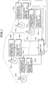
- a vehicle has has four shock absorbers M1a, M1b, M1c and M1d, each having at least two different characteristics of the damping force (soft state and hard state).
- a shock absorber control system according to a preferred embodiment of the present invention has road surface condition detecting units M2a, M2b, M2c and M2d, damping force characteristic alteration units M3a, M3b, M3c and M3d, and a correction unit M4.
- the road surface condition detecting units M2a, M2b, M2c and M2d are provided for the shock absorbers M1a, M1b, M1c and M1d, respectively.
- the road surface condition detecting units M2a, M2b, M2c and M2d respectively detect a roughness of a road surface on which the vehicle is traveling from signals related to the shock absorbers M1a, M1b, M1c and M1d, and respectively generate road surface condition detection values which indicate whether or not the road surface is rough.
- the damping force characteristic alteration units M3a, M3b, M3c and M3d are provided for the shock absorbers M1a, M1b, M1c and M1d, respectively, and compare the road surface condition detection values with respective reference values, and respectively alter the setting of the damping forces of the shock absorbers M1a, M1b, M1c and M1d on the basis of the comparison results.
- the correction unit M4 calculates detection characteristics of the road surface condition detecting units M2a, M2b, M2c and M2d from the respective road surface condition detection values generated and output by these units, and corrects the respective reference values or the road surface condition detection values on the basis of the calculated detection characteristics. With the above arrangement, it becomes possible to alter the setting of the damping force of each of the shock absorbers M1a, M1b, M1c and M1d under an identical alteration condition (level).
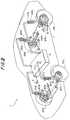
- the vehicle 1 has an apparatus for controlling the setting (characteristic) of the damping force of each shock absorber according to the preferred embodiment of the present invention.
- the vehicle 1 has four variable damping force type shock absorbers 2FL, 2FR, 2RL and 2RR (hereafter simply referred to as shock absorbers).
- the damping force control apparatus has a vehicle speed sensor 3 and an electronic control unit (hereafter simply referred to as an ECU) 4.
- the shock absorbers 2FL, 2FR, 2RL and 2RR respectively have piezoelectric load sensors which sense the damping forces exerted on the shock absorbers 2FL, 2FR, 2RL and 2RR, and piezoelectric actuators for switching the setting of the damping forces between a high level (hard state) and a low level (soft state).
- the shock absorbers 2FL, 2FR, 2RL and 2RR are respectively provided, together with coil springs 8FL, 8FR, 8RL and 8RR, between a vehicle 7 and suspension lower arms 6FL, 6FR, 6RL and 6RR of a left front wheel 5FL, a right front wheel 5FR, a left rear wheel 5RL and a right rear wheel 5RR.
- a detection signal from the vehicle speed sensor 3 is input to the ECU 4, which outputs controls signals to the above-mentioned piezoelectric actuators.
- shock absorbers 2FL, 2FR, 2RL and 2RR A description will now be given of the structures of the shock absorbers 2FL, 2FR, 2RL and 2RR. Since the shock absorbers 2FL, 2FR, 2RL and 2RR have the same structures, only the shock absorber 2FL provided for the left front wheel 5FL will be explained below.
- FIG.3A illustrates the structure of the shock absorber 2FL.
- the shock absorber 2FL has a cylinder 11.
- a main piston 12 engages with an inner wall of the cylinder 11 so that the main piston 12 can slide in the cylinder 11 in the axial directions indicated by arrows A and B.
- the inner area of the cylinder 11 is divided into a first fluid room 13 and a second fluid room 14 by the main piston 12.
- the main piston 12 is connected to one end of a piston rod 15, which has the other end fixed to a shaft 16.
- a lower portion (not shown for the sake of simplicity) of the shaft 11 is connected to the lower arm 6FL for the left front wheel 5FL, and an upper portion (also not shown for the sake of simplicity) of the shaft 11 is connected to the vehicle body 7.
- the main piston 12 has an expansion side fixed orifice 17 and a contraction side fixed orifice 18.
- the fixed orifices 17 and 18 respectively connect the first fluid room 13 and the second fluid room 14 to each other.
- a plate valve 17a which limits the flow of actuating oil to one direction is provided on an outlet port side of the expansion side fixed orifice 17.
- a plate valve 15a which limits the flow of actuating oil to one direction is provided on an outlet port side of the contraction side fixed orifice 18.
- the actuating oil in the first fluid room 13 flows to the second fluid room 14 through the expansion side fixed orifice 17, and the actuating oil in the second fluid room 14 flows to the first fluid room 13 through the contraction side fixed orifice 18.
- the damping force of the shock absorber 2FL is based on the cross section of a passage of the actuating oil, as will be described later.
- the piston rod 15 has a central hollow portion in which a piezoelectric actuator 19FL is provided.
- the piezoelectric actuator 19FL is formed of a member in which electrostriction elements are stacked. More specifically, thin plates formed of piezoelectric ceramics are layered through electrodes. In other words, one electrode is sandwiched between two adjacent third plates.
- a lead 19a provided in a passage extending in the shaft 16 in the axial direction is connected to the electrodes.
- a piston 20 is provided at a position close to a lower end surface of the piezoelectric actuator 19FL. Normally, the piston 20 is urged in the direction A by a leaf spring 20a. The piston 20 is slidable in the central hollow portion of the piston rod in the directions A and B.
- the central hollow portion of the piston rod 15 and a bottom surface of the piston 20 form an oil sealing room 21.
- a column-shaped plunger 22 is slidably provided in a through hole provided in the piston rod 15.
- the through hole extends in the axial direction and has one end which faces a bottom portion of the oil sealing room 21. That is, an upper end of the plunger 22 faces the bottom portion of the oil sealing room 21.
- a lower end of the plunger 22 engages with an upper portion of a spool valve 24, which slidably engages with an engagement hole provided in a housing 23 fixed to the piston rod 15.
- the spool valve 24 is urged in the direction A by a spring 25.
- a ring-shaped groove 24a is formed in a lower portion of the spool valve 24, which has a lowermost portion shaped into a column.
- a sub fluid passage 26 which connects the first fluid room 13 and the second fluid room 14 to each other is provided in the piston rod 15. Normally, the sub fluid passage 26 is interrupted by the lowermost portion of the spool valve 24 urged in the direction A by the spring 25, so that the sub fluid passage 26 is divided into two passage portions.
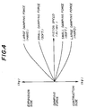
- FIG.4 is a graph showing the relationship between the damping force and a piston speed (m/sec).
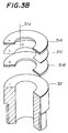
- a piezoelectric load sensor 31FL which senses the magnitude of the damping force exerted on the shock absorber 2FL, is provided on an upper portion of the shaft 16. More specifically, the piezoelectric load sensor 31FL is fixed to the shaft 16 by a nut 32. As shown in FIG.3B, the piezoelectric load sensor 31FL has an electrode 31C sandwiched between two piezoelectric thin plates 31A and 31B formed of piezoelectric ceramics such as PZT. The electrode 31C is connected to the ECU 4 via a lead 31a.
- the ECU 4 has a configuration as shown in FIG.5.
- the ECU 4 has a central processing unit (CPU) 4a, a read only memory (ROM) 4b and a random access memory (RAM) 4c, which form a logic operation circuit.
- the CPU 4a, the ROM 4b and the RAM 4c are connected to an input port (interface) 4e and an output port (interface) 4f via a common bus 4d.
- the ECU 4 has a damping force detection circuit 35, a waveform shaping circuit 36 and a driver circuit 37.
- the damping force detection circuit 35 is provided between the piezoelectric load sensors 31FL, 31FR, 31RL and 31RR and the input port 4e.
- the damping force detection circuit 35 respectively detects, from the charges generated by the piezoelectric load sensors 31FL, 31FR, 31RL and 31RR, the damping forces of the shock absorbers 2FL, 2FR, 2RL and 2RR as well as the rates of change of the damping forces thereof.
- the waveform shaping circuit 36 receives a detection signal generated and output by the vehicle speed sensor 3, and shapes it into an appropriate waveform suitable for digital processing. Output signals of the damping force detection circuit 35 and the waveform shaping circuit 36 are input to the input port 4e.
- the driver circuit 37 is provided between the output port 4f and the piezoelectric load sensors 19FL, 19FR, 19RL and 19RR.
- the driver circuit 37 receives, via the output port 4f, control signals (damping force alteration signals) and generates signals which are actually applied to the piezoelectric actuators 19FL, 19FR, 19RL and 19RR.
- control signals damping force alteration signals
- signals When such signals are applied to the piezoelectric actuators 19FL, 19FR, 19RL and 19RR, they expand, so that the setting of the damping forces of the shock absorbers 2FL, 2FR, 2RL and 2RR are altered to the low level.
- the damping force detection circuit 35 has four detection circuits 41FL, 41FR, 41RL and 41RR provided respectively for the piezoelectric load sensors 31FL, 31FR, 31RL and 31RR. A description will now be given of the detection circuit 41FL. It will be noted that the other detection circuits 41FR, 41RL and 41RR operate in the same way as the detection circuit 41FL.
- the detection circuit 41FL has a resistor R1 connected to the piezoelectric load sensor 31FL in parallel form.
- a change based on the damping force by expansion or contraction of the shock absorber 2FL is developed across the piezoelectric load sensor 31FL.
- a current based on the above charge passes through the resistor R1. That is, a current passes through the resistor R1 each time the damping force is changed and thus a charge is generated in the piezoelectric load sensor 31FL. The amount of this current indicates the damping force change rate.
- the current passing through the resistor R1 is converted into a voltage by the resistor R1. That is, a voltage developed across the resistor R1 indicates the damping force change rate related to the shock absorber 2FL.
- the voltage across the resistor R1 is subjected to a signal processing which will be described below, and applied to an analog-to-digital (A/D) converter 42FL.
- the A/D converter 42FL converts an output signal from the damping force change rate detection circuit 41FL into a digital detection signal indicative of the damping force change rate related to the shock absorber 2FL.
- output signals from the damping force change rate detection circuits 41FR, 41RL and 41RR are applied to A/D converters 42FR, 42RL and 42RR, which generates detection signals which indicate the damping force change rates related to the shock absorbers 2FR, 2RL and 2RR, respectively.
- the voltage developed across the resistor R1 is applied to a radio wave noise elimination filter EMI of the damping force change rate detecting circuit 50 via a resistor R2.
- the noise elimination filter EMI is composed of two coils L1 and L2, and a capacitor C1, and eliminates high-frequency components, such as radio wave noise, from the voltage signal applied thereto.
- a voltage signal obtained by eliminating the high-frequency components is applied to a highpass filter HPF, which has a capacitor C2 and a resistor R3. More specifically, the voltage signal from the noise elimination filter EMI is applied to the capacitor C2, and an offset voltage equal to 2 volts is applied to the resistor R3.
- the highpass filter HPF eliminates low-frequency components having the frequencies equal to or lower than 0.1Hz from the voltage signal from the noise elimination filter EMI. At the same time, the voltage signal from the noise elimination filter EMI is increased by 2 volts.
- An output signal of the highpass filter HPF is applied to a lowpass filter LPF, which has a resistor R4 and a capacitor C3.
- the lowpass filter LPF eliminates high-frequency components having the frequencies equal to or higher than 100Hz from the signal from the highpass filter HPF.
- An output signal of the lowpass filter LPF passes through a buffer circuit formed of an operational amplifier OP1, and then applied to the A/D converter 42FL. The output terminal of the buffer circuit is grounded via a resistor R5.
- a series circuit consisting of diodes D1 and D2 is connected between a high-potential side power source having a voltage of 5 volts and a low-potential side power source having a voltage equal to the ground level.
- the diodes D1 and D2 are provided for protecting the operational amplifier OP1 so that the input voltage applied to the non-inverting input terminal of the operational amplifier OP1 is maintained between 0 volt and 5 volts.
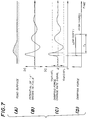
- FIG.7(A) shows a road surface having a projection.
- the voltage developed across the resistor R1 changes on the basis of an expansion/contraction acceleration, as shown in FIG.7(B).
- the voltage shown in FIG.7(B) is processed by the filters EMI, HPF and LPF, and passes through the operational circuit OP1.
- the driver circuit 37 (FIG.5) has a high-voltage generation circuit 47, and charge/discharge circuits 47FL, 47FR, 47RL and 47RR provided respectively for the piezoelectric actuators 19FL, 19FR, 19RL and 19RR.
- the high-voltage generation circuit 45 has a DC/DC converter 45a and a capacitor 45b connected to an output terminal of the DC/DC converter 45.
- the DC/DC converter 45a converts the battery voltage +B into a voltage of 600 volts, which is stored in the capacitor 45b.
- the charge/discharge circuits 47FL, 47FR, 47RL and 47RR receives damping force alteration signals generated and output by the CPU 4a (FIG.5), and charge or discharge the piezoelectric actuators 19FL, 19FR, 19RL and 19RR in response to the respective damping force alteration signals. More specifically, when the damping force alteration signals are maintained at a low level, the charge/discharge circuits 47FL, 47FR, 47RL and 47RR apply a high voltage approximately equal to, for example, 600 volts, so that the piezoelectric actuators 19FL, 19FR, 19RL and 19RR are charged. On the other hand, when the damping force alteration signals are maintained at a high level, the charge/discharge circuits 47FL, 47FR, 47RL and 47RR discharge the piezoelectric actuators 19FL, 19FR, 19RL and 19RR, respectively.
- the charge/discharge circuit 47FL has resistors R7 - R10, diodes D9 and D10, and transistors Tr1 and Tr2.
- the damping force alteration signal which is related to the shock absorber 2FL and generated by the CPU 4a is applied to the base of the transistor Tr1 through the resistor R7.
- the base of the transistor Tr1 is grounded through the resistor R8, and the emitter thereof is grounded.
- a series circuit consisting of the diodes D9 and D10 is connected between the collector and emitter of the transistor Tr1.
- the anode of the diode D9 is grounded, and the cathode of the diode D10 is connected to the collector of the transistor Tr1.
- the high-voltage generation circuit 45 generating the high voltage equal to 600 volts is connected to the collector of the transistor Tr1 and the base of the transistor Tr2 via the resistor R9.
- the high voltage equal to 600 volts is directly applied to the collector of the transistor Tr2.
- the emitter of the transistor Tr2 is connected to the piezoelectric actuator 19FL via the resistor R10, the cathode of the diode D9 and the anode of the diode D10.
- the transistors Tr1 and Tr2 are turned OFF and ON, respectively.
- the high-voltage generation circuit 45 is connected to the piezoelectric actuator 19FL via the transistor Tr2 and the resistor R10, so that the high voltage approximately equal to 600 volts is applied to the piezoelectric actuator 19FL.
- the transistors Tr1 and Tr2 are turned ON and OFF, respectively.
- the high-voltage generation circuit 45 is disconnected from the piezoelectric actuator 19FL, and instead the piezoelectric actuator 19FL is grounded via the resistor R10, the diode D10 and the transistor Tr1, so that the piezoelectric actuator 19FL is discharged.
- the piezoelectric actuators 19FL, 19FR, 19RL and 19RR expand and thus the setting levels of the damping forces of the shock absorbers 2FL, 2FR, 2RL and 2RR decrease when the high voltages approximately equal to 600 volts are respectively applied to the piezoelectric actuators 19FL, 19FR, 19RL and 19RR.
- the piezoelectric actuators 19FL, 19FR, 19RL and 19RR contract and thus the setting levels of the damping forces of the shock absorbers 2FL, 2FR, 2RL and 2RR increase when the piezoelectric actuators 19FL, 19FR, 19RL and 19RR are discharged.
- the damping force alteration signals having the low levels are applied to the charge/discharge circuits 47FL, 47FR, 47RL and 47RR.
- the damping force alteration signals having the high levels are applied to the charge/discharge circuits 47FL, 47FR, 47RL and 47RR.
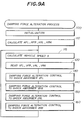
- the CPU 4a carries out an initialization process in which a counter and threshold values for detecting a roughness of a road surface which will be described later are initialized.
- the CPU 4a calculates sensor output correction coefficients KFL, KFR, KRL and KRR, which are used for compensating for differences between the detection characteristics of the piezoelectric load sensors 31FL, 31FR, 31RL and 31RR as well as the detection circuits 41FL, 41FR, 41RL and 41RR.
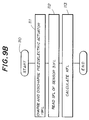
- Steps 111 - 113 shown in FIG.9B show the details of the procedure at step 110.
- the CPU 4a causes the piezoelectric actuator 19FL provided for the left front wheel 5FL to be charged or discharged. More specifically, the CPU 4a outputs the damping force alteration signal maintained at the low level to the driver circuit 37 (FIG.8), so that the high voltage is applied to the piezoelectric actuator 19FL. After that, the CPU 4a changes the damping force alteration signal to the high level, so that the piezoelectric actuator 19FL is discharged and thus contacts.
- the CPU 4a reads an output SFL of the piezoelectric load sensor 31FL through the damping force charge rate alteration circuit 35. That is, the CPU 4a reads the damping force change rate signal indicated by the output SFL of the piezoelectric load sensor 31FL.
- the CPU 4a calculates sensor output correction coefficients KFR, KRL and KRR provided respectively for the wheels 5FR, 5RL and 5RR, and returns to step 115 shown in FIG. 9A.
- a procedure starting from step 115 shown in FIG.9A is repeatedly carried out by the CPU 4a.
- the CPU 4a calculates a current vehicle speed from the detection signal output by the vehicle speed sensor 3 (FIG.5).
- the CPU 4a reads the damping force change rate signals VFL, VFR, VRL and VRR on the basis of the detection signals from the damping force change rate detection circuit 35.
- the CPU 4a separately executes the damping force alteration control for the shock absorbers 2FL, 2FR, 2RL and 2RR, and returns to step 115.
- the CPU 4a executes a procedure as shown in FIG.10, which shows a procedure related to the shock absorber 2FL for the left front wheel 5FL.
- the procedures for the shock absorbers 2FR, 2RL and 2RR are carried out in the same way as the procedure for the shock absorber 2FL.
- step 200 the CPU 4a determines whether or not the vehicle speed obtained at step 115 shown in FIG.9A is greater than zero. In other words, step 200 determines whether or not the vehicle is traveling. When it is determined, at step 200, that the vehicle is not traveling, the CPU 4a executes step 210 at which step, a timer counter CTFL is reset to zero.
- step 200 when it is determined, at step 200, that the vehicle is traveling (S > 0), the CPU 4a executes step 220 at which step the damping force change rate signal VFL which is related to the shock absorber 2FL and which is read at step 120 shown in FIG.9A has become greater than an after-correction upper limit value Vref1KFL, which is obtained by multiplying an upper limit value Vref1FL determined beforehand for the shock absorber 2FL by the sensor output correction coefficient KFL calculated at step 110.
- upper limit values Vref1FR, Vref1RL and Vref1RR are determined beforehand for the shock absorbers 2FR, 2RL and 2RR, respectively.
- upper limit values Vref2FR, Vref2RL and Vref2RR are determined beforehand for the shock absorbers 2FR, 2RL and 2RR, respectively. It will be noted that the upper and lower limit values Vref1FL and Vref2FL are threshold values for detecting a roughness of the road surface, and are set to be standard values.
- the CPU 4a writes, into the time counter CTFL, a soft state holding period Ts during which the setting of the damping force is maintained in the soft state.
- the CPU 4a outputs the damping force alteration signal maintained at the low level to the charge/discharge circuit 47FL, so that the setting of the damping force of the shock absorber 2FL is altered to the low level (soft state).
- the timer counter CTFL is a down counter which counts down the soft state holding period Ts at predetermined intervals until the count value therein becomes zero.
- the damping force change rate signal VFL is continuously maintained in the range between the after-correction upper limit value Vref1KFL and the after-correction lower limit value Vref2KFL during the soft state holding period Ts.
- the above-mentioned preferred embodiment of the present invention uses a set of after-correction upper and lower limit values (Vref1KFL, Vref2KFL), (Vref1KFR, Vref2KFR), (Vref1KRL, Vref2KRL), (Vref1KRR, Vref2KRR) obtained by multiplying the predetermined upper and lower limit values (Vref1FL, Vref2FL), (Vref1FR, Vref2FR), (Vref1RL, Vref2RL), (Vref1RR, Vref2RR) by the sensor output correction coefficients KFL, KFR, KRL and KRR, respectively.
- the sensor output correction coefficients KFL, KFR, KRL and KRR are calculated by expanding and contracting the piezoelectric actuators 19FL, 19FR, 19RL and 19RR immediately after the engine is started and before the damping force alteration control is started and by calculating the ratios MFL/SFL, MFR/SFR, MRL/SRL and MRR/SRR.
- the sensor output correction coefficients KFL, KFR, KRL and KRR are calculated before the damping force alteration control to the shock absorbers 2FL, 2FR, 2RL and 2RR is carried out.
- the sensor output correction coefficient KFL is calculated, as shown in FIG.11, which shows the details of step 110 shown in FIG.9.
- the CPU 4a integrates the absolute values of the damping force change rates of the shock absorbers 2FL, 2FR, 2RL and 2RR (differences between the envelops of the damping force change rate signals VFL, VFR, VRL and VRR and the offset voltage equal to 2 volts) during a predetermined period, and outputs integrated values OFL, OFR, ORL and ORR.
- the sensor output correction coefficients KFR, KRL and KRR can be calculated. Further, it is possible to multiply the sensor output correction value KFL by a deterioration coefficient based on the traveling distance and or the traveling time, so that the damping force alteration control becomes immune to deteriorations with age.
- the aforementioned embodiments of the present invention correct the threshold values used for altering the setting of the damping forces of the shock absorbers 2FL, 2FR, 2RL and 2RR.
- a shock absorber control system having shock absorbers (M1a, M1b, M1c, M1d) provided respectively between wheels of a vehicle and a body thereof includes road surface condition detecting units (M2a, M2b, M2c, M2d) provided for the respective shock absorbers, and damping force characteristic alteration units (M3a, M3b, M3c, M3d) provided for the respective shock absorbers.
- the shock absorber control system also includes a correction unit (M4) for separately generating signals indicative of detection characteristics of the road surface condition detecting units provided for the respective shock absorbers on the basis of road surface condition detection signals generated by the road surface condition detecting units and for separately correcting either reference values used for determining whether or not the road surface is rough by the damping force characteristic alteration units or the road surface condition detection signals on the basis of the detection characteristics of the road surface condition detecting units provided for the respective shock absorbers.
- M4 correction unit for separately generating signals indicative of detection characteristics of the road surface condition detecting units provided for the respective shock absorbers on the basis of road surface condition detection signals generated by the road surface condition detecting units and for separately correcting either reference values used for determining whether or not the road surface is rough by the damping force characteristic alteration units or the road surface condition detection signals on the basis of the detection characteristics of the road surface condition detecting units provided for the respective shock absorbers.
Landscapes
- Engineering & Computer Science (AREA)
- Mechanical Engineering (AREA)
- Vehicle Body Suspensions (AREA)
- Fluid-Damping Devices (AREA)
Claims (11)
- Un système de commande d'amortisseur, pour la commande d'amortisseurs (M1a, M1b, M1c, M1d), monté entre les roues respectives d'un véhicule et la caisse du véhicule, chacun desdits amortisseurs ayant au moins deux caractéristiques de force d'amortissement différentes, ledit système de commande d'amortisseur comprenant :des moyens de détection d'état de surface de la route (M2a, M2b, M2c, M2d), prévus pour les amortisseurs respectifs, afin de détecter les inégalités de la surface de la route sur laquelle le véhicule se déplace et pour générer des signaux de détection d'état de surface de route qui sont liés aux amortisseurs respectifs et qui indiquent si la surface de la route est inégale ou non,des moyens de modification des caractéristiques de force d'amortissement (M3a, M3b, M3c, M3d), prévus pour les amortisseurs respectifs, afin de comparer lesdits signaux de détection d'état de surface de route à des valeurs de référence prévues pour les amortisseurs respectifs et pour modifier séparément le réglage des forces d'amortissement desdits amortisseurs, sur la base des résultats de comparaison obtenus pour les amortisseurs respectifs,caractérisé par
des moyens de correction (M4), couplés auxdits moyens de détection d'état de surface de route et auxdits moyens de modification de caractéristiques de force d'amortissement prévus pour les amortisseurs respectifs, afin de générer séparément des signaux indicatifs des caractéristiques de détection desdits moyens de détection d'état de surface de route pour les amortisseurs respectifs, sur la base desdits signaux de détection d'état de surface de route et pour corriger séparément lesdites valeurs de référence sur la base desdites caractéristiques de détection desdits moyens de détection d'état de surface de route fournies pour les amortisseurs respectifs en générant des coefficients de correction liés aux valeurs de référence respectives prévues pour lesdits amortisseurs et en multipliant lesdites valeurs de référence par lesdits coefficients de correction, de telle manière que lesdites valeurs de référence soient corrigées. - Un système de commande d'amortisseur pour la commande d'amortisseurs (M1a, M1b, M1c, M1d), prévus entre les roues respectives d'un véhicule et sa caisse, chacun desdits amortisseurs ayant au moins deux caractéristiques de force d'amortissement différentes, ledit système de commande d'amortisseur comprenant :des moyens de détection d'état de surface de la route (M2a, M2b, M2c M2d), prévus pour les amortisseurs respectifs afin de détecter les inégalités de la surface de la route sur laquelle le véhicule se déplace et pour générer des signaux de détection d'état de surface de route qui sont liés au amortisseurs respectifs et qui indiquent si la surface de la route est inégale ou non,des moyens de modification des caractéristiques de force d'amortissement (M3a, M3b, M3c, M3d), prévus pour les amortisseurs respectifs, afin de comparer lesdits signaux de détection d'état de surface de route à des valeurs de référence prévues pour les amortisseurs respectifs et pour modifier séparément le réglage des forces d'amortissement desdits amortisseurs sur la base des résultats de comparaison obtenus pour les amortisseurs respectifs,caractérisé par
des moyens de correction (M4), couplés auxdits moyens de détection de surface de route et auxdits moyens de modification de caractéristiques de force d'amortissement prévus pour les amortisseurs respectifs, afin de générer séparément des signaux indicatifs des caractéristiques de détection desdits moyens de détection d'état de surface de route pour les amortisseurs respectifs sur la base desdits signaux de détection d'état de surface de route et pour corriger séparément lesdits signaux de détection de surface de route sur la base desdites caractéristiques de détection desdits moyens de détection de surface de route fournis pour les amortisseurs respectifs. - Un système de commande d'amortisseur selon la revendication 1, caractérisé en ce que :
lesdits moyens de détection d'état de surface de route prévus pour les amortisseurs respectifs comprennent des moyens (35), destinés à générer des signaux de taux de variation de force d'amortissement représentatifs des taux de variation des forces d'amortissement desdits amortisseurs, lesdits signaux de taux de variation de force d'amortissement correspondant auxdits signaux de détection d'état de surface de route ; et en ce que
lesdits moyens de correction comprennent des moyens de génération de coefficient de correction (4a, 113, 303) couplés auxdits moyens de détection d'état de surface de route prévus pour les amortisseurs respectifs afin de générer lesdits coefficients de correction liés aux valeurs de référence respectives prévues pour lesdits amortisseurs, et pour multiplier lesdites valeurs de référence par lesdits coefficients de correction, de manière à corriger lesdites valeurs de référence. - Un système de commande d'amortisseur selon la revendication 3, caractérise en ce que :
lesdits moyens de génération de coefficient de correction comprennent des moyens de génération de rapport (113), destinés à générer des rapports entre une valeur standard prédéterminée et lesdits signaux de taux de variation de la force d'amortissement générés pour les amortisseurs respectifs ; et en ce que
lesdits rapports entre la valeur standard prédéterminée et lesdits signaux de taux de variation de force d'amortissement correspondent auxdits coefficients de correction respectivement liés auxdites valeurs de référence prévues pour les amortisseurs respectifs. - Un système de commande d'amortisseur selon la revendication 3, caractérisé en ce que :
lesdites valeurs de référence prévues pour les amortisseurs respectifs comprennent des valeurs limites supérieures et des valeurs limites inférieures, prévues pour les amortisseurs respectifs ;
lesdits moyens de génération de coefficient de correction comprennent des moyens de multiplication (220, 230), conçus pour multiplier lesdites valeurs limites supérieures par lesdits coefficients de correction, de manière à générer des valeurs limites supérieures après correction, prévues pour les amortisseurs respectifs, et pour multiplier lesdites valeurs limites inférieures par lesdits coefficients de correction pour, de cette manière, générer des valeurs limites inférieures après correction, prévues pour les amortisseurs respectifs ; et en ce que
lesdits moyens de modification des caractéristiques de force d'amortissement comprennent des moyens de détermination (220, 230), prévus pour les amortisseurs respectifs, afin de déterminer si lesdits signaux de taux de variation de force d'amortissement sont ou non hors des plages respectivement définies par lesdites valeurs limites supérieures après correction et lesdites valeurs limites inférieures après correction, et pour modifier séparément les réglages des forces d'amortissement des amortisseurs respectifs, depuis un état dur vers un état souple ou non, lorsqu'il est déterminé que lesdits signaux de taux de variation de force d'amortissement sont hors desdites plages, ledit état dur et ledit état souple correspondant auxdites au moins deux caractéristiques de force d'amortissement de chacun desdits amortisseurs. - Un système de commande d'amortisseur selon la revendication 3, caractérisé en ce que lesdits moyens de génération de coefficient de correction comprennent :des moyens d'intégration (301), conçus pour intégrer séparément lesdits signaux de taux de variation de force d'amortissement liés auxdits amortisseurs respectifs, pendant une période de temps prédéterminée, et pour générer des valeurs intégrées prévues pour les amortisseurs respectifs ;des moyens de génération de valeur moyenne (302) destinés à générer une valeur moyenne desdites valeurs intégrées en divisant la somme desdites valeurs intégrées par le nombre desdites roues ; etdes moyens de génération de rapport (303) conçus pour générer des rapports entre lesdites valeurs moyennes desdites valeurs intégrées et lesdites valeurs intégrées générées pour les amortisseurs respectifs,dans lequel lesdits rapports entre ladite valeur moyenne et lesdites valeurs intégrées correspondent auxdits coefficients de correction liés auxdites valeurs de référence fournies pour les amortisseurs respectifs.
- Un système de commande d'amortisseur selon la revendication 3, caractérisé en ce que lesdits moyens de génération de coefficient de correction comprennent :des moyens d'intégration (301) destinés à intégrer séparément lesdits signaux de taux de variation de force d'amortissement liés auxdits amortisseurs respectifs pendant une période de temps prédéterminée et pour générer des valeurs intégrées prévues pour les amortisseurs respectifs ; etdes moyens de génération de rapport (302), destinés à générer des rapports entre les valeurs prédéterminées définies pour les amortisseurs respectifs et lesdites valeurs intégrées générées pour les amortisseurs respectifs, etdans lequel lesdits rapports, entre lesdites valeurs prédéterminées et lesdites valeurs intégrées, correspondent auxdits coefficients de correction liés auxdites valeurs de référence prévues pour les amortisseurs respectifs.
- Un système de commande d'amortisseur selon la revendication 1 ou 2, caractérisé en ce que :
lesdits moyens de détection d'état de surface de route prévus pour les amortisseurs respectifs comprennent des moyens (35) destinés à générer des signaux de taux de variation de force d'amortissement représentatifs des taux de fluctuation des forces d'amortissement desdits amortisseurs, lesdits signaux de taux de fluctuation de force d'amortissement correspondant auxdits signaux de détection d'état de surface de route ; et
lesdits moyens de correction comprennent des moyens de génération de coefficient de correction (4a, 113), prévus pour les amortisseurs respectifs et couplés auxdits moyens de détection d'état de surface de route, pour générer des coefficients de correction liés respectivement auxdites valeurs de référence fournies pour lesdits amortisseurs respectifs et pour multiplier lesdits signaux de détection d'état de surface de route par lesdits coefficients de correction, de telle manière que lesdits signaux de détection d'état de surface de route soient corrigés. - Un système de commande d'amortisseur selon la revendication 1 ou 2, caractérisé en ce que lesdits moyens de détection d'état de surface de route (M2a, M2b, M2c M2d) prévus pour les amortisseurs respectifs comprennent des capteurs piézoélectriques de charge (31FL, 31FR, 31RL, 31RR), générant lesdits signaux de taux de variation de force d'amortissement.
- Un système de commande d'amortisseur selon la revendication 5, caractérisé en ce que lesdits moyens de modification de caractéristiques de force d'amortissement (M3a, M3b, M3c, M3d) prévus pour les amortisseurs respectifs comprennent des moyens de maintien à l'état souple (260) destinés à maintenir séparément lesdits amortisseurs dans ledit état souple pendant une période de temps prédéterminée de maintien à l'état souple, pendant laquelle les signaux de taux de variation de force d'amortissement, liés auxdits amortisseurs respectifs, sont conservés de façon continue dans lesdites plages, après que lesdits amortisseurs respectifs ont été réglés audit état souple, depuis ledit état dur.
- Un système de commande d'amortisseur selon la revendication 10, caractérisé en ce que lesdits moyens de modification de caractéristiques de force d'amortissement (M3a, M3b, M3c, M3d), prévus pour les amortisseurs respectifs, comprennent des moyens (270) destinés à modifier séparément le réglage des forces d'amortissement desdits amortisseurs depuis ledit état souple jusqu'audit état dur, après l'écoulement de ladite période de temps de maintien à l'état souple.
Applications Claiming Priority (2)
| Application Number | Priority Date | Filing Date | Title |
|---|---|---|---|
| JP2036847A JP3041870B2 (ja) | 1990-02-16 | 1990-02-16 | ショックアブソーバ制御装置 |
| JP36847/90 | 1990-02-16 |
Publications (3)
| Publication Number | Publication Date |
|---|---|
| EP0442530A2 EP0442530A2 (fr) | 1991-08-21 |
| EP0442530A3 EP0442530A3 (en) | 1992-11-19 |
| EP0442530B1 true EP0442530B1 (fr) | 1997-05-07 |
Family
ID=12481156
Family Applications (1)
| Application Number | Title | Priority Date | Filing Date |
|---|---|---|---|
| EP91102201A Expired - Lifetime EP0442530B1 (fr) | 1990-02-16 | 1991-02-15 | Système de commande d'amortisseurs |
Country Status (4)
| Country | Link |
|---|---|
| US (1) | US5134566A (fr) |
| EP (1) | EP0442530B1 (fr) |
| JP (1) | JP3041870B2 (fr) |
| DE (1) | DE69125961T2 (fr) |
Families Citing this family (15)
| Publication number | Priority date | Publication date | Assignee | Title |
|---|---|---|---|---|
| GB2239506B (en) * | 1989-12-08 | 1993-08-25 | Toyota Motor Co Ltd | Suspension control system |
| KR970011089B1 (ko) * | 1992-02-14 | 1997-07-07 | 미쯔비시 지도샤 고교 가부시끼가이샤 | 노면상태의 식별방법 및 써스펜션의 제어 장치 |
| US5497325A (en) * | 1992-08-31 | 1996-03-05 | Fuji Jukogyo Kabushiki Kaisha | Suspension control system for a vehicle |
| US5432700A (en) * | 1992-12-21 | 1995-07-11 | Ford Motor Company | Adaptive active vehicle suspension system |
| KR100726600B1 (ko) * | 2003-03-14 | 2007-06-11 | 주식회사 만도 | 전자제어 현가장치와 그 제어 방법 |
| US7913822B2 (en) * | 2006-12-22 | 2011-03-29 | Chrysler Group Llc | Ride height sensing shock damper |
| US8428819B2 (en) * | 2007-08-31 | 2013-04-23 | GM Global Technology Operations LLC | Suspension system with optimized damper response for wide range of events |
| JP5307460B2 (ja) * | 2008-07-03 | 2013-10-02 | ヤマハ発動機株式会社 | 懸架装置の制御システムおよび車両 |
| BR112012030656A2 (pt) | 2010-06-03 | 2016-08-16 | Polaris Inc | veículo, e, método de controle do afogador eletrônico para um veículo |
| US9241850B2 (en) | 2011-09-02 | 2016-01-26 | Ferno-Washington, Inc. | Litter support assembly for medical care units having a shock load absorber and methods of their use |
| MX2017005022A (es) * | 2014-10-31 | 2017-06-29 | Polaris Inc | Sistema y metodo para controlar un vehiculo. |
| DE102015204993B4 (de) * | 2015-03-19 | 2021-11-18 | Zf Friedrichshafen Ag | Kurzbauende Dämpfventileinrichtung |
| US10406884B2 (en) | 2017-06-09 | 2019-09-10 | Polaris Industries Inc. | Adjustable vehicle suspension system |
| US10987987B2 (en) | 2018-11-21 | 2021-04-27 | Polaris Industries Inc. | Vehicle having adjustable compression and rebound damping |
| CA3173047A1 (fr) | 2020-05-20 | 2021-11-25 | Michael A. Hedlund | Systemes et procedes de suspensions reglables pour vehicules recreatifs hors route |
Family Cites Families (9)
| Publication number | Priority date | Publication date | Assignee | Title |
|---|---|---|---|---|
| US4770438A (en) * | 1984-01-20 | 1988-09-13 | Nissan Motor Co., Ltd. | Automotive suspension control system with road-condition-dependent damping characteristics |
| US4729459A (en) * | 1984-10-01 | 1988-03-08 | Nippon Soken, Inc. | Adjustable damping force type shock absorber |
| DE3437799A1 (de) * | 1984-10-16 | 1986-04-24 | August Bilstein GmbH & Co KG, 5828 Ennepetal | Verfahren zur ueberwachung und beeinflussung von stossdaempfern |
| US4837727A (en) * | 1985-03-04 | 1989-06-06 | Nippon Soken, Inc. | Road surface detecting device for vehicle |
| JPS62152914A (ja) * | 1985-12-26 | 1987-07-07 | Nippon Soken Inc | 走行路面状態検出装置 |
| JPH0829654B2 (ja) * | 1986-12-19 | 1996-03-27 | 日産自動車株式会社 | 車高調整装置 |
| JP2516780B2 (ja) * | 1987-04-17 | 1996-07-24 | 本田技研工業株式会社 | 車両走行時の悪路検出装置 |
| JPH0238174A (ja) * | 1988-07-29 | 1990-02-07 | Aisin Seiki Co Ltd | 路面状態検出装置および車上制御装置 |
| DE68915442T2 (de) * | 1989-08-03 | 1995-01-05 | Nippon Denso Co | Kontrollsystem für die Dämpfkraft von Stossdämpfern. |
-
1990
- 1990-02-16 JP JP2036847A patent/JP3041870B2/ja not_active Expired - Lifetime
-
1991
- 1991-02-15 DE DE69125961T patent/DE69125961T2/de not_active Expired - Lifetime
- 1991-02-15 EP EP91102201A patent/EP0442530B1/fr not_active Expired - Lifetime
- 1991-02-19 US US07/656,726 patent/US5134566A/en not_active Expired - Lifetime
Also Published As
| Publication number | Publication date |
|---|---|
| DE69125961T2 (de) | 1997-11-27 |
| US5134566A (en) | 1992-07-28 |
| JP3041870B2 (ja) | 2000-05-15 |
| JPH03239617A (ja) | 1991-10-25 |
| EP0442530A3 (en) | 1992-11-19 |
| DE69125961D1 (de) | 1997-06-12 |
| EP0442530A2 (fr) | 1991-08-21 |
Similar Documents
| Publication | Publication Date | Title |
|---|---|---|
| EP0442530B1 (fr) | Système de commande d'amortisseurs | |
| EP0446637B1 (fr) | Appareil de contrÔle de la force d'amortissement d'un amortisseur de chocs | |
| US5361209A (en) | Suspension control system having damping coefficient discretely varied responsive to road conditions | |
| EP0417695B1 (fr) | Système de contrÔle de suspension | |
| EP0417702B1 (fr) | Système de contrÔle de suspension | |
| EP0411193B1 (fr) | Système pour contrôler la force d'amortissement des amortisseurs de choc | |
| EP0397105B1 (fr) | Système de réglage de suspension | |
| US5142477A (en) | Suspension control system | |
| JP2634054B2 (ja) | ショックアブソーバの減衰力制御装置 | |
| JP2619902B2 (ja) | ショックアブソーバの減衰力制御装置 | |
| JP2724756B2 (ja) | サスペンション制御装置 | |
| JP2853394B2 (ja) | サスペンション制御装置 | |
| JP2576652B2 (ja) | サスペンション制御装置 | |
| JP2576650B2 (ja) | サスペンション制御装置 | |
| JP2754809B2 (ja) | サスペンション制御装置 | |
| JP2724755B2 (ja) | サスペンション制御装置 | |
| JPH03253416A (ja) | ショックアブソーバ制御装置 | |
| JP2724754B2 (ja) | サスペンション制御装置 | |
| JP2580818B2 (ja) | サスペンション制御装置 | |
| JPH01202512A (ja) | ショックアブソーバの減衰力検出装置 | |
| JPH03178820A (ja) | サスペンション制御装置 | |
| JP2576649B2 (ja) | サスペンション制御装置 | |
| JP2576651B2 (ja) | サスペンション制御装置 | |
| JPH03200415A (ja) | サスペンション制御装置 | |
| JPH03189437A (ja) | ショックアブソーバ制御装置 |
Legal Events
| Date | Code | Title | Description |
|---|---|---|---|
| PUAI | Public reference made under article 153(3) epc to a published international application that has entered the european phase |
Free format text: ORIGINAL CODE: 0009012 |
|
| 17P | Request for examination filed |
Effective date: 19910215 |
|
| AK | Designated contracting states |
Kind code of ref document: A2 Designated state(s): DE FR GB |
|
| PUAL | Search report despatched |
Free format text: ORIGINAL CODE: 0009013 |
|
| AK | Designated contracting states |
Kind code of ref document: A3 Designated state(s): DE FR GB |
|
| 17Q | First examination report despatched |
Effective date: 19950920 |
|
| GRAG | Despatch of communication of intention to grant |
Free format text: ORIGINAL CODE: EPIDOS AGRA |
|
| GRAH | Despatch of communication of intention to grant a patent |
Free format text: ORIGINAL CODE: EPIDOS IGRA |
|
| GRAH | Despatch of communication of intention to grant a patent |
Free format text: ORIGINAL CODE: EPIDOS IGRA |
|
| GRAA | (expected) grant |
Free format text: ORIGINAL CODE: 0009210 |
|
| AK | Designated contracting states |
Kind code of ref document: B1 Designated state(s): DE FR GB |
|
| REF | Corresponds to: |
Ref document number: 69125961 Country of ref document: DE Date of ref document: 19970612 |
|
| ET | Fr: translation filed | ||
| PLBE | No opposition filed within time limit |
Free format text: ORIGINAL CODE: 0009261 |
|
| STAA | Information on the status of an ep patent application or granted ep patent |
Free format text: STATUS: NO OPPOSITION FILED WITHIN TIME LIMIT |
|
| 26N | No opposition filed | ||
| REG | Reference to a national code |
Ref country code: GB Ref legal event code: 746 Effective date: 19991109 |
|
| REG | Reference to a national code |
Ref country code: FR Ref legal event code: D6 |
|
| REG | Reference to a national code |
Ref country code: GB Ref legal event code: IF02 |
|
| PGFP | Annual fee paid to national office [announced via postgrant information from national office to epo] |
Ref country code: FR Payment date: 20100223 Year of fee payment: 20 |
|
| PGFP | Annual fee paid to national office [announced via postgrant information from national office to epo] |
Ref country code: DE Payment date: 20100226 Year of fee payment: 20 Ref country code: GB Payment date: 20100202 Year of fee payment: 20 |
|
| REG | Reference to a national code |
Ref country code: DE Ref legal event code: R071 Ref document number: 69125961 Country of ref document: DE |
|
| REG | Reference to a national code |
Ref country code: GB Ref legal event code: PE20 Expiry date: 20110214 |
|
| PG25 | Lapsed in a contracting state [announced via postgrant information from national office to epo] |
Ref country code: GB Free format text: LAPSE BECAUSE OF EXPIRATION OF PROTECTION Effective date: 20110214 |
|
| PG25 | Lapsed in a contracting state [announced via postgrant information from national office to epo] |
Ref country code: DE Free format text: LAPSE BECAUSE OF EXPIRATION OF PROTECTION Effective date: 20110215 |