EP0442467B1 - Structure d'installation pour pupitre de transaction - Google Patents
Structure d'installation pour pupitre de transaction Download PDFInfo
- Publication number
- EP0442467B1 EP0442467B1 EP91102012A EP91102012A EP0442467B1 EP 0442467 B1 EP0442467 B1 EP 0442467B1 EP 91102012 A EP91102012 A EP 91102012A EP 91102012 A EP91102012 A EP 91102012A EP 0442467 B1 EP0442467 B1 EP 0442467B1
- Authority
- EP
- European Patent Office
- Prior art keywords
- dealing board
- control panel
- top plate
- fixture
- case
- Prior art date
- Legal status (The legal status is an assumption and is not a legal conclusion. Google has not performed a legal analysis and makes no representation as to the accuracy of the status listed.)
- Expired - Lifetime
Links
Images

Classifications
-
- H—ELECTRICITY
- H04—ELECTRIC COMMUNICATION TECHNIQUE
- H04M—TELEPHONIC COMMUNICATION
- H04M1/00—Substation equipment, e.g. for use by subscribers
- H04M1/02—Constructional features of telephone sets
- H04M1/23—Construction or mounting of dials or of equivalent devices; Means for facilitating the use thereof
-
- A—HUMAN NECESSITIES
- A47—FURNITURE; DOMESTIC ARTICLES OR APPLIANCES; COFFEE MILLS; SPICE MILLS; SUCTION CLEANERS IN GENERAL
- A47B—TABLES; DESKS; OFFICE FURNITURE; CABINETS; DRAWERS; GENERAL DETAILS OF FURNITURE
- A47B21/00—Tables or desks for office equipment, e.g. typewriters, keyboards
-
- H—ELECTRICITY
- H04—ELECTRIC COMMUNICATION TECHNIQUE
- H04M—TELEPHONIC COMMUNICATION
- H04M1/00—Substation equipment, e.g. for use by subscribers
- H04M1/02—Constructional features of telephone sets
- H04M1/0289—Telephone sets for operators
-
- A—HUMAN NECESSITIES
- A47—FURNITURE; DOMESTIC ARTICLES OR APPLIANCES; COFFEE MILLS; SPICE MILLS; SUCTION CLEANERS IN GENERAL
- A47B—TABLES; DESKS; OFFICE FURNITURE; CABINETS; DRAWERS; GENERAL DETAILS OF FURNITURE
- A47B2200/00—General construction of tables or desks
- A47B2200/0066—Workstations
- A47B2200/0078—Control consoles or desks
Definitions
- the invention relates to an installing structure for a dealing board as indicated in the precharacterizing part of claim 1.
- JP-A-60084623 dealing board or keyboard is provided at a computer operation desk in which a board for a display is fixed to its top end to mount and support the display thereupon.
- One side part of the keyboard is sandwiched between top parts of leg members of the operation desk, whereas the other end part of the keyboard is supported rotatably around a fixed knob as a fulcrum.
- a fixed knob as a fulcrum.
- a similar device is disclosed in DE-A-37 36 891 in which a display apparatus can be adjusted to vary its tilting angle with respect to an operation desk or keyboard.
- the surface area between the front edge of the operation desk and the display apparatus is always independent from the location and/or the tilting angle of the display apparatus.
- the dealing board is of a box type, it is possible to improve the workability to assemble the dealing board.
- the box-like case of the dealing board is slanted rearwardly to the top plate of the desk, the user of the dealing board can prevent its knee from hitting the dealing board.
- the length of the front fixture, the angle in which the front fixture is secured to the top plate, and the length of the rear fixture, the angle in which the L-shape portion is bent into L-shape are adjustable before inserting of the dealing board through the open portion, it is possible to adjust the angle of the control panel.
- the print substrate and the control panel are disposed in parallel with the bottom face of the case and the case is installed slantly. Due to this the print substrate is slanted so that heat stream generated from the various electronic parts flows along the print substrate so as to radiate effectively the heat.
- the dealing board consists of a main body 20, a desk 21, a display 22 displaying economy information, a hand-set 23, and a microphone 24.
- the dealing board main body 20 has a box-like case 25, as shown in Fig 2, and the case 25 has a control panel 25a fixed to the topface of the case.
- a bottom face 25h of the case 25 is in parallel with the control panel 25a and the front face 25f and the rear face 25g of the case 25 is at a right angle to the control panel 25a.
- the upper print substrate 27 has a function button 29 exposed from the control panel 25a, as well as a spacer 30 is placed between respective print substrates 27 and 28. These print substrates 27 and 28 are fixed on the rear face of the control panel 25a so as to be in parallel to each other. A pair of connectors 31a and 31b joins electrically the upper print substrate 27 to the lower one 28.
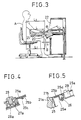
- the function button 29 installed on the upper print substrate 27 has a conductive contact rubber 29a (see Fig 4) at its lower end. Pushing down the function button 29 makes the conductive contact rubber 29a contact the contact 27a formed on the print substrate 27 so as to carry out ON-OFF operation of the circuit.
- the lower print substrate 44 is installed in the bottom space so as to be in parallel with the bottom face 25h of the case 25 through a set of spacers 35. While, the upper print substrate 34 is placed above the lower print substrate 44 in parallel with the print substrate 44 through a set of other spaces 36.
- the other upper or top print substrate 33 is connected to the upper print substrate 34 securely by connectors 45a and 45b. Both the print substrates 33 and 44 are electrically connected to each other by a system of the connector 33a, a signal cable 38a, and the other connector 34a.
- top plate 21a of the desk 21 on which the dealing board main body 20 is mounted has an open portion 21b open a little larger than the area of the dealing board main body 20.
- fixtures 40 and 41 are secured on the lower face of the open portion 21b.
- the fixture 40 installed at the front side of the open portion 21b is longer than that at the rear side of the open portion 21b. Both upper end portions of the fixtures 40 and 41 are secured to the lower face of the top plate 21a by small screws 42.
- the lower portion of the front fixture 40 is rearward slanted and has a lowest L-shape end portion or engagement portion 40a.
- the other rear fixture 41 has a main portion extending in a right angle to the top plate 21a and a top end portion extending from the main portion at a right angle and being secured to a bottom face of the top plate 21 by a small screw 42 as described above.
- the fixture 41 has a bottom or lowest engagement portion 41a extending slantly and downward and an angle adjusting screw 43 is inserted from the below through the lowest engagement portion 41a.
- the bottom face 25h of the case 25 of the dealing board main body 20 inserted from above through the open portion 21b of the desk 21 is supported from the bottom by a front end of the angle adjusting screw 43 and the engagement portion 40a of the fixture 40 so as to slant to the front the control panel 25a relative to the upper face of the top plate 21a of the desk 21.
- the fixing angle of the front fixture 40 is set so as to make the slanting angle ⁇ of the control panel 25a about 20° degree.
- a slanting distance L 1 of the bottom face of the dealing board main body 20 becomes about 68 mm. The distance is sufficient to general users, so that even the length L of the top plate is made short, the knee B of the user A hardly hit the main body 20 resulting in a small size of the desk 21.
- print substrates 33, 34, and 44 are fixed in the bottom space of the main body 20 in parallel with the top face of the control panel and the case 25 is installed slantly, these print substrates 33, 34, and 44 are slanted, so that heat stream 48 shown by an arrow in Fig 2 flows along these print substrates 33, 34, and 34 effectively radiating heat generated from the various electronic parts mounted thereon.
- the engagement piece 25c and the fixing piece 25d are secured to the control panel 25a through for example a welding method, however they may be formed by a molding process of resin.
- the control panel 25a, the case 25, and the fixing piece 25e at the case side may be molded.
- the front and the rear walls 25f and 25g of the case 25 are formed so as to be at a right angle to the plane of the control panel 25a, however it is not necessary to form these walls and right and left walls (not shown) of the case 25 at a right angle to the control panel 25a on condition that at least the bottom face 25h is in parallel to the control panel 25a.
- These walls may be arranged in a shape of diamond seeing from right or left side of the case 25.
Landscapes
- Engineering & Computer Science (AREA)
- Signal Processing (AREA)
- Casings For Electric Apparatus (AREA)
- Telephone Set Structure (AREA)
- Electrophotography Configuration And Component (AREA)
- Push-Button Switches (AREA)
- Input From Keyboards Or The Like (AREA)
Claims (3)
- Structure d'installation pour pupitre de transaction (20) comportant un casier en forme de boîte (25) et un panneau de commande (25a) fixé sur la face supérieure du casier (25), le pupitre de transaction (20) étant installé dans un plateau supérieur (21a) d'un bureau (21) ; caractérisée en ce quea) le plateau supérieur (21a) du bureau (21) comporte une partie ouverte (21b) dans laquelle est installé le pupitre de transaction (20),b) le plateau supérieur (21a) est pourvu d'un organe de fixation arrière (41) attaché à angle droit par rapport à la face inférieure du plateau supérieur (21a) sur le côté arrière de la partie ouverte (21b) et possède une partie de prise (41a) qui s'étend obliquement vers le bas sur la partie d'extrémité inférieure de l'organe de fixation arrière (41), et
un organe de fixation avant (40) est attaché à la face inférieure du plateau supérieur (21a) sur le côté avant de la partie ouverte (21b) de manière à partir en oblique vers l'arrière et est plus long que l'organe de fixation arrière (41) et possède une partie de prise en forme de L (40a) recourbée en forme de L sur la partie d'extrémité inférieure de l'organe de fixation avant (40), etc) le panneau de commande (25a) du pupitre de transaction (20) est orienté obliquement vers l'arrière par rapport au plateau supérieur (21a), de sorte que la face inférieure (25h) et la face avant (25f) du pupitre de transaction (20) puissent être supportées par l'organe de fixation avant (40) et que la face inférieure (25h) et la face arrière (25g) du pupitre de transaction (20) puissent être supportées par l'organe de fixation arrière (41). - Structure d'installation pour pupitre de transaction (20) selon la revendication 1, caractérisée en ce que
la partie de prise (41a) de l'organe de fixation arrière (41) est pourvue d'un trou de vis devant être vissé à l'aide d'une vis (43), de sorte que la face inférieure (25h) du pupitre de transaction (20) puisse être poussée vers le haut par la partie supérieure de la vis (43) vissée dans le trou de vis. - Structure d'installation pour pupitre de transaction (20) selon la revendication 1 ou 2, caractérisée en ce queledit panneau de commande (25a) est pourvu d'une pluralité de touches de fonction (29) et d'un substrat d'impression par contact (27) possédant une pluralité de contacts (27a) correspondant à chacune des touches de fonction (29), etau moins un substrat d'impression (33, 34) qui, électriquement connecté au substrat d'impression par contact (27), est disposé sous le panneau de commande (25a),dans laquelle le panneau de commande (25a) et le substrat d'impression (33, 34) sont disposés parallèlement à la face inférieure (25h) du casier (25).
Priority Applications (2)
| Application Number | Priority Date | Filing Date | Title |
|---|---|---|---|
| EP96100181A EP0713314B1 (fr) | 1990-02-15 | 1991-02-13 | Pupitre de transaction |
| EP96100176A EP0712224B1 (fr) | 1990-02-15 | 1991-02-13 | Pupitre de transaction |
Applications Claiming Priority (10)
| Application Number | Priority Date | Filing Date | Title |
|---|---|---|---|
| JP2032456A JP2711925B2 (ja) | 1990-02-15 | 1990-02-15 | ディーリングボード操作部のパネルユニット |
| JP32455/90 | 1990-02-15 | ||
| JP2032455A JP2623356B2 (ja) | 1990-02-15 | 1990-02-15 | ディーリングボードの取付構造 |
| JP32456/90 | 1990-02-15 | ||
| JP2032454A JPH03237844A (ja) | 1990-02-15 | 1990-02-15 | ディーリングボード |
| JP32454/90 | 1990-02-15 | ||
| JP166834/90 | 1990-06-27 | ||
| JP2166834A JP2572295B2 (ja) | 1990-06-27 | 1990-06-27 | ディーリングボード |
| JP2166835A JPH0457184A (ja) | 1990-06-27 | 1990-06-27 | ディーリングボードのカバー構造 |
| JP166835/90 | 1990-06-27 |
Related Child Applications (4)
| Application Number | Title | Priority Date | Filing Date |
|---|---|---|---|
| EP96100181A Division EP0713314B1 (fr) | 1990-02-15 | 1991-02-13 | Pupitre de transaction |
| EP96100176A Division EP0712224B1 (fr) | 1990-02-15 | 1991-02-13 | Pupitre de transaction |
| EP96100176.5 Division-Into | 1991-02-13 | ||
| EP96100181.5 Division-Into | 1991-02-13 |
Publications (3)
| Publication Number | Publication Date |
|---|---|
| EP0442467A2 EP0442467A2 (fr) | 1991-08-21 |
| EP0442467A3 EP0442467A3 (en) | 1993-07-14 |
| EP0442467B1 true EP0442467B1 (fr) | 1997-10-29 |
Family
ID=27521416
Family Applications (3)
| Application Number | Title | Priority Date | Filing Date |
|---|---|---|---|
| EP91102012A Expired - Lifetime EP0442467B1 (fr) | 1990-02-15 | 1991-02-13 | Structure d'installation pour pupitre de transaction |
| EP96100176A Expired - Lifetime EP0712224B1 (fr) | 1990-02-15 | 1991-02-13 | Pupitre de transaction |
| EP96100181A Expired - Lifetime EP0713314B1 (fr) | 1990-02-15 | 1991-02-13 | Pupitre de transaction |
Family Applications After (2)
| Application Number | Title | Priority Date | Filing Date |
|---|---|---|---|
| EP96100176A Expired - Lifetime EP0712224B1 (fr) | 1990-02-15 | 1991-02-13 | Pupitre de transaction |
| EP96100181A Expired - Lifetime EP0713314B1 (fr) | 1990-02-15 | 1991-02-13 | Pupitre de transaction |
Country Status (3)
| Country | Link |
|---|---|
| US (2) | US5418850A (fr) |
| EP (3) | EP0442467B1 (fr) |
| DE (3) | DE69128043T2 (fr) |
Families Citing this family (7)
| Publication number | Priority date | Publication date | Assignee | Title |
|---|---|---|---|---|
| JP3715356B2 (ja) * | 1995-09-26 | 2005-11-09 | 富士通株式会社 | 電話機 |
| FR2763457B1 (fr) * | 1997-05-13 | 1999-12-31 | Thierry Jacotet | Dispositif pour maintenir en place des modules telephonie sur des postes operateurs de marches |
| US6026283A (en) * | 1997-12-05 | 2000-02-15 | Ericsson Inc. | Electrically conductive keypad lightguides |
| CH695447A5 (de) | 2002-04-02 | 2006-05-31 | Teca Print Ag | Drucktampon für den Tampondruck. |
| US8219480B2 (en) | 2005-03-24 | 2012-07-10 | Bgc Partners, Inc. | Systems and methods for protecting against erroneous price entries in the electronic trading of financial and other instruments |
| JP5755978B2 (ja) * | 2011-09-08 | 2015-07-29 | 発紘電機株式会社 | 表示器 |
| CN113520080B (zh) * | 2021-07-06 | 2022-06-28 | 江西省南城县发华实业有限公司 | 一种可调节收纳空间的一体式桌椅 |
Family Cites Families (24)
| Publication number | Priority date | Publication date | Assignee | Title |
|---|---|---|---|---|
| US3035211A (en) * | 1958-10-21 | 1962-05-15 | Bell Telephone Labor Inc | Subscriber calling apparatus |
| US3696908A (en) * | 1970-11-09 | 1972-10-10 | Sperry Rand Corp | Capacitive key |
| US3797630A (en) * | 1971-07-12 | 1974-03-19 | Alphanumeric Holdings Ltd | Keyboard for electronic circuit |
| CA1038841A (fr) * | 1975-11-05 | 1978-09-19 | Northern Electric Company Limited | Indicateur a diodes electroluminescent pour tableau a boutons-poussoirs |
| US4243846A (en) * | 1979-02-05 | 1981-01-06 | Northern Telecom Limited | Pushbutton switch assembly for telecommunications and other input apparatus |
| JPS5722581Y2 (fr) * | 1979-08-21 | 1982-05-17 | ||
| US4348122A (en) * | 1980-10-23 | 1982-09-07 | Balta Justin O | Shift lock and position indicating torsion spring activated key switch |
| US4385212A (en) * | 1981-10-05 | 1983-05-24 | Bell Telephone Laboratories Incorporated | Expandable communication terminal housing |
| DE8302660U1 (de) * | 1983-02-01 | 1983-06-16 | Hans Widmaier Fabrik Fuer Apparate Der Fernmelde- Und Feinwerktechnik, 8000 Muenchen | Tastenanordnung zur Auslösung von bestimmten Symbolen der Tastenoberfläche jeweils zugeordneten Schaltfunktionen oder Schaltsignalen. |
| US4531034A (en) * | 1983-03-24 | 1985-07-23 | Nitsuko Limited | Key switch devices with indicator lamp means |
| DE3313105C1 (de) * | 1983-04-12 | 1984-11-22 | Telefonbau Und Normalzeit Gmbh, 6000 Frankfurt | Vermittlungstisch für Fernmeldeanlagen |
| DE8410365U1 (de) * | 1984-04-03 | 1984-06-20 | Nixdorf Computer Ag, 4790 Paderborn | Bedienungsfeld für elektrische und elektronische Geräte |
| US4691888A (en) * | 1984-08-06 | 1987-09-08 | Cotterill Michael J | Keyboard support |
| DE8437099U1 (de) * | 1984-12-19 | 1985-03-28 | Schoeller & Co Elektrotechnische Fabrik Gmbh & Co, 6000 Frankfurt | Tastschalter |
| GB8524843D0 (en) * | 1985-10-09 | 1985-11-13 | Philips Electronic Associated | Telephone instrument |
| IT1182613B (it) * | 1985-10-15 | 1987-10-05 | Olivetti & Co Spa | Tasto con visualizzatore attivabile selettivamente e tastiera utilizzante tale tasto |
| DE3541776A1 (de) * | 1985-11-26 | 1987-05-27 | Siemens Ag | Optische anzeigevorrichtung fuer elektrische geraete |
| DE3634781C1 (en) * | 1986-10-11 | 1988-06-01 | Telefonbau & Normalzeit Gmbh | Circuit arrangement for monitoring connections which are on hold in telephone switching systems constructed as multiple broker's facilities |
| DE3634782C1 (en) * | 1986-10-11 | 1988-08-18 | Telefonbau & Normalzeit Gmbh | Operator's or enquiry station for a telephone switching system, particularly a multiple broker's facility |
| DE3634783C1 (en) * | 1986-10-11 | 1988-06-01 | Telefonbau & Normalzeit Gmbh | Operator's or enquiry station for a telephone switching system, particularly a multiple broker's facility |
| DE3736891A1 (de) * | 1987-09-22 | 1989-03-30 | Werner Stadler | Arbeitsplatz |
| CA1316617C (fr) * | 1988-07-11 | 1993-04-20 | Chihiro Fuse | Telephone |
| US4920342A (en) * | 1988-10-25 | 1990-04-24 | W. H. Brady Co. | Membrane switchcores with high resisitivity ink circuits |
| US5039832A (en) * | 1989-07-05 | 1991-08-13 | Otis Elevator Company | Touch button light ring system |
-
1991
- 1991-02-13 EP EP91102012A patent/EP0442467B1/fr not_active Expired - Lifetime
- 1991-02-13 DE DE69128043T patent/DE69128043T2/de not_active Expired - Fee Related
- 1991-02-13 EP EP96100176A patent/EP0712224B1/fr not_active Expired - Lifetime
- 1991-02-13 EP EP96100181A patent/EP0713314B1/fr not_active Expired - Lifetime
- 1991-02-13 DE DE69133265T patent/DE69133265D1/de not_active Expired - Lifetime
- 1991-02-13 DE DE69133253T patent/DE69133253D1/de not_active Expired - Lifetime
-
1993
- 1993-10-20 US US08/138,185 patent/US5418850A/en not_active Expired - Fee Related
-
1995
- 1995-03-27 US US08/411,144 patent/US5666409A/en not_active Expired - Fee Related
Also Published As
| Publication number | Publication date |
|---|---|
| EP0442467A3 (en) | 1993-07-14 |
| EP0712224A2 (fr) | 1996-05-15 |
| DE69128043D1 (de) | 1997-12-04 |
| US5418850A (en) | 1995-05-23 |
| EP0713314B1 (fr) | 2003-05-07 |
| EP0442467A2 (fr) | 1991-08-21 |
| EP0713314A3 (fr) | 1996-09-11 |
| EP0713314A2 (fr) | 1996-05-22 |
| EP0712224B1 (fr) | 2003-05-21 |
| US5666409A (en) | 1997-09-09 |
| DE69133265D1 (de) | 2003-06-26 |
| DE69128043T2 (de) | 1998-02-26 |
| DE69133253D1 (de) | 2003-06-12 |
| EP0712224A3 (fr) | 1996-09-11 |
Similar Documents
| Publication | Publication Date | Title |
|---|---|---|
| CA1172344A (fr) | Agencements de dispositifs d'entree-sortie pour terminaux | |
| US6905103B2 (en) | Display apparatus | |
| US6338631B1 (en) | Electrical coupler for detachable interconnection between a main unit and an external unit | |
| US6270046B1 (en) | Apparatus for mounting a switching power supply in a computer system | |
| US5706173A (en) | Support for long PCI card in computer enclosure | |
| EP0442467B1 (fr) | Structure d'installation pour pupitre de transaction | |
| US20020006031A1 (en) | Portable electronic device with easy-to-assemble circuit board module | |
| JP3118913U (ja) | コネクタ | |
| US5583743A (en) | Appliance housing and speakers mounted thereto | |
| KR930005834B1 (ko) | 베이스유닛에 프린트 배선기판을 고정하기 위한 구조를 갖는 휴대형기기 | |
| US5815369A (en) | Computer PC tray to monitor assembly connection apparatus and associated methods | |
| US20060087596A1 (en) | Display device | |
| US7247051B2 (en) | Adaptable electrical connector | |
| JP2006179650A (ja) | 電子機器 | |
| JP2623356B2 (ja) | ディーリングボードの取付構造 | |
| EP2157844B1 (fr) | Structure de fixation pour bloc de touches de contrôle | |
| JP3529992B2 (ja) | 電子機器のグラウンド端子取付構造 | |
| CN219677109U (zh) | 按键防联动结构及智能开关 | |
| US6301118B1 (en) | Control panel with a printed circuit, in particular for a motor vehicle | |
| JPH07245492A (ja) | 電子機器 | |
| KR0131103Y1 (ko) | 모니터의 메인 pcb기판접지장치 | |
| JPH08222875A (ja) | 電子機器のアース構造 | |
| JP2878388B2 (ja) | 操作ボタン取付装置 | |
| CN100359242C (zh) | 微波炉控制器组件 | |
| US6219430B1 (en) | Electronic appliance with loudspeaker unit |
Legal Events
| Date | Code | Title | Description |
|---|---|---|---|
| PUAI | Public reference made under article 153(3) epc to a published international application that has entered the european phase |
Free format text: ORIGINAL CODE: 0009012 |
|
| AK | Designated contracting states |
Kind code of ref document: A2 Designated state(s): DE FR GB |
|
| PUAL | Search report despatched |
Free format text: ORIGINAL CODE: 0009013 |
|
| AK | Designated contracting states |
Kind code of ref document: A3 Designated state(s): DE FR GB |
|
| 17P | Request for examination filed |
Effective date: 19931008 |
|
| 17Q | First examination report despatched |
Effective date: 19950824 |
|
| GRAG | Despatch of communication of intention to grant |
Free format text: ORIGINAL CODE: EPIDOS AGRA |
|
| GRAH | Despatch of communication of intention to grant a patent |
Free format text: ORIGINAL CODE: EPIDOS IGRA |
|
| GRAH | Despatch of communication of intention to grant a patent |
Free format text: ORIGINAL CODE: EPIDOS IGRA |
|
| GRAA | (expected) grant |
Free format text: ORIGINAL CODE: 0009210 |
|
| AK | Designated contracting states |
Kind code of ref document: B1 Designated state(s): DE FR GB |
|
| DX | Miscellaneous (deleted) | ||
| REF | Corresponds to: |
Ref document number: 69128043 Country of ref document: DE Date of ref document: 19971204 |
|
| ET | Fr: translation filed | ||
| PLBE | No opposition filed within time limit |
Free format text: ORIGINAL CODE: 0009261 |
|
| STAA | Information on the status of an ep patent application or granted ep patent |
Free format text: STATUS: NO OPPOSITION FILED WITHIN TIME LIMIT |
|
| 26N | No opposition filed | ||
| REG | Reference to a national code |
Ref country code: GB Ref legal event code: IF02 |
|
| PGFP | Annual fee paid to national office [announced via postgrant information from national office to epo] |
Ref country code: GB Payment date: 20020204 Year of fee payment: 12 |
|
| PGFP | Annual fee paid to national office [announced via postgrant information from national office to epo] |
Ref country code: FR Payment date: 20020221 Year of fee payment: 12 |
|
| PGFP | Annual fee paid to national office [announced via postgrant information from national office to epo] |
Ref country code: DE Payment date: 20020328 Year of fee payment: 12 |
|
| PG25 | Lapsed in a contracting state [announced via postgrant information from national office to epo] |
Ref country code: GB Free format text: LAPSE BECAUSE OF NON-PAYMENT OF DUE FEES Effective date: 20030213 |
|
| PG25 | Lapsed in a contracting state [announced via postgrant information from national office to epo] |
Ref country code: DE Free format text: LAPSE BECAUSE OF NON-PAYMENT OF DUE FEES Effective date: 20030902 |
|
| GBPC | Gb: european patent ceased through non-payment of renewal fee | ||
| PG25 | Lapsed in a contracting state [announced via postgrant information from national office to epo] |
Ref country code: FR Free format text: LAPSE BECAUSE OF NON-PAYMENT OF DUE FEES Effective date: 20031031 |
|
| REG | Reference to a national code |
Ref country code: FR Ref legal event code: ST |