EP0442016B1 - Transport trolley - Google Patents
Transport trolley Download PDFInfo
- Publication number
- EP0442016B1 EP0442016B1 EP90103057A EP90103057A EP0442016B1 EP 0442016 B1 EP0442016 B1 EP 0442016B1 EP 90103057 A EP90103057 A EP 90103057A EP 90103057 A EP90103057 A EP 90103057A EP 0442016 B1 EP0442016 B1 EP 0442016B1
- Authority
- EP
- European Patent Office
- Prior art keywords
- handle
- deposit lock
- shorter
- coin deposit
- transport trolley
- Prior art date
- Legal status (The legal status is an assumption and is not a legal conclusion. Google has not performed a legal analysis and makes no representation as to the accuracy of the status listed.)
- Expired - Lifetime
Links
- 230000008878 coupling Effects 0.000 claims abstract description 4
- 238000010168 coupling process Methods 0.000 claims abstract description 4
- 238000005859 coupling reaction Methods 0.000 claims abstract description 4
- 230000004308 accommodation Effects 0.000 claims 1
- 235000004443 Ricinus communis Nutrition 0.000 description 1
- 240000000528 Ricinus communis Species 0.000 description 1
Images

Classifications
-
- G—PHYSICS
- G07—CHECKING-DEVICES
- G07F—COIN-FREED OR LIKE APPARATUS
- G07F7/00—Mechanisms actuated by objects other than coins to free or to actuate vending, hiring, coin or paper currency dispensing or refunding apparatus
- G07F7/06—Mechanisms actuated by objects other than coins to free or to actuate vending, hiring, coin or paper currency dispensing or refunding apparatus by returnable containers, i.e. reverse vending systems in which a user is rewarded for returning a container that serves as a token of value, e.g. bottles
- G07F7/0618—Mechanisms actuated by objects other than coins to free or to actuate vending, hiring, coin or paper currency dispensing or refunding apparatus by returnable containers, i.e. reverse vending systems in which a user is rewarded for returning a container that serves as a token of value, e.g. bottles by carts
- G07F7/0663—Constructional details of the housing of the coin or token activated lock, or of mounting of the coin-lock on the trolley or cart
-
- G—PHYSICS
- G07—CHECKING-DEVICES
- G07F—COIN-FREED OR LIKE APPARATUS
- G07F17/00—Coin-freed apparatus for hiring articles; Coin-freed facilities or services
- G07F17/10—Coin-freed apparatus for hiring articles; Coin-freed facilities or services for means for safe-keeping of property, left temporarily, e.g. by fastening the property
Definitions
- the invention relates to a transport trolley which can be inserted into a transport trolley of the same type and is equipped with a device provided for receiving goods or transport goods, at the rear end of which is connected on both sides by a generally tubular handle and is approximately U-shaped at the free end Executed handle support arms or handle support tubes are firmly attached, in the area of which a coin deposit lock is arranged, which enables a mutual coupling and uncoupling of trolleys with and without using a collection point.
- Such transport or shopping trolleys with coin-operated locks are known, for example, from German patents 2 554 916 and 2 900 367 and from European patents 70 997 and 199 274.
- Such transport or shopping trolleys are borrowed on a deposit basis and can either be coupled and uncoupled and / or specifically coupled to fixed collection points and thus collected so that they can be borrowed again at any time.
- Such shopping cart collection and loan systems can be used to prevent, in particular in supermarkets, that, for example, empty shopping carts can be used indiscriminately and unused in parking lots, on the access roads and the like. stand around.
- the coin deposit locks must be attached to these shopping trolleys at suitable points in such a way that both pushing one into the other and convenient handling of the shopping trolleys dare to remain.
- the object of the invention is therefore to provide a trolley type described at the outset so that, while avoiding the various disadvantages of the known trolley designs, a coin deposit lock can be integrated at least largely solely in the area of one of the handle support arms or one of the handle support tubes.
- a trolley according to the preamble of claim 1 in that one of the handle support arms or one of the handle support tubes is shorter, and that a coin deposit lock is attached to the shorter handle support arm or tube so that the housing of the coin deposit lock with the vertical center plane of the handle support arms or tubes coincides.
- a receptacle for holding and securing the generally tubular handle is also provided on an outer surface of the housing of the coin deposit lock.
- the particular advantage of the trolley according to the invention can thus be seen in the fact that the space which has previously been claimed by the generally U-shaped end of one of the handle support arms is now used in a space-saving manner for accommodating the coin deposit lock.
- the coin deposit lock is integrated in such a way that the outer dimensions of the transport trolley, in the area of one of the two handle support arms or tubes, practically correspond to those of the transport trolleys previously used, and in particular that the space between the two handle support arms or -Pipes provided handle is practically fully available.
- the invention includes all current embodiments of trolleys and shopping carts that are currently offered and used. These include, for example, all shopping carts which, owing to their shape tapering in the direction of travel, are designed to be able to be pushed into one another for the purpose of space-saving stacking.
- Such shopping carts usually have a chassis provided with four castors, which carries a basket which is bounded on the rear by a flap which can be rotated about a horizontal axis located in the upper region and can be pivoted into the basket interior.
- handle support arms on both sides in the previously usual shopping carts, which are connected by a handle, which preferably has a tubular cross section and is firmly connected to the handle support arms by screwing in the known shopping cart designs.
- a shorter handle support arm 1 is provided, which is generally formed from two sloping bars.
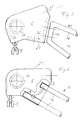
- a coin deposit lock 2, shown schematically in FIG. 1, is held on this shorter handle support arm 1 in a manner described in detail below.
- a receptacle 22 is provided on an outer surface 21a of a housing 21 of the coin deposit lock 2 facing the handle 5, which, like the housing 21, is preferably made of an elastic but resistant plastic and with the housing 21 forms a unit.
- the handle 5 is accommodated in the receptacle 22 by pushing it in and, if necessary, can be secured to the receptacle 22 by a screw inserted from the underside of the handle. In the usual way, the handle 5 is firmly connected to the other, unshortened handle support arm provided on the left side by screwing.
- a reception opening 23 is indicated by dashed lines above the shorter handle support arm 1, into which a key can be inserted, which key is connected by a chain to a transport trolley which has been properly parked and coupled to another transport trolley or a collection point.
- a corresponding chain 3 is attached to the diametrically opposite side of the housing 21 of the coin-operated lock 2 and is indicated in FIG. 2 only by a few chain links.
- a coin inserting and dispensing slot 24 is indicated by dashed lines in the housing 21 of the coin deposit lock 2.
- the end 5a of the handle 5 accommodated in the receptacle 22 is indicated in FIG. 1 by two thin circles.
- the dimension between the center axis of the handle 5 indicated by dash-dotted lines and the shorter handle support arm 1 is such that the handle 5 remains in its previous position and is securely held.
- the coin deposit lock 2 is essentially accommodated in the area or space which has previously been filled by the U-shaped end of a handle support arm provided in the known shopping trolley embodiments and a handle pocket provided on the free end of such a handle support arm , on which an approach corresponding to the approach 22 for receiving the handle 5 is formed.
- the coin deposit lock 2 attached to the shorter handle support arm 1 is attached as an extension of the shorter handle support arm 1 and is thus integrated after or on the transport trolley according to the invention.
- the space required by the integrated coin deposit lock 2 is practically hardly or at most only insignificantly larger than the space previously occupied by the handle pocket provided for screwing the handle 5 there.
- FIG. 3 to 7 show various advantageous configurations of a shorter handle support arm 1 and correspondingly adapted designs of the housing 21 of the coin deposit lock 2.
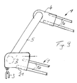
- the shorter handle support arm 1 shown in FIG. 3 its two legs 1a, which run obliquely downwards, are rigidly connected to one another by a connecting part 1b, so that the fixed predetermined positional relationship of the two legs 1a of the handle support arm 1 is secured.
- an L-shaped holding part shown in dashed lines in FIG.
- FIG. 1 A further advantageous embodiment of the front end of the shorter handle support arm 1 is shown schematically in FIG.
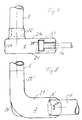
- the free end of the shorter handle support arm 1 its two legs 1a are of different lengths, namely in FIG. 4 the lower leg is longer than the upper leg.
- correspondingly deep recesses 7 are provided in the housing 21, into which the corresponding legs 1a of the shorter handle support arm 1 can be inserted and then secured in this position by means of screws, for which purpose corresponding opening openings 27 in the housing 21 are provided.
- the upper leg 1a ′ which is shorter in FIG. 5 is bent approximately at a right angle in the direction of the longer leg 1a in FIG.
- the bent part of the other leg 1a' is accommodated in a corresponding recess 8 in the housing 21.
- the housing 21 is then secured to the bent part of the leg 1a 'of the shorter handle support arm 1 by means of at least one screw.
- the shorter handle support arm 1 its two legs 1a are approximately of the same length.
- a support plate 9 is fastened, preferably welded, to the two legs 1a of approximately the same length. If, for example, a holding part corresponding to the L-shaped holding part 26 in FIG. 3 is accommodated and integrated in the housing 21 of the coin-operated lock 2, the coin-operated lock 2 is in turn preferably fastened to the support plate 9 of the shorter handle support arm 1 by means of screws.
- FIG. 7 shows an advantageous development of the configuration according to FIG. 6.
- a support plate 9 'fastened to the legs 1a of approximately the same length of the shorter handle support arm 1 is accommodated in a recess 29 in the housing 2, the recess 29 being designed such that it supports the inserted support plate 9' and the front end of the two Legs 1a grips positively.
- the housing 21 is secured to the support plate 9 by means of screws.
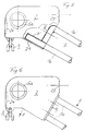
- FIG. 8 A top view of a modified embodiment of a housing 21 'of the coin deposit lock 2 is shown in FIG. 8, on which a receptacle 22' corresponding to the receptacle 22 in FIG. 1 is formed as an integrated part, on which the handle 5 is held and is secured accordingly if necessary.
- the housing 21 ′ facing a shorter handle support tube 10 At the end of the housing 21 ′ facing a shorter handle support tube 10, the latter has a recess adapted to this handle support tube 10 8 'on.
- the housing 21 'of the coin deposit lock 2 is secured to the shorter handle support tube 10 again, for example, by means of a screw introduced through a bore 25'.
- FIG. 9 shows an embodiment of a shopping trolley, not shown, which has two short handle support arms 1.
- a coin deposit lock 2 is fastened to the handle support arm 1 located further forward in FIG. 9, for example in the manner described in detail in connection with the embodiment shown in FIG.
- an adapter part 4 which corresponds essentially to the housing 21 of the coin deposit lock 2 in terms of dimensions, is fastened at its front end, with which in a known manner Way, the tubular handle 5 is screwed tight.
Landscapes
- Physics & Mathematics (AREA)
- General Physics & Mathematics (AREA)
- Handcart (AREA)
- Multiple-Way Valves (AREA)
- Devices That Are Associated With Refrigeration Equipment (AREA)
- Catching Or Destruction (AREA)
- Crystals, And After-Treatments Of Crystals (AREA)
- Glass Compositions (AREA)
- Purses, Travelling Bags, Baskets, Or Suitcases (AREA)
Abstract
Description
Die Erfindung betrifft einen Transportwagen, der in einen gleichartig ausgeführten Transportwagen einschiebbar ist und mit einer zur Aufnahme von Waren oder Transportgut versehenen Einrichtung ausgestattet ist, an deren rückwärtigen Ende auf beiden Seiten durch einen im allgemeinen rohrförmigen Griff verbundene, am freien Ende etwa U-förmig ausgeführte Grifftragarme oder Grifftragrohre fest angebracht sind, in deren Bereich ein Münzpfandschloß angeordnet ist, das ein gegenseitiges An- und Abkoppeln von Transportwagen mit und ohne Inanspruchnahme einer Sammelstelle ermöglicht.The invention relates to a transport trolley which can be inserted into a transport trolley of the same type and is equipped with a device provided for receiving goods or transport goods, at the rear end of which is connected on both sides by a generally tubular handle and is approximately U-shaped at the free end Executed handle support arms or handle support tubes are firmly attached, in the area of which a coin deposit lock is arranged, which enables a mutual coupling and uncoupling of trolleys with and without using a collection point.
Solche Transport- oder Einkaufswagen mit Münzpfandschlössern sind beispielsweise aus den deutschen Patenten 2 554 916 und 2 900 367 sowie aus den europäischen Patenten 70 997 und 199 274 bekannt. Solche Transport- oder Einkaufswagen werden auf Pfandbasis ausgeliehen und lassen sich entweder untereinander an- und abkoppeln und/oder an fest installierten Sammelstellen gezielt ankoppeln und damit einsammeln, um zu jeder Zeit wieder ausgeliehen werden zu können.Such transport or shopping trolleys with coin-operated locks are known, for example, from
Durch derartige Einkaufswagen-Sammel- und -Ausleihsysteme kann insbesondere in Supermärkten vermieden werden, daß beispielsweise leere Einkaufswagen wahllos und ungenutzt auf Parkplätzen, auf den Zufahrtsstraßen u.ä. herumstehen. An diesen Einkaufswagen müssen jedoch die Münzpfandschlösser an geeigneten Stellen so angebracht sein, daß sowohl ein Ineinanderschieben als auch eine bequeme Handhabung der Einkaufswagen wagen erhalten bleiben.Such shopping cart collection and loan systems can be used to prevent, in particular in supermarkets, that, for example, empty shopping carts can be used indiscriminately and unused in parking lots, on the access roads and the like. stand around. However, the coin deposit locks must be attached to these shopping trolleys at suitable points in such a way that both pushing one into the other and convenient handling of the shopping trolleys dare to remain.
Bei einem Anbringen eines beispielsweise aus dem DE-PS 2 554 916 bekannten Münzpfandschlosses an Einkaufswagen ergeben sich vor allem dadurch Schwierigkeiten, daß dieses Münzpfandschloß aufgrund seiner Größe teilweise in den Ladebereich des Korbes eines Einkaufswagens hineinragt, und dadurch ein Beladen des Korbes von der Griffseite des Einkaufswagens her zumindest beeinträchtigt, wenn nicht sogar behindert wird.When attaching a coin deposit lock, for example from DE-PS 2 554 916, to shopping trolleys, difficulties arise primarily because this coin deposit lock partially projects into the loading area of the basket of a shopping trolley due to its size, and thereby loading the basket from the handle side of the The cart is at least affected, if not obstructed.
Da die aus dem DE-PS 2 900 367 und dem europäischen Patent 70 997 bekannten Münzpfandschlösser erheblich kleiner ausgeführt sind als das vorstehend beschriebene Münzpfandschloß, lassen sich diese Münzpfandschlösser ohne Schwierigkeit im rückwärtigen Bereich des Einkaufswagens an dem dort vorgesehenen Griff befestigen. Bei diesen Münzpfandschlössern besteht jedoch die Gefahr, daß sie entweder absichtlich bezüglich der Griffachse verdreht werden, oder daß sie im Laufe der Zeit beispielsweise durch Lockerwerden ihre Befestigungselemente ihre Lage etwas verändern.Since the coin deposit locks known from DE-PS 2 900 367 and the European patent 70 997 are made considerably smaller than the coin deposit lock described above, these coin deposit locks can be attached to the handle provided there without difficulty in the rear area of the shopping cart. With these coin-operated locks, however, there is a risk that they will either be intentionally rotated with respect to the handle axis, or that they will change their position somewhat over time, for example by loosening their fastening elements.
Der vorstehend angeführte Nachteil ist bei dem aus dem europäischen Patent 199 274 bekannten Münzpfandschloß im wesentlichen dadurch vermieden, daß ein allerdings verhältnismäßig großvolumiges Münzpfandschloß im Bereich eines der beiden Grifftragarme eines Einkaufswagens angeordnet ist und sich dabei einerseits am Grifftragarm und andererseits aber auch noch an dem zwischen den beiden Grifftragarmen vorgesehenen Griff abstützt. Nachteilig bei diesem aus dem EP 199 274 bekannten Münzpfandschloß ist jedoch, das es einerseits immer an dem freien Ende eines U-förmig ausgeführten Grifftragarms abgestützt sein muß und andererseits auch noch in beachtlichem Maße in den Griffbereich hinein vorsteht und dadurch den an dem Griff zur Verfügung stehenden Platz in nicht unerheblichem Maße einschränkt.The above-mentioned disadvantage is essentially avoided in the coin deposit lock known from European Patent 199 274 by the fact that a relatively large-volume coin deposit lock is arranged in the area of one of the two handle support arms of a shopping cart and is located on the one hand on the handle support arm and on the other hand also on the between supports the two handle support arms provided. A disadvantage of this coin deposit lock known from EP 199 274, however, is that on the one hand it always has to be supported on the free end of a U-shaped handle support arm and on the other hand it also protrudes to a considerable extent into the handle area and is therefore available on the handle standing space to a not inconsiderable degree.
Aus der DE-A-37 14 115 ist es bekannt, einen Teil des Volumens der Schiebegriffeinrichtung zur Gestaltung und Unterbringung des Münzpfandschlosses zu verwenden, dergestalt, daß das Münzpfandschloß zumindest mit einem Schiebegriffabschnitt auf einer Seite verbunden ist, und auf der anderen Seite an der Griffkappe befestigt ist, welche Grifftragarme bzw. Grifftragrohr mit dem Schiebegriff verbindet.From DE-A-37 14 115 it is known to use part of the volume of the push handle device for designing and accommodating the coin deposit lock in such a way that the coin deposit lock is connected to at least one push handle section on one side and on the other side on the Handle cap is attached, which connects handle support arms or handle support tube with the push handle.
Aufgabe der Erfindung ist es daher, einen Transportwagen der eingangs beschriebenen Art so auszubilden, daß unter Vermeidung der verschiedenen Nachteile der bekannten Transportwagen-Ausführungen ein Münzpfandschloß zumindest weitgehend allein im Bereich eines der Grifftragarme oder eines der Grifftragrohre integrierbar ist.The object of the invention is therefore to provide a trolley type described at the outset so that, while avoiding the various disadvantages of the known trolley designs, a coin deposit lock can be integrated at least largely solely in the area of one of the handle support arms or one of the handle support tubes.
Gemäß der Erfindung ist dies bei einem Transportwagen nach dem Oberbegriff des Anspruchs 1 dadurch erreicht, daß einer der Grifftragarme oder eines der Grifftragrohre kürzer ausgebildet ist, und daß an dem kürzeren Grifftragarm oder -rohr ein Münzpfandschloß so befestigt ist, daß das Gehäuse des Münzpfandschlosses mit der senkrecht verlaufenden Mittenebene der Grifftragarme oder -rohre zusammenfällt. Gemäß einer bevorzugten Ausführungsform der Erfindung ist ferner an einer Außenfläche des Gehäuses des Münzpfandschlosses eine Aufnahme zur Halterung und Sicherung des im allgemeinen rohrförmigen Griffs vorgesehen.According to the invention, this is achieved in a trolley according to the preamble of
Der besondere Vorteil des erfindungsgemäßen Transportwagens ist somit darin zu sehen, daß der Raum, welcher bisher von dem im allgemeinen U-förmig ausgeführten Ende eines der Grifftragarme beansprucht worden ist, nunmehr in platzsparender Weise zur Unterbringung des Münzpfandschlosses ausgenutzt ist. Oder mit anderen Worten, bei dem erfindungsgemäßen Transportwagen ist das Münzpfandschloß so integriert, daß die Außenabmessungen des Transportwagens gerade im Bereich eines der beiden Grifftragarme oder -rohre praktisch denjenigen der bisher verwendeten Transportwagen entsprechen, und daß insbesondere der Platz an dem zwischen den beiden Grifftragarmen oder -rohren vorgesehene Griff praktisch in vollem Umfang zur Verfügung steht.The particular advantage of the trolley according to the invention can thus be seen in the fact that the space which has previously been claimed by the generally U-shaped end of one of the handle support arms is now used in a space-saving manner for accommodating the coin deposit lock. Or in other words, in the transport trolley according to the invention, the coin deposit lock is integrated in such a way that the outer dimensions of the transport trolley, in the area of one of the two handle support arms or tubes, practically correspond to those of the transport trolleys previously used, and in particular that the space between the two handle support arms or -Pipes provided handle is practically fully available.
Nachfolgend wird die Erfindung anhand von bevorzugten Ausführungsformen unter Bezugnahme auf die anliegenden Zeichnungen im einzelnen erläutert. Es zeigen:
- Fig.1
- eine schematische Seitenansicht eines an einem kürzeren Grifftragarm angebrachten Münzpfandschlosses eines erfindungsgemäßen Transportwagens in Form eines Einkaufswagens;
- Fig.2
- eine Draufsicht von oben auf das an dem kürzeren Grifftragarm angebrachte Münzpfandschloß nach Fig.1;
- Fig.3
- in Seitenansicht eine vorteilhafte Ausgestaltung des kürzeren Grifftragarms und ein diesem kürzeren Grifftragarm zugeordnetes Münzpfandschloß;
- Fig.4
- in Seitenansicht eine weitere vorteilhafte Ausgestaltung eines an einem teilweise aufgeschnitten dargestellten Münzpfandschloß vorgesehenen, kürzeren Grifftragarms;
- Fig.5
- wiederum in Seitenansicht eine dritte Ausführungsform eines ebenfalls in einem teilweise aufgeschnitten wiedergegebenen Münzpfandschloß vorgesehenen, kürzeren Grifftragarms;
- Fig.6
- ebenfalls in Seitenansicht eine vierte, vorteilhafte Ausführungsform eines kürzeren Grifftragarms mit daran befestigtem Münzpfandschloß;
- Fig.7
- auch wieder in Seitenansicht eine vorteilhafte Weiterbildung der Ausführungsform nach Fig.6;
- Fig.8
- eine Draufsicht von oben auf eine vorteilhafte Ausgestaltung eines an einem kurzen Grifftragrohr angebrachten Münzpfandschlosses eines Transportwagens, und
- Fig.6
- eine vorteilhafte Halterungsmöglichkeit eines Griffes an einem zwei kürzere Grifftragrarme aufweisenden Einkaufswagen.
- Fig. 1
- a schematic side view of an a shorter handle support arm attached coin deposit lock of a trolley according to the invention in the form of a shopping trolley;
- Fig. 2
- a plan view from above of the coin deposit lock attached to the shorter handle support arm according to Figure 1;
- Fig. 3
- a side view of an advantageous embodiment of the shorter handle support arm and a coin deposit lock associated with this shorter handle support arm;
- Fig. 4
- in side view a further advantageous embodiment of a shorter handle support arm provided on a coin deposit lock shown partially cut away;
- Fig. 5
- again a side view of a third embodiment of a shorter handle support arm also provided in a partially cut-away coin deposit lock;
- Fig. 6
- also a side view of a fourth, advantageous embodiment of a shorter handle support arm with a coin deposit lock attached to it;
- Fig. 7
- an advantageous development of the embodiment according to FIG. 6;
- Fig. 8
- a plan view from above of an advantageous embodiment of a coin deposit lock of a trolley attached to a short handle support tube, and
- Fig. 6
- an advantageous possibility of mounting a handle on a shopping trolley having two shorter handle arms.
Die Erfindung schließt alle gängigen Ausführungsformen von Transportwagen sowie von Einkaufswagen ein, die zur Zeit angeboten und benutzt werden. Dazu zählen beispielsweise alle Einkaufswagen, welche aufgrund ihrer in Fahrtrichtung sich verjüngenden Gestalt zum Zwecke des platzsparenden Stapelns ineinanderschiebbar ausgebildet sind. Üblicherweise haben solche Einkaufswagen ein mit vier Fahrrollen versehenes Fahrgestell, welches einen Korb trägt, der rückseitig durch eine um eine im oberen Bereich befindliche, waagrechte Achse drehbare, in das Korbinnere schwenkbare Klappe begrenzt ist.The invention includes all current embodiments of trolleys and shopping carts that are currently offered and used. These include, for example, all shopping carts which, owing to their shape tapering in the direction of travel, are designed to be able to be pushed into one another for the purpose of space-saving stacking. Such shopping carts usually have a chassis provided with four castors, which carries a basket which is bounded on the rear by a flap which can be rotated about a horizontal axis located in the upper region and can be pivoted into the basket interior.
Am oberen rückwärtigen Ende des Korbes befinden sich bei den bisher üblichen Einkaufswagen auf beiden Seiten jeweils Grifftragarme, die durch einen Griff verbunden sind, der vorzugsweise einen rohrförmigen Querschnitt aufweist und bei den bekannten Einkaufswagen-Ausführungen mit den Grifftragarmen durch Verschrauben fest verbunden ist.At the upper rear end of the basket there are handle support arms on both sides in the previously usual shopping carts, which are connected by a handle, which preferably has a tubular cross section and is firmly connected to the handle support arms by screwing in the known shopping cart designs.
Vorzugsweise auf der in der üblichen Fahrt- bzw. Schieberichtung gesehen rechten Seite eines Einkaufswagens ist, wie in Fig.1 schematisch dargestellt ist, ein kürzerer, im allgemeinen aus zwei schräg nach oben verlaufenden Stäben gebildeter Grifftragarm 1 vorgesehen. An diesem kürzeren Grifftragarm 1 ist ein in Fig.1 schematisch wiedergegebenes Münzpfandschloß 2 in einer nachstehend im einzelnen beschriebenen Weise gehaltert.Preferably, on the right-hand side of a shopping trolley, as seen in the usual direction of travel or sliding, as shown schematically in FIG. 1, a shorter
Wie aus der Draufsicht in Fig.2 zu ersehen ist, ist an einer dem Griff 5 zugewandten Außenfläche 21a eines Gehäuses 21 des Münzpfandschlosses 2 eine Aufnahme 22 vorgesehen, welche ebenso wie das Gehäuse 21 vorzugsweise aus einem elastischen, jedoch widerstandsfähigen Kunststoff hergestellt ist und mit dem Gehäuse 21 eine Einheit bildet. Wie aus Fig.2 zu ersehen sehen ist, ist der Griff 5 durch Hineinschieben in der Aufnahme 22 untergebracht und kann erforderlichenfalls durch eine von der Griffunterseite eingebrachte Schraube an der Aufnahme 22 gesichert sein. In üblicher Weise ist der Griff 5 mit dem anderen, auf der linken Seite vorgesehenen, unverkürzten Grifftragarm durch Verschrauben fest verbunden.As can be seen from the top view in FIG. 2, a
In Fig.1 und 2 ist über dem kürzeren Grifftragarm 1 gestrichelt eine Aufnahmeöffnung 23 angedeutet, in welche ein Schlüssel einführbar ist, welcher mittels einer Kette mit einem ordnungsgemäß abgestellten und an einem anderen Transportwagen bzw. einer Sammelstelle angekoppelten Transportwagen verbunden ist. Eine entsprechende Kette 3 ist an dem der Schlüsselaufnahme 23 diametral gegenüberliegenden Seite des Gehäuses 21 des Münzofandschlosses 2 angebracht und in Fig.2 lediglich durch einige Kettenglieder angedeutet. Ferner ist in dem Gehäuse 21 des Münzpfandschlosses 2 strichliert ein Münzeeinwurf- und -ausgabeschlitz 24 angedeutet. Ferner ist in Fig.1 durch zwei dünne Kreise das in der Aufnahme 22 untergebrachte Ende 5a des Griffes 5 angedeutet.In FIGS. 1 and 2, a
Wie aus den Fig.1 und 2 zu ersehen ist, ist die Abmessung zwischen der strichpunktiert angedeuteten Mittenachse des Griffes 5 und dem kürzeren Grifftragarm 1 so bemessen, daß der Griff 5 in seiner bisherigen Position angeordnet bleibt und sicher gehaltert ist. Dies bedeutet jedoch, daß das Münzpfandschloß 2 im wesentlichen in dem Bereich oder Raum untergebracht ist, welcher bisher von dem U-förmig ausgeführten Ende eines bei den bekannten Einkaufswagen-Ausführungsformen vorgesehenen Grifftragarms sowie einer an dem freien Ende eines solchen Grifftragarms vorgesehenen Grifftasche ausgefüllt worden ist, an welcher ein dem Ansatz 22 entsprechender Ansatz zur Aufnahme des Griffes 5 ausgebildet ist. Mit anderen Worten, das an dem kürzeren Grifftragarm 1 angebrachte Münzpfandschloß 2 ist in Verlängerung des kürzeren Grifftragarms 1 angebracht und somit nach seiner Montage an bzw. in dem erfindungsgemäßen Transportwagen integriert. Hierbei ist der von dem integrierten Münzpfandschloß 2 benötigte Raum praktisch kaum oder allenfalls nur unwesentlich größer als der Raum, welcher bisher von der zur Verschraubung des Griffs 5 dort vorgesehenen Grifftasche eingenommen wurde.As can be seen from FIGS. 1 and 2, the dimension between the center axis of the
In den Fig.3 bis 7 sind verschiedene vorteilhafte Ausgestaltungen eines kürzeren Grifftragarms 1 sowie entsprechend angepaßte Ausführungen des Gehäuses 21 des Münzpfandschlosses 2 dargestellt. So sind in der in Fig.3 wiedergegebenen, vorteilhaften Ausgestaltung des kürzeren Grifftragarms 1 dessen beide schräg nach unten verlaufenden Schenkel 1a durch ein Verbindungsteil 1b starr miteinander verbunden, so daß dadurch die fest vorgegebene Lagebeziehung der beiden Schenkel 1a des Grifftragarms 1 gesichert ist. Im Inneren des Gehäuses 21 des Münzpfandschlosses 2 ist beispielsweise ein in Fig.3 gestrichelt wiedergegebenes, L-förmiges Halteteil fest integriert, so daß das Münzpfandschloß 2 beispielsweise mittels Schrauben fest und sicher an dem Verbindungsteil 1b des Grifftragarms 1 anbringbar ist.3 to 7 show various advantageous configurations of a shorter
In Fig.4 ist eine weitere vorteilhafte Ausgestaltung des vorderen Endes des kürzeren Grifftragarms 1 schematisch wiedergegeben. Bei dieser vorteilhaften Ausgestaltung des freien Endes des kürzeren Grifftragarms 1 sind dessen beiden Schenkel 1a unterschiedlich lang ausgebildet, und zwar ist in Fig.4 der untere Schenkel länger als der obere Schenkel. Zur Aufnahme dieser beiden unterschiedlich langen Schenkel 1a sind in dem Gehäuse 21 entsprechend tief ausgebildete Vertiefungen 7 vorgesehen, in welche die entsprechenden Schenkel 1a des kürzeren Grifftragarms 1 einschiebbar sind und dann in dieser Lage mittels Schrauben gesichert sind, wofür in dem Gehäuse 21 entsprechende Aufnahmeöffnungen 27 vorgesehen sind.A further advantageous embodiment of the front end of the shorter
Bei der in Fig.5 dargestellten Ausgestaltung des kürzeren Grifftragarms 1 ist der in Fig.5 kürzere, obere Schenkel 1a' etwa rechtwinklig in Richtung zu dem längeren, in Fig.5 unteren Schenkel 1a umgebogen. Nach einem Einschieben des längeren Schenkels 1a in eine entsprechend bemessene Vertiefung 7' im Gehäuse 21 wird der umgebogene Teil des anderen Schenkels 1a' in einer entsprechenden Ausnehmung 8 im Gehäuse 21 untergebracht. Mittels mindestens einer Schraube wird dann das Gehäuse 21 an dem umgebogenen Teil des Schenkels 1a' des kürzeren Grifftragarms 1 gesichert.In the embodiment of the shorter
Bei einer weiteren vorteilhaften Ausgestaltung des kürzeren Grifftragarms 1 sind dessen beide Schenkel 1a etwa gleich lang. An den beiden etwa gleich langen Schenkeln 1a ist eine Tragplatte 9 befestigt, vorzugsweise angeschweißt. Wenn in dem Gehäuse 21 des Münzpfandschlosses 2 beispielsweise ein dem L-förmigen Halteteil 26 in Fig.3 entsprechendes Halteteil untergebracht und integriert ist, ist das Münzpfandschloß 2 vorzugsweise wiederum mittels Schrauben an der Trageplatte 9 des kürzeren Grifftragarms 1 befestigt.In a further advantageous embodiment of the shorter
In Fig.7 ist eine vorteilhafte Weiterbildung der Ausgestaltung nach Fig.6 dargestellt. Bei dieser Ausführungsform ist eine an den etwa gleich langen Schenkeln 1a des kürzeren Grifftragarms 1 befestigte Tragplatte 9' in einer Ausnehmung 29 des Gehäuses 2 untergebracht, wobei die Ausnehmung 29 so ausgebildet ist, daß sie die eingebrachte Tragplatte 9' sowie das vordere Ende der beiden Schenkel 1a formschlüssig umgreift. Erforderlichenfalls ist das Gehäuse 21 mittels Schrauben an der Tragplatte 9 gesichert.FIG. 7 shows an advantageous development of the configuration according to FIG. 6. In this embodiment, a support plate 9 'fastened to the
In Fig.8 ist in einer Draufsicht von oben eine modifizierte Ausgestaltung eines Gehäuses 21' des Münzpfandschlosses 2 wiedergegeben, an welchem eine der Aufnahme 22 in Fig.1 entsprechende Aufnahme 22' als ein integrierter Teil ausgebildet ist, an welchem der Griff 5 gehaltert und erforderlichenfalls entsprechend gesichert ist. An dem einem kürzeren Grifftragrohr 10 zugewandten Ende des Gehäuses 21' weist letzteres eine diesem Grifftragrohr 10 angepaßte Ausnehmung 8' auf. Das Gehäuse 21' des Münzpfandschlosses 2 ist an dem kürzeren Grifftragrohr 10 beispielsweise wiederum mittels einer durch eine Bohrung 25' eingebrachten Schraube gesichert.A top view of a modified embodiment of a housing 21 'of the
In Fig.9 ist schließlich noch eine Ausführungsform eines nicht näher dargestellten Einkaufswagens angedeutet, welcher zwei kurze Grifftragarme 1 aufweist. Hierbei ist an dem einen in Fig.9 weiter vorne liegenden Grifftragarm 1 ein Münzpfandschloß 2 beispielsweise in der Weise befestigt, wie in Verbindung mit der in Fig.4 dargestellten Ausführungsform im einzelnen beschrieben ist. Zur Halterung und Sicherung des Griffes 5 an dem anderen, in Fig.9 weiter hinten liegenden kurzen Grifftragarm 1 ist an dessen vorderen Ende ein dem Gehäuse 21 des Münzpfandschlosses 2 in den Abmessungen im wesentlichen entsprechendes, spiegelbildlich ausgebildetes Adapterteil 4 befestigt, mit welchem in bekannter Weise der rohrförmige Griff 5 fest verschraubt ist.Finally, FIG. 9 shows an embodiment of a shopping trolley, not shown, which has two short
Claims (8)
- Transport trolley which is adapted to be inserted into a similarly constructed transport trolley and is equipped with a means which is provided for accommodating goods or transport material and at the rear end of which on both sides grip support arms (1) or grip support tubes (10) are fixedly attached which are connected by a generally tubular grip (5) and made substantially U-shaped at the free end and in the region of which a coin deposit lock (2) is arranged which permits a mutual coupling and decoupling of transport trolleys with or without requiring a collection point, characterized in that on of the grip support arms (1) or one of the grip support tubes (10) is made shorter, that on the shorter grip support arm (1) or tube (10) the coin deposit lock (2) is mounted in such a manner that the housing (21) of the coin deposit lock (2) coincides with the vertically extending centre plane of the grip support arms (1) or tubes (10).
- Transport trolley according to claim 1, characterized in that on an outer surface (21a) of the housing (21) of the coin deposit lock (2) a socket (22) is provided for holding and securing the tubular grip (5).
- Transport trolley according to claims 1 and 2, characterized in that the housing (21) of the coin deposit lock (2) is adapted to be attached to a member (1b) connecting the two legs (1a) of the shorter grip support arm (1).
- Transport trolley according to claims 1 and 2, characterized in that one or both legs (1a) of the one shorter grip support arm (1) is or are insertable into correspondingly deeply formed depressions (7) of the housing (21) of the coin deposit lock (2), and that the coin deposit lock (2) can be secured in this position with respect to the shorter grip support arm (1).
- Transport trolley according to claim 1, characterized in that the shorter (1a') of the two legs (1a) of different length of the shorter grip support arm (1) is bent substantially perpendicularly in the direction towards the longer of the two legs (1a) so that the housing (21) of the coin deposit lock (2) after the accommodation of the longer leg (1a) in a correspondingly dimensioned housing depression (7) can be secured to the shorter bent leg (1a').
- Transport trolley according to claim 1, characterized in that the ends of the two legs (1a) of the shorter grip support arm (1) have substantially the same length and that to the two substantially equilength legs (1a) of the shorter grip support arm (1) a support plate (9) is secured to which the housing (21) of the coin deposit lock (2) can be attached.
- Transport trolley according to claim 6, characterized in that the support plate (9') attached to the ends of the two substantially equilength legs (1a) of the shorter grip support arm (1) is enclosed by a form-locking recess (29) of the housing (21) of the coin deposit lock (2).
- Transport trolley according to claim 1, characterized in that in the case of a transport trolley having two short grip support arms (1) or tubes (10) on the one grip support arm (1) or tube (10) a coin deposit lock (2) is mounted and on the other grip support arm (1) or tube (10) for the analogous extension thereof an adapter member (4) corresponding in dimensions to the housing (21) of the coin deposit lock (2) and made laterally inverted with respect thereto is mounted.
Priority Applications (5)
| Application Number | Priority Date | Filing Date | Title |
|---|---|---|---|
| DK90103057.7T DK0442016T3 (en) | 1990-02-16 | 1990-02-16 | Transport trolley |
| EP90103057A EP0442016B1 (en) | 1990-02-16 | 1990-02-16 | Transport trolley |
| AT9090103057T ATE105434T1 (en) | 1990-02-16 | 1990-02-16 | TRANSPORT TROLLEY. |
| DE59005625T DE59005625D1 (en) | 1990-02-16 | 1990-02-16 | Dolly. |
| ES90103057T ES2052992T3 (en) | 1990-02-16 | 1990-02-16 | WHEELBARROW. |
Applications Claiming Priority (1)
| Application Number | Priority Date | Filing Date | Title |
|---|---|---|---|
| EP90103057A EP0442016B1 (en) | 1990-02-16 | 1990-02-16 | Transport trolley |
Publications (2)
| Publication Number | Publication Date |
|---|---|
| EP0442016A1 EP0442016A1 (en) | 1991-08-21 |
| EP0442016B1 true EP0442016B1 (en) | 1994-05-04 |
Family
ID=8203658
Family Applications (1)
| Application Number | Title | Priority Date | Filing Date |
|---|---|---|---|
| EP90103057A Expired - Lifetime EP0442016B1 (en) | 1990-02-16 | 1990-02-16 | Transport trolley |
Country Status (5)
| Country | Link |
|---|---|
| EP (1) | EP0442016B1 (en) |
| AT (1) | ATE105434T1 (en) |
| DE (1) | DE59005625D1 (en) |
| DK (1) | DK0442016T3 (en) |
| ES (1) | ES2052992T3 (en) |
Families Citing this family (4)
| Publication number | Priority date | Publication date | Assignee | Title |
|---|---|---|---|---|
| DE4111178A1 (en) * | 1991-04-06 | 1992-10-08 | Systec Ausbausysteme Gmbh | TRANSPORT CARRIAGE WITH COIN LOCK |
| ATE145743T1 (en) * | 1992-09-11 | 1996-12-15 | Wanzl Entwicklung Gmbh | TRANSPORT TROLLEY WITH A COIN LOCK |
| DE19605805B4 (en) * | 1996-02-16 | 2007-07-12 | Systec Pos-Technology Gmbh | Dolly with deposit lock |
| DE19830297A1 (en) * | 1998-07-07 | 2000-01-13 | Wanzl Metallwarenfabrik Kg | Sliding device for attachment to a shopping cart |
Family Cites Families (6)
| Publication number | Priority date | Publication date | Assignee | Title |
|---|---|---|---|---|
| US3288478A (en) * | 1964-01-13 | 1966-11-29 | Wesley H Powers | Coin operated adding machine for grocery chain store carts |
| DE3405101A1 (en) * | 1984-02-14 | 1985-08-22 | Theresia 7799 Illmensee Bohler | COUPLING DEVICE FOR SHOPPING CART AND THE LIKE |
| DE3515069A1 (en) * | 1985-04-26 | 1986-11-06 | Rudolf Wanzl Kg, 8874 Leipheim | SHOPPING VENTURE |
| US4683609A (en) * | 1986-04-08 | 1987-08-04 | Cari-All Inc. | Shopping cart handle having an integral lock pin |
| DE8614831U1 (en) * | 1986-06-02 | 1986-07-17 | Sonnendorfer, Horst, 8034 Germering | Shopping venture |
| DE3714115A1 (en) * | 1987-04-28 | 1988-11-10 | Wanzl Rudolf Gmbh Co Kg | Coin-operated lock |
-
1990
- 1990-02-16 ES ES90103057T patent/ES2052992T3/en not_active Expired - Lifetime
- 1990-02-16 DK DK90103057.7T patent/DK0442016T3/en active
- 1990-02-16 EP EP90103057A patent/EP0442016B1/en not_active Expired - Lifetime
- 1990-02-16 DE DE59005625T patent/DE59005625D1/en not_active Expired - Fee Related
- 1990-02-16 AT AT9090103057T patent/ATE105434T1/en not_active IP Right Cessation
Also Published As
| Publication number | Publication date |
|---|---|
| ATE105434T1 (en) | 1994-05-15 |
| DE59005625D1 (en) | 1994-06-09 |
| DK0442016T3 (en) | 1994-07-18 |
| ES2052992T3 (en) | 1994-07-16 |
| EP0442016A1 (en) | 1991-08-21 |
Similar Documents
| Publication | Publication Date | Title |
|---|---|---|
| EP0199274B1 (en) | Transport trolley | |
| DE3010382A1 (en) | BICYCLE RACK | |
| EP0790586B1 (en) | Transport trolley with a refunding lock | |
| EP0442016B1 (en) | Transport trolley | |
| EP1358637B1 (en) | Deposit-operated lock for a trolley | |
| EP0231934B1 (en) | Method and apparatus for dispensing and collecting trolleys, especially shopping and luggage trolleys | |
| DE4118514A1 (en) | TRANSPORT CARRIAGE WITH COIN LOCK | |
| WO2000002169A1 (en) | Sliding device for attachment to a shopping trolley | |
| EP0844592B1 (en) | Transport trolley | |
| EP0562264B1 (en) | Hand-driven transport carriage | |
| EP0421101A1 (en) | Device for linking shopping trolleys | |
| DE4111178A1 (en) | TRANSPORT CARRIAGE WITH COIN LOCK | |
| DE102019135039A1 (en) | Trolleys for use as a bicycle trailer or hand cart | |
| EP1485888A2 (en) | Deposit lock for a transport car | |
| EP0569915B1 (en) | Load carrier | |
| DE8614831U1 (en) | Shopping venture | |
| DE20011002U1 (en) | Cart, especially sack, piercing or stacking cart | |
| EP0629543B1 (en) | Support post coupling device for roofframes of trucks and trailers | |
| DE9308623U1 (en) | Receiving body for the deposit lock of a shopping cart | |
| DE8223340U1 (en) | DEVICE FOR FASTENING A WHEEL IN THE CHASSIS OF A TRANSPORT VEHICLE FOR GOODS, ESPECIALLY IN SELF-SERVICE SHOPS | |
| DE9308624U1 (en) | Shopping cart with deposit lock | |
| DE19814062A1 (en) | Stackable dolly | |
| DE19544574A1 (en) | Swing link suspension for wheel on wheelbarrow | |
| EP3838711A1 (en) | Trolley for use as a bicycle trailer or as a hand trolley | |
| DE9001468U1 (en) | Handcart for transporting barrels |
Legal Events
| Date | Code | Title | Description |
|---|---|---|---|
| PUAI | Public reference made under article 153(3) epc to a published international application that has entered the european phase |
Free format text: ORIGINAL CODE: 0009012 |
|
| 17P | Request for examination filed |
Effective date: 19901221 |
|
| AK | Designated contracting states |
Kind code of ref document: A1 Designated state(s): AT BE CH DE DK ES FR GB GR IT LI LU NL SE |
|
| 17Q | First examination report despatched |
Effective date: 19930809 |
|
| GRAA | (expected) grant |
Free format text: ORIGINAL CODE: 0009210 |
|
| AK | Designated contracting states |
Kind code of ref document: B1 Designated state(s): AT BE CH DE DK ES FR GB GR IT LI LU NL SE |
|
| REF | Corresponds to: |
Ref document number: 105434 Country of ref document: AT Date of ref document: 19940515 Kind code of ref document: T |
|
| REF | Corresponds to: |
Ref document number: 59005625 Country of ref document: DE Date of ref document: 19940609 |
|
| ITF | It: translation for a ep patent filed | ||
| REG | Reference to a national code |
Ref country code: ES Ref legal event code: FG2A Ref document number: 2052992 Country of ref document: ES Kind code of ref document: T3 |
|
| REG | Reference to a national code |
Ref country code: DK Ref legal event code: T3 |
|
| GBT | Gb: translation of ep patent filed (gb section 77(6)(a)/1977) |
Effective date: 19940720 |
|
| REG | Reference to a national code |
Ref country code: GR Ref legal event code: FG4A Free format text: 3012211 |
|
| ET | Fr: translation filed | ||
| EAL | Se: european patent in force in sweden |
Ref document number: 90103057.7 |
|
| PGFP | Annual fee paid to national office [announced via postgrant information from national office to epo] |
Ref country code: GR Payment date: 19950131 Year of fee payment: 6 |
|
| PGFP | Annual fee paid to national office [announced via postgrant information from national office to epo] |
Ref country code: LU Payment date: 19950201 Year of fee payment: 6 |
|
| PGFP | Annual fee paid to national office [announced via postgrant information from national office to epo] |
Ref country code: BE Payment date: 19950210 Year of fee payment: 6 |
|
| PGFP | Annual fee paid to national office [announced via postgrant information from national office to epo] |
Ref country code: SE Payment date: 19950216 Year of fee payment: 6 |
|
| PGFP | Annual fee paid to national office [announced via postgrant information from national office to epo] |
Ref country code: CH Payment date: 19950221 Year of fee payment: 6 |
|
| PGFP | Annual fee paid to national office [announced via postgrant information from national office to epo] |
Ref country code: AT Payment date: 19950223 Year of fee payment: 6 |
|
| PGFP | Annual fee paid to national office [announced via postgrant information from national office to epo] |
Ref country code: DK Payment date: 19950227 Year of fee payment: 6 |
|
| PGFP | Annual fee paid to national office [announced via postgrant information from national office to epo] |
Ref country code: NL Payment date: 19950228 Year of fee payment: 6 |
|
| PLBE | No opposition filed within time limit |
Free format text: ORIGINAL CODE: 0009261 |
|
| STAA | Information on the status of an ep patent application or granted ep patent |
Free format text: STATUS: NO OPPOSITION FILED WITHIN TIME LIMIT |
|
| RAP4 | Party data changed (patent owner data changed or rights of a patent transferred) |
Owner name: SYSTEC AUSBAUSYSTEME GMBH |
|
| REG | Reference to a national code |
Ref country code: CH Ref legal event code: PFA Free format text: SYSTEC AUSBAUSYSTEME GMBH |
|
| 26N | No opposition filed | ||
| PG25 | Lapsed in a contracting state [announced via postgrant information from national office to epo] |
Ref country code: LU Free format text: LAPSE BECAUSE OF NON-PAYMENT OF DUE FEES Effective date: 19960216 Ref country code: DK Effective date: 19960216 Ref country code: AT Effective date: 19960216 |
|
| REG | Reference to a national code |
Ref country code: DK Ref legal event code: EBP |
|
| PG25 | Lapsed in a contracting state [announced via postgrant information from national office to epo] |
Ref country code: SE Effective date: 19960217 |
|
| PG25 | Lapsed in a contracting state [announced via postgrant information from national office to epo] |
Ref country code: LI Free format text: LAPSE BECAUSE OF NON-PAYMENT OF DUE FEES Effective date: 19960228 Ref country code: CH Free format text: LAPSE BECAUSE OF NON-PAYMENT OF DUE FEES Effective date: 19960228 Ref country code: BE Effective date: 19960228 |
|
| BERE | Be: lapsed |
Owner name: SYSTEC AUSBAUSYSTEME G.M.B.H. Effective date: 19960228 |
|
| PG25 | Lapsed in a contracting state [announced via postgrant information from national office to epo] |
Ref country code: GR Free format text: THE PATENT HAS BEEN ANNULLED BY A DECISION OF A NATIONAL AUTHORITY Effective date: 19960831 |
|
| PG25 | Lapsed in a contracting state [announced via postgrant information from national office to epo] |
Ref country code: NL Effective date: 19960901 |
|
| REG | Reference to a national code |
Ref country code: CH Ref legal event code: PL |
|
| REG | Reference to a national code |
Ref country code: GR Ref legal event code: MM2A Free format text: 3012211 |
|
| NLV4 | Nl: lapsed or anulled due to non-payment of the annual fee |
Effective date: 19960901 |
|
| PGFP | Annual fee paid to national office [announced via postgrant information from national office to epo] |
Ref country code: GB Payment date: 20010129 Year of fee payment: 12 |
|
| PGFP | Annual fee paid to national office [announced via postgrant information from national office to epo] |
Ref country code: FR Payment date: 20010215 Year of fee payment: 12 |
|
| PGFP | Annual fee paid to national office [announced via postgrant information from national office to epo] |
Ref country code: ES Payment date: 20010221 Year of fee payment: 12 |
|
| PGFP | Annual fee paid to national office [announced via postgrant information from national office to epo] |
Ref country code: DE Payment date: 20010302 Year of fee payment: 12 |
|
| REG | Reference to a national code |
Ref country code: GB Ref legal event code: IF02 |
|
| PG25 | Lapsed in a contracting state [announced via postgrant information from national office to epo] |
Ref country code: GB Free format text: LAPSE BECAUSE OF NON-PAYMENT OF DUE FEES Effective date: 20020216 |
|
| PG25 | Lapsed in a contracting state [announced via postgrant information from national office to epo] |
Ref country code: ES Free format text: LAPSE BECAUSE OF NON-PAYMENT OF DUE FEES Effective date: 20020218 |
|
| PG25 | Lapsed in a contracting state [announced via postgrant information from national office to epo] |
Ref country code: DE Free format text: LAPSE BECAUSE OF NON-PAYMENT OF DUE FEES Effective date: 20020903 |
|
| GBPC | Gb: european patent ceased through non-payment of renewal fee |
Effective date: 20020216 |
|
| PG25 | Lapsed in a contracting state [announced via postgrant information from national office to epo] |
Ref country code: FR Free format text: LAPSE BECAUSE OF NON-PAYMENT OF DUE FEES Effective date: 20021031 |
|
| REG | Reference to a national code |
Ref country code: FR Ref legal event code: ST |
|
| REG | Reference to a national code |
Ref country code: ES Ref legal event code: FD2A Effective date: 20030922 |
|
| PG25 | Lapsed in a contracting state [announced via postgrant information from national office to epo] |
Ref country code: IT Free format text: LAPSE BECAUSE OF NON-PAYMENT OF DUE FEES;WARNING: LAPSES OF ITALIAN PATENTS WITH EFFECTIVE DATE BEFORE 2007 MAY HAVE OCCURRED AT ANY TIME BEFORE 2007. THE CORRECT EFFECTIVE DATE MAY BE DIFFERENT FROM THE ONE RECORDED. Effective date: 20050216 |