EP0609663A1 - Shopping trolley - Google Patents
Shopping trolley Download PDFInfo
- Publication number
- EP0609663A1 EP0609663A1 EP94100326A EP94100326A EP0609663A1 EP 0609663 A1 EP0609663 A1 EP 0609663A1 EP 94100326 A EP94100326 A EP 94100326A EP 94100326 A EP94100326 A EP 94100326A EP 0609663 A1 EP0609663 A1 EP 0609663A1
- Authority
- EP
- European Patent Office
- Prior art keywords
- shopping cart
- crate
- box
- chassis
- cross strut
- Prior art date
- Legal status (The legal status is an assumption and is not a legal conclusion. Google has not performed a legal analysis and makes no representation as to the accuracy of the status listed.)
- Granted
Links
Images

Classifications
-
- B—PERFORMING OPERATIONS; TRANSPORTING
- B62—LAND VEHICLES FOR TRAVELLING OTHERWISE THAN ON RAILS
- B62B—HAND-PROPELLED VEHICLES, e.g. HAND CARTS OR PERAMBULATORS; SLEDGES
- B62B3/00—Hand carts having more than one axis carrying transport wheels; Steering devices therefor; Equipment therefor
- B62B3/14—Hand carts having more than one axis carrying transport wheels; Steering devices therefor; Equipment therefor characterised by provisions for nesting or stacking, e.g. shopping trolleys
- B62B3/1468—Additional trays
-
- B—PERFORMING OPERATIONS; TRANSPORTING
- B62—LAND VEHICLES FOR TRAVELLING OTHERWISE THAN ON RAILS
- B62B—HAND-PROPELLED VEHICLES, e.g. HAND CARTS OR PERAMBULATORS; SLEDGES
- B62B2202/00—Indexing codes relating to type or characteristics of transported articles
- B62B2202/12—Boxes, Crates
Definitions
- the present invention relates to a shopping cart with a chassis and a goods container placed thereon, in the rear area of the shopping cart a crate shelf is provided which comprises two fixed longitudinally offset holding elements for a crate, one of which serves as a support for the floor and the other serves as an attachment for at least one wall of a box to be accommodated.
- Such a shopping cart is known from German Patent 30 43 599.
- a cross strut and a stop are provided as holding elements for the box.
- the cross strut which serves as a support for the crate to be accommodated in the crate storage, connects the long sides of the chassis to one another in the lower rear area; and the stop, which together with the side supports supporting the basket serves as a partial lateral boundary for the box, is arranged in front of the cross strut and at a different height than this.
- the known crate storage is thus open to the rear, opposite to the direction of travel; a box is placed in the storage area from behind inserted until it touches the stop. The box is located under the goods container and takes a position inclined towards the front in the direction of travel.
- a disadvantage of the known crate rack is that bottles of a beverage crate accommodated in the crate rack are not accessible. Furthermore, the known crate storage can only be realized with shopping carts in which there is sufficient space under the goods container; in the case of shopping carts with a deeply pulled-down goods container, however, the known crate shelf cannot be used. The pushing in of a heavy box from behind under the goods container of the shopping cart in a bent position also places a heavy load on the back of the person in question.
- the present invention has for its object to provide a generic shopping cart in which the disadvantages mentioned above do not occur.
- a shopping cart is to be created in which the bottles of a box accommodated in the box rack are accessible from above, the box rack also being used in shopping carts with a low-lying goods container should be usable and the loading of the crate storage with a heavy crate is possible as gently as possible for the back of the person concerned.
- this object is achieved in that the front holding element as a support for the bottom of the box and that the rear holding element is cranked rearward and designed as an attachment for the two side and the rear wall of the box, so that a box obliquely inclined backwards from above into the crate shelf and a crate accommodated in the crate shelf assumes an obliquely backward inclined position.
- the box to be accommodated in the box rack is therefore not pushed from behind under the goods container, but rather is inserted from above along the rear wall of the goods box into the box rack.
- the crate rack can be arranged higher than is the case in the prior art, so that loading of the crate rack with a stretched back is possible.
- bottles which are accommodated in a box inserted into the box storage area are accessible from above; they can thus be removed upwards from the box received in the box storage, for example at the checkout.
- an empty crate can first be inserted into the crate storage, which is gradually filled with different bottles. Since the boxes in the shopping cart according to the invention can extend freely behind the rear wall of the goods container, high boxes can also be transported with it if the goods container is arranged relatively low.
- the front holding element which serves as a support for the bottom of the box, can preferably comprise a cross strut connecting the two long sides of the chassis.
- a support element which is inclined obliquely backwards and downwards is expediently provided on this, which supports the bottom of the box to be accommodated. This allows boxes of different dimensions to be transported.
- At least that area of the support element arranged on the cross strut, which supports the bottom of the box, preferably extends in a plane which is approximately at right angles to the rear wall of the goods container of the shopping trolley. This makes the one available behind the rear wall Space optimally used so that a box inserted in the box storage does not represent a hindrance.
- Such a support element can be designed, for example, as an open or closed support frame placed above or below the cross strut.
- a bracket is provided on the cross strut, which can in particular be angled in such a way that it initially extends essentially downwards from the cross strut and, after a bend, obliquely backwards and downwards; boxes of different sizes can then rest alone on the bracket, on the bracket and the cross strut or alone on the cross strut and thus be optimally accommodated in the crate storage.
- the cross strut can serve to secure the box against slipping forward.
- the cross strut can have an upwardly directed offset, which serves as a stop for the box to be accommodated to prevent it from slipping forward.
- a double cranked back can also be provided.
- the crate stands with its bottom on the crank of the cross strut.
- the cranking can initially run downwards and, after being bent, backwards at an angle to secure the box against slipping forward.
- the front holding element is designed as a cross strut connecting the two long sides of the chassis, this is in no way absolutely necessary.
- the front holding element can also consist of two separate holding element segments each arranged on a long side of the chassis. If necessary, these can additionally be connected to the rear holding element serving as an attachment.
- the rear holding element which serves as an attachment for the crate, is expediently designed as a bracket that connects to the long sides of the chassis and is cranked out to the rear.
- the overhanging on the one hand ensures that the crate rests relatively far back on the shopping cart, which considerably simplifies loading the crate storage from above.
- the bow of the bracket provides a reliable Guide the box and secure against slipping.
- each long side of the chassis comprises a rear spar that runs obliquely forward and upward and a front spar that runs obliquely forward and downward.
- the cross strut can be provided at an optimal height between the two front spars, connecting them to each other; and the cranked, serving as a bracket can connect the two rear spars of the chassis.
- the cross strut is preferably arranged approximately in the middle of the chassis.
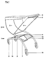
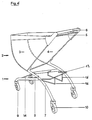
- the shopping cart shown in FIGS. 1 to 6 comprises a chassis 1, on the the goods container 2 is placed.
- the latter comprises two side walls 3, a rear wall 4 and a curved floor which merges into the front wall.
- the rear wall 4 of the goods container is suspended in the region of its upper edge 5 so that it can pivot about a horizontal axis, so that it can be pivoted upwards in a known manner for stacking several shopping carts.
- a handle bar 6 is provided in a known manner.
- the chassis 1 comprises two longitudinal sides, each of which consists of a rear spar 7 which runs obliquely forward and upward and a front spar 8 which is firmly connected to this approximately centrally and runs obliquely forward and downward.
- the front wheels 9 are arranged at the ends of the front spars 8, and the rear wheels 10 are arranged at the ends of the rear spars 7.
- the goods container 2 is suspended from the top of the rear spars 7.
- the two front spars 8 are connected to one another approximately in the middle of the chassis by means of the cross strut 11.
- a closed, trapezoidal support frame 12 is placed on top of this cross strut.
- the level in which the support frame is located 12 extends substantially perpendicular to the plane defined by the rear wall 4 of the goods container.
- a double cranked bracket 13 extends between the two rear spars 7 and is firmly connected to them.
- the plane defined by the offset runs slightly backwards, inclined downwards.
- a box tray is formed by the cross strut 11 including the support frame 12 and the bracket 13, into which a box can be inserted, inclined obliquely backwards, along the rear wall 4 of the goods container 2 from above until the bottom of the box rests on the support frame 12.
- the rear-facing wall of the box lies against the central section of the cranked bracket 13, while the side walls of the box are guided through the lateral sections of the bracket 13.
- the two front spars 8 are connected to each other near the front wheels 9 by means of a further cross strut 14.
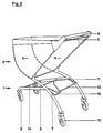
- the shopping cart according to FIG. 2 corresponds to that described above according to FIG. 1 with the exception of the different design of the edition for the box.
- a bracket 15 is fixedly connected to the cross strut 11, which initially extends essentially vertically downwards and after a bend obliquely backwards, downwards.
- a box received in the box storage generally stands with its bottom on the inclined area of the bracket; the cross strut 11 prevents it from sliding forward.
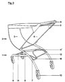
- the support of the crate storage is designed in such a way that cross strut 11 'is cranked.
- the overhang 16 initially runs essentially vertically downward in order to extend obliquely backwards and downwards after a bend. 3 corresponds to that according to FIG. 1, so that reference can be made to the corresponding explanations.
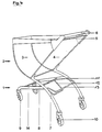
- the shopping cart according to FIG. 4 differs from that according to FIG. 1 in that the flat support frame 12 is open. It is also not placed on top of the cross strut 11, but rather is connected to it below it.
- the support frame 12 is also open and connected to the cross strut 11 below it.
- the support frame 12 is not flat, but rather cranked. It extends adjacent to the cross strut 11 initially essentially vertically downwards and only after it has been bent obliquely backwards-downwards.
- the shopping cart according to FIG. 6 does not have a cross strut connecting the front bars 8 of the chassis to one another.
- Two bracket segments 16 serve as the front holding element, the front ends of which are firmly connected approximately in the middle of the chassis to the front spars 8 and the rear ends of which are firmly connected to the cranked bracket 13 serving as an attachment for the box.
- the middle sections of the bracket segments 16 are inclined downwards and backwards; the bottom of a crate inserted into the crate shelf stands on them.
- the distance between the rear sections of the bracket segments 16 connected to the bracket 13 is less than the distance between the bracket segments in their front region; the middle sections of the two bracket segments 16, on which the box stands, thus converge towards one another towards the rear.
Abstract
Description
Die vorliegende Erfindung betrifft einen Einkaufswagen mit einem Fahrgestell und einem hierauf aufgesetzten Warenbehälter, wobei im hinteren Bereich des Einkaufswagens eine Kistenablage vorgesehen ist, welche zwei feststehende in Längsrichtung versetzt angeordnete Halteelemente für eine Kiste umfaßt, von denen das eine als Auflage für den Boden und das andere als Anlage für mindestens eine Wand einer aufzunehmenden Kiste dient.The present invention relates to a shopping cart with a chassis and a goods container placed thereon, in the rear area of the shopping cart a crate shelf is provided which comprises two fixed longitudinally offset holding elements for a crate, one of which serves as a support for the floor and the other serves as an attachment for at least one wall of a box to be accommodated.
Ein derartiger Einkaufswagen ist aus der deutschen Patentschrift 30 43 599 bekannt. Bei ihm sind als Halteelemente für die Kiste eine Querstrebe und ein Anschlag vorgesehen. Die Querstrebe, die als Auflage für die in der Kistenablage aufzunehmende Kiste dient, verbindet die Längsseiten des Fahrgestells im rückwärtigen unteren Bereich miteinander; und der Anschlag, welcher gemeinsam mit den seitlichen, den Korb stützenden Trägern als teilweise seitliche Begrenzung für die Kiste dient, ist vor der Querstrebe und auf einer anderen Höhe als diese angeordnet. Die bekannte Kistenablage ist somit nach hinten, entgegengesetzt zur Fahrtrichtung hin offen; eine Kiste wird von hinten her in die Ablage eingeschoben, bis sie am Anschlag anliegt. Dabei befindet sich die Kiste unter dem Warenbehälter und nimmt eine nach vorn, in Fahrtrichtung geneigte Lage ein.Such a shopping cart is known from German Patent 30 43 599. With him a cross strut and a stop are provided as holding elements for the box. The cross strut, which serves as a support for the crate to be accommodated in the crate storage, connects the long sides of the chassis to one another in the lower rear area; and the stop, which together with the side supports supporting the basket serves as a partial lateral boundary for the box, is arranged in front of the cross strut and at a different height than this. The known crate storage is thus open to the rear, opposite to the direction of travel; a box is placed in the storage area from behind inserted until it touches the stop. The box is located under the goods container and takes a position inclined towards the front in the direction of travel.
Ein Nachteil der bekannten Kistenablage besteht darin, daß Flaschen einer in der Kistenablage aufgenommenen Getränkekiste nicht zugänglich sind. Desweiteren ist die bekannte Kistenablage nur bei solchen Einkaufswagen realisierbar, bei denen genügend Raum unter dem Warenbehälter gegeben ist; bei Einkaufswagen mit einem tief heruntergezogenen Warenbehälter kann die bekannte Kistenablage hingegen nicht eingesetzt werden. Auch stellt das Einschieben einer schweren Kiste von hinten her unter den Warenbehälter des Einkaufswagens in gebeugter Stellung eine starke Belastung insbesondere des Rückens der entsprechenden Person dar.A disadvantage of the known crate rack is that bottles of a beverage crate accommodated in the crate rack are not accessible. Furthermore, the known crate storage can only be realized with shopping carts in which there is sufficient space under the goods container; in the case of shopping carts with a deeply pulled-down goods container, however, the known crate shelf cannot be used. The pushing in of a heavy box from behind under the goods container of the shopping cart in a bent position also places a heavy load on the back of the person in question.
Der vorliegenden Erfindung liegt die Aufgabe zugrunde, einen gattungsgemäßen Einkaufswagen zu schaffen, bei welchem die vorstehend genannten Nachteile nicht auftreten. Insbesondere soll ein Einkaufswagen geschaffen werden, bei welchem die Flaschen einer in der Kistenablage aufgenommenen Kiste von oben zugänglich sind, wobei die Kistenablage auch bei Einkaufswagen mit einem niedrig angeordneten Warenbehälter einsetzbar sein soll und wobei ferner die Beladung der Kistenablage mit einer schweren Kiste möglichst schonend für den Rücken der entsprechenden Person möglich ist.The present invention has for its object to provide a generic shopping cart in which the disadvantages mentioned above do not occur. In particular, a shopping cart is to be created in which the bottles of a box accommodated in the box rack are accessible from above, the box rack also being used in shopping carts with a low-lying goods container should be usable and the loading of the crate storage with a heavy crate is possible as gently as possible for the back of the person concerned.
Gemäß der vorliegenden Erfindung wird diese Aufgabe dadurch gelöst, daß das vordere Halteelement als Auflage für den Boden der Kiste und daß das hintere Halteelement nach hinten gekröpft und als Anlage für die beiden seitlichen und die hintere Wand der Kiste ausgebildet ist, so daß eine Kiste schräg nach hinten geneigt von oben in die Kistenablage einsetzbar ist und eine in die Kistenablage aufgenommene Kiste eine schräg nach hinten geneigte Stellung einnimmt. Die in der Kistenablage aufzunehmende Kiste wird somit nicht von hinten unter den Warenbehälter geschoben, sondern vielmehr von oben her an der Rückwand des Warenbehälters entlang in die Kistenablage eingesetzt. Die Kistenablage kann hierdurch höher angeordnet werden, als dies beim Stand der Technik der Fall ist, so daß eine Beladung der Kistenablage mit gestrecktem Rücken möglich ist. Zudem sind Flaschen, welche in einer in die Kistenablage eingesetzten Kiste aufgenommen sind, von oben her zugänglich; sie können somit der in der Kistenablage aufgenommenen Kiste nach oben entnommen werden, beispielsweise an der Kasse. Zudem kann beim Kauf verschiedener Getränke zunächst eine leere Kiste in die Kistenablage eingesetzt werden, welche nach und nach mit verschiedenen Flaschen gefüllt wird. Da sich die Kisten beim erfindungsgemäßen Einkaufswagen unbehindert hinter der Rückwand des Warenbehälters nach oben erstrecken können, lassen sich mit ihm auch dann hohe Kisten befördern, wenn der Warenbehälter relativ niedrig angeordnet ist.According to the present invention, this object is achieved in that the front holding element as a support for the bottom of the box and that the rear holding element is cranked rearward and designed as an attachment for the two side and the rear wall of the box, so that a box obliquely inclined backwards from above into the crate shelf and a crate accommodated in the crate shelf assumes an obliquely backward inclined position. The box to be accommodated in the box rack is therefore not pushed from behind under the goods container, but rather is inserted from above along the rear wall of the goods box into the box rack. As a result, the crate rack can be arranged higher than is the case in the prior art, so that loading of the crate rack with a stretched back is possible. In addition, bottles which are accommodated in a box inserted into the box storage area are accessible from above; they can thus be removed upwards from the box received in the box storage, for example at the checkout. In addition, when buying various drinks, an empty crate can first be inserted into the crate storage, which is gradually filled with different bottles. Since the boxes in the shopping cart according to the invention can extend freely behind the rear wall of the goods container, high boxes can also be transported with it if the goods container is arranged relatively low.
Das vordere, als Auflage für den Boden der Kiste dienende Halteelement kann bevorzugt eine die beiden Längsseiten des Fahrgestells verbindende Querstrebe umfassen. Im Falle einer gerade verlaufenden Querstrebe ist an dieser zweckmäßigerweise ein schräg nach hinten, unten geneigtes Tragelement vorgesehen, welches den Boden der aufzunehmenden Kiste unterstützt. Hierdurch lassen sich Kisten verschiedener Abmessungen transportieren.The front holding element, which serves as a support for the bottom of the box, can preferably comprise a cross strut connecting the two long sides of the chassis. In the case of a straight cross strut, a support element which is inclined obliquely backwards and downwards is expediently provided on this, which supports the bottom of the box to be accommodated. This allows boxes of different dimensions to be transported.
Zumindest derjenige Bereich des an der Querstrebe angeordneten Tragelements, der den Boden der Kiste unterstützt, erstreckt sich bevorzugt in einer Ebene, welche in etwa rechtwinklig zur Rückwand des Warenbehälters des Einkaufswagens verläuft. Hierdurch wird der hinter der Rückwand zur Verfügung stehende Raum optimal genutzt, so daß eine in die Kistenablage eingesetzte Kiste keine Behinderung darstellt.At least that area of the support element arranged on the cross strut, which supports the bottom of the box, preferably extends in a plane which is approximately at right angles to the rear wall of the goods container of the shopping trolley. This makes the one available behind the rear wall Space optimally used so that a box inserted in the box storage does not represent a hindrance.
Ein derartiges Tragelement kann beispielsweise als oberhalb oder unterhalb der Querstrebe auf diese aufgesetzter, offener oder geschlossener Auflagerahmen ausgebildet sein. Alternativ hierzu ist denkbar, daß an der Querstrebe ein Bügel vorgesehen ist, der insbesondere in der Weise abgewinkelt sein kann, daß er sich von der Querstrebe zunächst im wesentlichen nach unten und nach einer Abknickung schräg nach hinten, unten erstreckt; unterschiedlich große Kisten können dann allein auf dem Bügel, auf dem Bügel und der Querstrebe oder allein auf der Querstrebe ruhen und so optimal in der Kistenablage aufgenommen werden. Zudem kann die Querstrebe, wenn die Kiste auf dem Bügel aufsteht, zur Sicherung der Kiste gegen Verrutschen nach vorn dienen. Die Querstrebe kann bei sämtlichen vorstehend skizzierten Varianten eine nach oben gerichtete Auskröpfung aufweisen, die als Anschlag für die aufzunehmende Kiste gegen Verrutschen nach vorn dient.Such a support element can be designed, for example, as an open or closed support frame placed above or below the cross strut. As an alternative to this, it is conceivable that a bracket is provided on the cross strut, which can in particular be angled in such a way that it initially extends essentially downwards from the cross strut and, after a bend, obliquely backwards and downwards; boxes of different sizes can then rest alone on the bracket, on the bracket and the cross strut or alone on the cross strut and thus be optimally accommodated in the crate storage. In addition, when the box stands on the bracket, the cross strut can serve to secure the box against slipping forward. In all of the variants outlined above, the cross strut can have an upwardly directed offset, which serves as a stop for the box to be accommodated to prevent it from slipping forward.
Anstelle einer gerade verlaufenden Querstrebe kann jedoch auch eine doppelt nach hinten gekröpft ausgebildete vorgesehen sein. In diesem Falle steht die Kiste mit ihrem Boden auf der Kröpfung der Querstrebe auf. Auch hier kann die Kröpfung zunächst nach unten und nach einer Abwinklung schräg nach hinten unten verlaufen, um die Kiste gegen Verrutschen nach vorn zu sichern.Instead of a straight cross strut, a double cranked back can also be provided. In In this case, the crate stands with its bottom on the crank of the cross strut. Here, too, the cranking can initially run downwards and, after being bent, backwards at an angle to secure the box against slipping forward.
Auch wenn es zur Austeifung des Fahrgestells zweckmäßig ist, daß das vordere Halteelement als die beiden Längsseiten des Fahrgestells miteinander verbindende Querstrebe ausgebildet ist, ist dies jedoch keineswegs zwingend erforderlich. Vielmehr kann das vordere Halteelement auch aus zwei getrennten, jeweils an einer Längsseite des Fahrgestells angeordneten Halteelementsegmenten bestehen. Diese können ggfs. zusätzlich mit dem hinteren, als Anlage dienenden Halteelement verbunden sein.Even if it is expedient for the bracing of the chassis that the front holding element is designed as a cross strut connecting the two long sides of the chassis, this is in no way absolutely necessary. Rather, the front holding element can also consist of two separate holding element segments each arranged on a long side of the chassis. If necessary, these can additionally be connected to the rear holding element serving as an attachment.
Das hintere, als Anlage für die Kiste dienende Halteelement ist zweckmäßigerweise als die Längsseiten des Fahrgestells verbindender, nach hinten ausgekröpfter Bügel ausgebildet. Durch die Auskröpfung wird einerseits erreicht, daß die Kiste relativ weit hinten am Einkaufswagen ruht, was die Beladung der Kistenablage von oben her erheblich vereinfacht. Zudem stellt die Kröpfung des Bügels eine zuverlässige Führung der Kiste und Sicherung gegen Verrutschen dar.The rear holding element, which serves as an attachment for the crate, is expediently designed as a bracket that connects to the long sides of the chassis and is cranked out to the rear. The overhanging on the one hand ensures that the crate rests relatively far back on the shopping cart, which considerably simplifies loading the crate storage from above. In addition, the bow of the bracket provides a reliable Guide the box and secure against slipping.
Bei einem Einkaufswagen, bei dem jede Längsseite des Fahrgestells einen schräg nach vorn, oben verlaufenden Hinterholm und einen schräg nach vorn, unten verlaufenden Vorderholm umfaßt, läßt sich die Erfindung mit besonderem Vorteil anwenden. Denn hier kann die Querstrebe auf einer optimalen Höhe zwischen den beiden Vorderholmen, diese miteinander verbindend vorgesehen sein; und der gekröpft ausgebildete, als Anlage dienende Bügel kann die beiden Hinterholme des Fahrgestells miteinander verbinden. Bevorzugt ist dabei die Querstrebe etwa in der Mitte des Fahrgestells angeordnet.The invention can be used with particular advantage in a shopping cart in which each long side of the chassis comprises a rear spar that runs obliquely forward and upward and a front spar that runs obliquely forward and downward. Because here the cross strut can be provided at an optimal height between the two front spars, connecting them to each other; and the cranked, serving as a bracket can connect the two rear spars of the chassis. The cross strut is preferably arranged approximately in the middle of the chassis.
Im folgenden wird die Erfindung anhand der Zeichnung näher erläutert. Es zeigt
- Fig. 1
- eine Ansicht von schräg hinten auf eine erste bevorzugte Ausführungsform und,
- Fig. 2
- bis 6 fünf weitere bevorzugte Ausführungsformen des erfindungsgemäßen Einkaufswagens.
- Fig. 1
- a view obliquely from behind of a first preferred embodiment and
- Fig. 2
- to 6 five further preferred embodiments of the shopping cart according to the invention.
Der in den Fig. 1 bis 6 wiedergegebene Einkaufswagen umfaßt ein Fahrgestell 1, auf das der Warenbehälter 2 aufgesetzt ist. Letzterer umfaßt zwei Seitenwände 3, eine Rückwand 4 sowie einen gekrümmten, in die Vorderwand übergehenden Boden. Die Rückwand 4 des Warenbehälters ist im Bereich ihrer Oberkante 5 um eine horizontale Achse verschwenkbar aufgehängt, so daß sie zum Stapeln mehrerer Einkaufswagen in bekannter Weise nach oben verschwenkt werden kann. Am rückwärtigen oberen Ende des Warenbehälters 2 ist in bekannter Weise eine Griffstange 6 vorgesehen.The shopping cart shown in FIGS. 1 to 6 comprises a
Das Fahrgestell 1 umfaßt zwei Längsseiten, von denen jede aus einem schräg nach vorne, oben verlaufenden Hinterholm 7 und einem mit diesem etwa mittig fest verbundenen, schräg nach vorne, unten verlaufenden Vorderholm 8 besteht. Endseitig an den Vorderholmen 8 sind die Vorderräder 9 angeordnet, und endseitig an den Hinterholmen 7 die Hinterräder 10. Der Warenbehälter 2 ist oben an den Hinterholmen 7 aufgehängt.The
Gemäß Fig. 1 sind die beiden Vorderholme 8 etwa in der Mitte des Fahrgestells mittels der Querstrebe 11 miteinander verbunden. Auf diese Querstrebe ist oben ein geschlossener, trapezförmiger Auflagerahmen 12 aufgesetzt. Die Ebene, in welcher sich der Auflagerahmen 12 erstreckt, verläuft im wesentlichen senkrecht zu der durch die Rückwand 4 des Warenbehälters definierten Ebene.1, the two
Ein zweifach gekröpfter Bügel 13 erstreckt sich zwischen den beiden Hinterholmen 7 und ist mit diesen fest verbunden. Die durch die Kröpfung definierte Ebene verläuft leicht nach hinten, unten geneigt.A double cranked
Durch die Querstrebe 11 samt Auflagerahmen 12 sowie den Bügel 13 wird eine Kistenablage gebildet, in welche eine Kiste schräg nach hinten geneigt entlang der Rückwand 4 des Warenbehälters 2 von oben her eingesetzt werden kann, bis der Boden der Kiste auf den Auflagerahmen 12 aufsitzt. Die nach hinten weisende Wand der Kiste liegt an dem mittleren Abschnitt des gekröpften Bügels 13 an, während die Seitenwände der Kiste durch die seitlichen Abschnitte des Bügels 13 geführt werden.A box tray is formed by the
Zur Aussteifung des Fahrgestells sind die beiden Vorderholme 8 nahe den Vorderrädern 9 mittels einer weiteren Querstrebe 14 miteinander verbunden.To stiffen the chassis, the two
Der Einkaufswagen gemäß Fig. 2 entspricht dem vorstehend beschriebenen gemäß Fig. 1 mit Ausnahme der andersartigen Gestaltung der Auflage für die Kiste. Und zwar ist mit der Querstrebe 11 ein Bügel 15 fest verbunden, der sich zunächst im wesentlichen vertikal nach unten und nach einer Abknickung schräg nach hinten, unten erstreckt. Eine in der Kistenablage aufgenommene Kiste steht i. a. mit ihrem Boden auf dem geneigten Bereich des Bügels auf; durch die Querstrebe 11 ist sie daran gehindert, nach vorne zu verrutschen.The shopping cart according to FIG. 2 corresponds to that described above according to FIG. 1 with the exception of the different design of the edition for the box. Namely, a
Gemäß Fig. 3 ist die Auflage der Kistenablage in der Weise ausgestaltet, daß Querstrebe 11' gekröpft ausgebildet ist. Die Auskröpfung 16 verläuft zunächst im wesentlichen vertikal nach unten, um sich nach einer Abknickung schräg nach hinten, unten zu erstrecken. Im übrigen entspricht der Einkaufswagen gemäß Fig. 3 demjenigen gemäß Fig. 1, so daß auf die entsprechenden Erläuterungen verwiesen werden kann.According to Fig. 3, the support of the crate storage is designed in such a way that cross strut 11 'is cranked. The
Der Einkaufswagen gemäß Fig. 4 unterscheidet sich von demjenigen gemäß Fig. 1 dadurch, daß der ebene Auflagerahmen 12 offen ausgebildet ist. Er ist zudem nicht oben auf die Querstrebe 11 aufgesetzt, sondern vielmehr unterhalb dieser mit ihr verbunden.The shopping cart according to FIG. 4 differs from that according to FIG. 1 in that the
Bei dem Einkaufswagen gemäß Fig. 5 ist der Auflagerahmen 12 ebenfalls offen ausgebildet und unterhalb der Querstrebe 11 mit dieser verbunden. Anders als bei dem Einkaufswagen gemäß Fig. 4 ist der Auflagerahmen 12 jedoch nicht eben, sondern vielmehr gekröpft ausgebildet. Er erstreckt sich benachbart der Querstrebe 11 zunächst im wesentlichen vertikal nach unten und erst nach einer Abknickung schräg nach hinten-unten.5, the
Der Einkaufswagen gemäß Fig. 6 weist keine die Vorderholme 8 des Fahrgestells miteinander verbindende Querstrebe auf. Als vorderes Halteelement dienen zwei Bügelsegmente 16, deren vordere Enden etwa in der Mitte des Fahrgestells mit den Vorderholmen 8 und deren hintere Enden mit dem gekröpften, als Anlage für die Kiste dienenden Bügel 13 fest verbunden sind. Die mittleren Abschnitte der Bügelsegmente 16 sind schräg nach unten-hinten geneigt; auf ihnen steht der Boden einer in die Kistenablage eingesetzten Kiste auf. Um das Stapeln mehrerer Einkaufswagen nicht zu behindern, ist der Abstand zwischen den hinteren, mit dem Bügel 13 verbundenen Abschnitten der Bügelsegmente 16 geringer als der Abstand zwischen den Bügelsegmenten in ihrem vorderen Bereich; die mittleren Abschnitte der beiden Bügelsegmente 16, auf denen die Kiste aufsteht, konvergieren somit nach hinten gegeneinander.The shopping cart according to FIG. 6 does not have a cross strut connecting the
Claims (10)
dadurch gekennzeichnet,
daß das vordere Halteelement als Auflage für den Boden der Kiste und daß das hintere Halteelement gekröpft und als Anlage für die beiden seitlichen und die hintere Wand der Kiste ausgebildet ist, so daß eine Kiste schräg nach hinten geneigt von oben in die Kistenablage einsetzbar ist und eine in der Kistenablage aufgenommene Kiste eine schräg nach hinten geneigte Stellung einnimmt.Shopping cart with a chassis (1) and a goods container (2) placed thereon, a crate shelf being provided in the rear area of the shopping trolley, which comprises two fixed, longitudinally offset holding elements for a crate, one of which serves as a support for the floor and the other serves as an attachment for at least one wall of a box to be accommodated,
characterized,
that the front holding element as a support for the bottom of the box and that the rear holding element is cranked and designed as an attachment for the two side and the rear wall of the box, so that a box inclined obliquely backwards can be inserted into the box storage from above and one in the crate storage box takes an inclined position inclined backwards.
dadurch gekennzeichnet,
daß das vordere Halteelement eine die beiden Längsseiten des Fahrgestells verbindende Querstrebe (11, 11') umfaßt.Shopping cart according to claim 1,
characterized,
that the front holding element comprises a cross strut (11, 11 ') connecting the two long sides of the chassis.
dadurch gekennzeichnet,
daß die Querstrebe (11) sich gerade zwischen den beiden Längsseiten des Fahrgestells erstreckt, wobei mit ihr ein Auflagerahmen (12) verbunden ist, der zumindest bereichsweise schräg nach hinten, unten geneigt ist.Shopping cart according to claim 2,
characterized,
that the cross strut (11) extends straight between the two longitudinal sides of the chassis, with which a support frame (12) is connected, which is inclined at least in regions obliquely backwards, downwards.
dadurch gekennzeichnet,
daß die Querstrebe (11) sich gerade zwischen den beiden Längsseiten des Fahrgestells erstreckt, wobei mit ihr ein Bügel (15) verbunden ist, der zunächst im wesentlichen vertikal nach unten und nach einer Abknickung in einer schräg nach hinten, unten geneigten Ebene verläuft.Shopping cart according to claim 2,
characterized,
that the cross strut (11) extends straight between the two longitudinal sides of the chassis, with which a bracket (15) is connected, which initially runs essentially vertically downwards and after a bend in an obliquely backward, downwardly inclined plane.
dadurch gekennzeichnet,
daß die Querstrebe (11') gekröpft ausgebildet ist mit einer schräg nach unten, hinten vorspringenden Auskröpfung (16).Shopping cart according to claim 2,
characterized,
that the cross strut (11 ') is cranked with an obliquely downward, rearward protrusion (16).
dadurch gekennzeichnet,
daß der Auflagerahmen (12), der Bügel (15) bzw. die Auskröpfung (16) sich zumindest bereichsweise in einer Ebene erstreckt, welche im wesentlichen senkrecht zu der durch die Rückwand (4) des Warenbehälters (2) definierten Ebene verläuft.Shopping cart according to one of claims 3 to 5,
characterized,
that the support frame (12), the bracket (15) or the overhang (16) extends at least in regions in a plane which is substantially perpendicular to the plane defined by the rear wall (4) of the goods container (2).
dadurch gekennzeichnet,
daß das vordere Halteelement zwei getrennte, jeweils an einer Längsseite des Fahrgestells angeordnete Halteelementsegmente (16) umfaßt.Shopping cart according to claim 1,
characterized,
that the front holding element comprises two separate holding element segments (16), each arranged on a longitudinal side of the chassis.
dadurch gekennzeichnet,
daß das hintere Halteelement als die Längsseiten des Fahrgestells verbindender, nach hinten ausgekröpfter Bügel (13) ausgebildet ist.Shopping cart according to claim 1,
characterized,
that the rear holding element is designed as a bracket (13) which is offset to the rear and connects the longitudinal sides of the chassis.
dadurch gekennzeichnet,
daß jede Längsseite des Fahrgestells einen schräg nach vorne, oben verlaufenden Hinterholm (7) und einen schräg nach vorne, unten verlaufenden Vorderholm (8) umfaßt, wobei die Querstrebe (11) die beiden Vorderholme (8) und der Bügel (13) die beiden Hinterholme (7) miteinander verbindet.Shopping cart according to claim 2 and claim 8,
characterized,
that each longitudinal side of the chassis comprises an obliquely forward, upward rear spar (7) and an obliquely forward, downward front spar (8), the cross strut (11) the two front spars (8) and the bracket (13) connects the two rear spars (7).
dadurch gekennzeichnet,
daß die Querstrebe (11) im wesentlichen in der Mitte des Fahrgestells (1) angeordnet ist.Shopping cart according to claim 9,
characterized,
that the cross strut (11) is arranged substantially in the middle of the chassis (1).
Applications Claiming Priority (2)
| Application Number | Priority Date | Filing Date | Title |
|---|---|---|---|
| DE4303087A DE4303087A1 (en) | 1993-02-04 | 1993-02-04 | Shopping venture |
| DE4303087 | 1993-02-04 |
Publications (2)
| Publication Number | Publication Date |
|---|---|
| EP0609663A1 true EP0609663A1 (en) | 1994-08-10 |
| EP0609663B1 EP0609663B1 (en) | 1997-07-09 |
Family
ID=6479561
Family Applications (1)
| Application Number | Title | Priority Date | Filing Date |
|---|---|---|---|
| EP94100326A Expired - Lifetime EP0609663B1 (en) | 1993-02-04 | 1994-01-12 | Shopping trolley |
Country Status (3)
| Country | Link |
|---|---|
| EP (1) | EP0609663B1 (en) |
| AT (1) | ATE155091T1 (en) |
| DE (2) | DE4303087A1 (en) |
Cited By (3)
| Publication number | Priority date | Publication date | Assignee | Title |
|---|---|---|---|---|
| EP0731011A1 (en) * | 1995-03-08 | 1996-09-11 | Brüder Siegel GmbH + Co. KG Draht- und Metallwarenfabrik | Shopping trolley |
| EP0751057A1 (en) * | 1995-06-27 | 1997-01-02 | Wanzl Metallwarenfabrik Gmbh | Nestable shopping trolley |
| EP1182113A3 (en) * | 2000-08-19 | 2003-11-12 | Wanzl Metallwarenfabrik Gmbh | Shopping cart for a person using a wheelchair |
Families Citing this family (3)
| Publication number | Priority date | Publication date | Assignee | Title |
|---|---|---|---|---|
| DE19813685A1 (en) * | 1998-03-27 | 1999-09-30 | Siegel Geb Gmbh Co Kg | Stackable shopping cart |
| DE202018000559U1 (en) | 2018-02-03 | 2019-01-07 | Surim Eberlein | Hand-operated transport trolley for the purchase of goods |
| DE202020104671U1 (en) | 2020-08-12 | 2021-11-15 | Wanzl GmbH & Co. KGaA | Underframe and trolley |
Citations (3)
| Publication number | Priority date | Publication date | Assignee | Title |
|---|---|---|---|---|
| DE3043599A1 (en) * | 1980-11-19 | 1982-06-24 | Rudolf Wanzl Kg, 8874 Leipheim | Supermarket shopping trolley assembly - has forward cross wire fitted between basket support posts so that it forms loading place for case of drinks |
| DE3444969A1 (en) * | 1984-12-10 | 1986-06-12 | Rudolf Wanzl Kg, 8874 Leipheim | Stackable shopping trolley |
| EP0491595A1 (en) * | 1990-12-18 | 1992-06-24 | Ateliers Reunis Caddie | Shopping trolly of the nestable type comprising a carrier basket and means for supporting a box or other goods |
Family Cites Families (2)
| Publication number | Priority date | Publication date | Assignee | Title |
|---|---|---|---|---|
| US3309100A (en) * | 1963-10-10 | 1967-03-14 | Steiner Spa Karl | Carriage for the conveyance of goods in bulk, chiefly intended for supermarkets and the like |
| FR2642718B1 (en) * | 1989-02-03 | 1991-04-12 | Caddie Atel Reunis | PROCESS FOR THE REPLACEMENT OF GOODS PURCHASED WITHIN A PURCHASED CARRIAGE AFTER THEIR CHECK-OUT, AND EQUIPMENT OF A STORE FOR THE IMPLEMENTATION OF THIS PROCESS |
-
1993
- 1993-02-04 DE DE4303087A patent/DE4303087A1/en not_active Withdrawn
-
1994
- 1994-01-12 EP EP94100326A patent/EP0609663B1/en not_active Expired - Lifetime
- 1994-01-12 AT AT94100326T patent/ATE155091T1/en not_active IP Right Cessation
- 1994-01-12 DE DE59403264T patent/DE59403264D1/en not_active Expired - Fee Related
Patent Citations (3)
| Publication number | Priority date | Publication date | Assignee | Title |
|---|---|---|---|---|
| DE3043599A1 (en) * | 1980-11-19 | 1982-06-24 | Rudolf Wanzl Kg, 8874 Leipheim | Supermarket shopping trolley assembly - has forward cross wire fitted between basket support posts so that it forms loading place for case of drinks |
| DE3444969A1 (en) * | 1984-12-10 | 1986-06-12 | Rudolf Wanzl Kg, 8874 Leipheim | Stackable shopping trolley |
| EP0491595A1 (en) * | 1990-12-18 | 1992-06-24 | Ateliers Reunis Caddie | Shopping trolly of the nestable type comprising a carrier basket and means for supporting a box or other goods |
Cited By (3)
| Publication number | Priority date | Publication date | Assignee | Title |
|---|---|---|---|---|
| EP0731011A1 (en) * | 1995-03-08 | 1996-09-11 | Brüder Siegel GmbH + Co. KG Draht- und Metallwarenfabrik | Shopping trolley |
| EP0751057A1 (en) * | 1995-06-27 | 1997-01-02 | Wanzl Metallwarenfabrik Gmbh | Nestable shopping trolley |
| EP1182113A3 (en) * | 2000-08-19 | 2003-11-12 | Wanzl Metallwarenfabrik Gmbh | Shopping cart for a person using a wheelchair |
Also Published As
| Publication number | Publication date |
|---|---|
| ATE155091T1 (en) | 1997-07-15 |
| DE59403264D1 (en) | 1997-08-14 |
| DE4303087A1 (en) | 1994-08-11 |
| EP0609663B1 (en) | 1997-07-09 |
Similar Documents
| Publication | Publication Date | Title |
|---|---|---|
| DE19526708A1 (en) | Shopping cart and container system | |
| EP0141398B1 (en) | Nestable shopping trolley | |
| DE3448335C3 (en) | Stackable shopping cart | |
| DE4337917C2 (en) | Stackable shopping cart | |
| EP0609663B1 (en) | Shopping trolley | |
| EP0672569B1 (en) | Shopping trolley | |
| DE8136236U1 (en) | STACKABLE SHOPPING CART | |
| DE3208691C2 (en) | ||
| EP0751057B1 (en) | Nestable shopping trolley | |
| DE102005013018B3 (en) | Shopping trolley, e.g. for supermarket, has a resting shelf with receiving region for small objects such as shrink-wrapped bottle packs | |
| EP0738645B1 (en) | Nestable shopping trolley | |
| DE3444256C2 (en) | Stackable shopping cart | |
| DE3043599C2 (en) | ||
| EP0676323B1 (en) | Nestable shopping trolley | |
| DE2505910A1 (en) | Movable foldable goods container - has sidewalls front wall and floor folding into space formed by U-shaped rear wall | |
| EP0945326A2 (en) | Nestable shopping trolley | |
| DE4436804A1 (en) | Shopping trolley | |
| DE4312392A1 (en) | Shopping venture | |
| EP0734933B1 (en) | Nestable shopping trolley | |
| EP0392335B1 (en) | Stackable shopping trolley | |
| EP0731011B1 (en) | Shopping trolley | |
| EP0474097B1 (en) | Shopping trolley for self-service shops | |
| DE7626532U1 (en) | SHOPPING CART WITH FOLDING SHELF | |
| DE8206722U1 (en) | SHOPPING CART WITH STORAGE | |
| EP3747729A1 (en) | Transport trolley |
Legal Events
| Date | Code | Title | Description |
|---|---|---|---|
| PUAI | Public reference made under article 153(3) epc to a published international application that has entered the european phase |
Free format text: ORIGINAL CODE: 0009012 |
|
| AK | Designated contracting states |
Kind code of ref document: A1 Designated state(s): AT BE CH DE ES FR GB IT LI LU NL |
|
| 17P | Request for examination filed |
Effective date: 19940728 |
|
| 17Q | First examination report despatched |
Effective date: 19950614 |
|
| GRAG | Despatch of communication of intention to grant |
Free format text: ORIGINAL CODE: EPIDOS AGRA |
|
| GRAH | Despatch of communication of intention to grant a patent |
Free format text: ORIGINAL CODE: EPIDOS IGRA |
|
| GRAH | Despatch of communication of intention to grant a patent |
Free format text: ORIGINAL CODE: EPIDOS IGRA |
|
| GRAA | (expected) grant |
Free format text: ORIGINAL CODE: 0009210 |
|
| AK | Designated contracting states |
Kind code of ref document: B1 Designated state(s): AT BE CH DE ES FR GB IT LI LU NL |
|
| PG25 | Lapsed in a contracting state [announced via postgrant information from national office to epo] |
Ref country code: NL Free format text: LAPSE BECAUSE OF FAILURE TO SUBMIT A TRANSLATION OF THE DESCRIPTION OR TO PAY THE FEE WITHIN THE PRESCRIBED TIME-LIMIT Effective date: 19970709 Ref country code: ES Free format text: THE PATENT HAS BEEN ANNULLED BY A DECISION OF A NATIONAL AUTHORITY Effective date: 19970709 |
|
| REF | Corresponds to: |
Ref document number: 155091 Country of ref document: AT Date of ref document: 19970715 Kind code of ref document: T |
|
| REG | Reference to a national code |
Ref country code: CH Ref legal event code: EP |
|
| REF | Corresponds to: |
Ref document number: 59403264 Country of ref document: DE Date of ref document: 19970814 |
|
| GBT | Gb: translation of ep patent filed (gb section 77(6)(a)/1977) |
Effective date: 19970813 |
|
| ITF | It: translation for a ep patent filed |
Owner name: BARZANO'E ZANARDO S.P.A. |
|
| ET | Fr: translation filed | ||
| NLV1 | Nl: lapsed or annulled due to failure to fulfill the requirements of art. 29p and 29m of the patents act | ||
| PG25 | Lapsed in a contracting state [announced via postgrant information from national office to epo] |
Ref country code: LU Free format text: LAPSE BECAUSE OF NON-PAYMENT OF DUE FEES Effective date: 19980112 |
|
| PG25 | Lapsed in a contracting state [announced via postgrant information from national office to epo] |
Ref country code: LI Free format text: LAPSE BECAUSE OF NON-PAYMENT OF DUE FEES Effective date: 19980131 Ref country code: CH Free format text: LAPSE BECAUSE OF NON-PAYMENT OF DUE FEES Effective date: 19980131 Ref country code: BE Free format text: LAPSE BECAUSE OF NON-PAYMENT OF DUE FEES Effective date: 19980131 |
|
| PLBE | No opposition filed within time limit |
Free format text: ORIGINAL CODE: 0009261 |
|
| STAA | Information on the status of an ep patent application or granted ep patent |
Free format text: STATUS: NO OPPOSITION FILED WITHIN TIME LIMIT |
|
| 26N | No opposition filed | ||
| BERE | Be: lapsed |
Owner name: BRUDER SIEGEL G.M.B.H. + CO. K.G. DRAHT- UND META Effective date: 19980131 |
|
| REG | Reference to a national code |
Ref country code: CH Ref legal event code: PL |
|
| REG | Reference to a national code |
Ref country code: GB Ref legal event code: IF02 |
|
| PGFP | Annual fee paid to national office [announced via postgrant information from national office to epo] |
Ref country code: FR Payment date: 20060119 Year of fee payment: 13 |
|
| PGFP | Annual fee paid to national office [announced via postgrant information from national office to epo] |
Ref country code: AT Payment date: 20060123 Year of fee payment: 13 Ref country code: GB Payment date: 20060123 Year of fee payment: 13 |
|
| PGFP | Annual fee paid to national office [announced via postgrant information from national office to epo] |
Ref country code: DE Payment date: 20060327 Year of fee payment: 13 |
|
| PG25 | Lapsed in a contracting state [announced via postgrant information from national office to epo] |
Ref country code: DE Free format text: LAPSE BECAUSE OF NON-PAYMENT OF DUE FEES Effective date: 20070801 |
|
| GBPC | Gb: european patent ceased through non-payment of renewal fee |
Effective date: 20070112 |
|
| REG | Reference to a national code |
Ref country code: FR Ref legal event code: ST Effective date: 20070930 |
|
| PG25 | Lapsed in a contracting state [announced via postgrant information from national office to epo] |
Ref country code: GB Free format text: LAPSE BECAUSE OF NON-PAYMENT OF DUE FEES Effective date: 20070112 Ref country code: AT Free format text: LAPSE BECAUSE OF NON-PAYMENT OF DUE FEES Effective date: 20070112 |
|
| PGFP | Annual fee paid to national office [announced via postgrant information from national office to epo] |
Ref country code: IT Payment date: 20070504 Year of fee payment: 14 |
|
| PG25 | Lapsed in a contracting state [announced via postgrant information from national office to epo] |
Ref country code: FR Free format text: LAPSE BECAUSE OF NON-PAYMENT OF DUE FEES Effective date: 20070131 |
|
| PG25 | Lapsed in a contracting state [announced via postgrant information from national office to epo] |
Ref country code: IT Free format text: LAPSE BECAUSE OF NON-PAYMENT OF DUE FEES Effective date: 20080112 |