EP0441963A1 - Absoluter wertkodierer - Google Patents
Absoluter wertkodierer Download PDFInfo
- Publication number
- EP0441963A1 EP0441963A1 EP90901883A EP90901883A EP0441963A1 EP 0441963 A1 EP0441963 A1 EP 0441963A1 EP 90901883 A EP90901883 A EP 90901883A EP 90901883 A EP90901883 A EP 90901883A EP 0441963 A1 EP0441963 A1 EP 0441963A1
- Authority
- EP
- European Patent Office
- Prior art keywords
- code
- numbers
- sequence
- codes
- bit
- Prior art date
- Legal status (The legal status is an assumption and is not a legal conclusion. Google has not performed a legal analysis and makes no representation as to the accuracy of the status listed.)
- Withdrawn
Links
- 238000000034 method Methods 0.000 claims description 23
- 238000010586 diagram Methods 0.000 description 3
- 230000007704 transition Effects 0.000 description 2
- 230000003287 optical effect Effects 0.000 description 1
Images


Classifications
-
- G—PHYSICS
- G01—MEASURING; TESTING
- G01D—MEASURING NOT SPECIALLY ADAPTED FOR A SPECIFIC VARIABLE; ARRANGEMENTS FOR MEASURING TWO OR MORE VARIABLES NOT COVERED IN A SINGLE OTHER SUBCLASS; TARIFF METERING APPARATUS; MEASURING OR TESTING NOT OTHERWISE PROVIDED FOR
- G01D5/00—Mechanical means for transferring the output of a sensing member; Means for converting the output of a sensing member to another variable where the form or nature of the sensing member does not constrain the means for converting; Transducers not specially adapted for a specific variable
- G01D5/12—Mechanical means for transferring the output of a sensing member; Means for converting the output of a sensing member to another variable where the form or nature of the sensing member does not constrain the means for converting; Transducers not specially adapted for a specific variable using electric or magnetic means
- G01D5/244—Mechanical means for transferring the output of a sensing member; Means for converting the output of a sensing member to another variable where the form or nature of the sensing member does not constrain the means for converting; Transducers not specially adapted for a specific variable using electric or magnetic means influencing characteristics of pulses or pulse trains; generating pulses or pulse trains
- G01D5/249—Mechanical means for transferring the output of a sensing member; Means for converting the output of a sensing member to another variable where the form or nature of the sensing member does not constrain the means for converting; Transducers not specially adapted for a specific variable using electric or magnetic means influencing characteristics of pulses or pulse trains; generating pulses or pulse trains using pulse code
-
- H—ELECTRICITY
- H03—ELECTRONIC CIRCUITRY
- H03M—CODING; DECODING; CODE CONVERSION IN GENERAL
- H03M1/00—Analogue/digital conversion; Digital/analogue conversion
- H03M1/12—Analogue/digital converters
- H03M1/22—Analogue/digital converters pattern-reading type
- H03M1/24—Analogue/digital converters pattern-reading type using relatively movable reader and disc or strip
- H03M1/28—Analogue/digital converters pattern-reading type using relatively movable reader and disc or strip with non-weighted coding
- H03M1/282—Analogue/digital converters pattern-reading type using relatively movable reader and disc or strip with non-weighted coding of the pattern-shifting type, e.g. pseudo-random chain code
-
- G—PHYSICS
- G01—MEASURING; TESTING
- G01D—MEASURING NOT SPECIALLY ADAPTED FOR A SPECIFIC VARIABLE; ARRANGEMENTS FOR MEASURING TWO OR MORE VARIABLES NOT COVERED IN A SINGLE OTHER SUBCLASS; TARIFF METERING APPARATUS; MEASURING OR TESTING NOT OTHERWISE PROVIDED FOR
- G01D5/00—Mechanical means for transferring the output of a sensing member; Means for converting the output of a sensing member to another variable where the form or nature of the sensing member does not constrain the means for converting; Transducers not specially adapted for a specific variable
- G01D5/12—Mechanical means for transferring the output of a sensing member; Means for converting the output of a sensing member to another variable where the form or nature of the sensing member does not constrain the means for converting; Transducers not specially adapted for a specific variable using electric or magnetic means
- G01D5/244—Mechanical means for transferring the output of a sensing member; Means for converting the output of a sensing member to another variable where the form or nature of the sensing member does not constrain the means for converting; Transducers not specially adapted for a specific variable using electric or magnetic means influencing characteristics of pulses or pulse trains; generating pulses or pulse trains
- G01D5/249—Mechanical means for transferring the output of a sensing member; Means for converting the output of a sensing member to another variable where the form or nature of the sensing member does not constrain the means for converting; Transducers not specially adapted for a specific variable using electric or magnetic means influencing characteristics of pulses or pulse trains; generating pulses or pulse trains using pulse code
- G01D5/2492—Pulse stream
- G01D5/2495—Pseudo-random code
-
- G—PHYSICS
- G01—MEASURING; TESTING
- G01D—MEASURING NOT SPECIALLY ADAPTED FOR A SPECIFIC VARIABLE; ARRANGEMENTS FOR MEASURING TWO OR MORE VARIABLES NOT COVERED IN A SINGLE OTHER SUBCLASS; TARIFF METERING APPARATUS; MEASURING OR TESTING NOT OTHERWISE PROVIDED FOR
- G01D5/00—Mechanical means for transferring the output of a sensing member; Means for converting the output of a sensing member to another variable where the form or nature of the sensing member does not constrain the means for converting; Transducers not specially adapted for a specific variable
- G01D5/26—Mechanical means for transferring the output of a sensing member; Means for converting the output of a sensing member to another variable where the form or nature of the sensing member does not constrain the means for converting; Transducers not specially adapted for a specific variable characterised by optical transfer means, i.e. using infrared, visible, or ultraviolet light
- G01D5/32—Mechanical means for transferring the output of a sensing member; Means for converting the output of a sensing member to another variable where the form or nature of the sensing member does not constrain the means for converting; Transducers not specially adapted for a specific variable characterised by optical transfer means, i.e. using infrared, visible, or ultraviolet light with attenuation or whole or partial obturation of beams of light
- G01D5/34—Mechanical means for transferring the output of a sensing member; Means for converting the output of a sensing member to another variable where the form or nature of the sensing member does not constrain the means for converting; Transducers not specially adapted for a specific variable characterised by optical transfer means, i.e. using infrared, visible, or ultraviolet light with attenuation or whole or partial obturation of beams of light the beams of light being detected by photocells
- G01D5/347—Mechanical means for transferring the output of a sensing member; Means for converting the output of a sensing member to another variable where the form or nature of the sensing member does not constrain the means for converting; Transducers not specially adapted for a specific variable characterised by optical transfer means, i.e. using infrared, visible, or ultraviolet light with attenuation or whole or partial obturation of beams of light the beams of light being detected by photocells using displacement encoding scales
- G01D5/34776—Absolute encoders with analogue or digital scales
- G01D5/34792—Absolute encoders with analogue or digital scales with only digital scales or both digital and incremental scales
Definitions
- the present invention relates to an absolute encoder employing recurring decimal codes.
- the M-series random numbers are the longest sequence of numbers that can be produced using a shift register.
- a k-bit shift register can generate recurring patterns of 2 k -1 codes other than 0.
- a 4-bit shift register as shown in FIG. 7 produces codes given in Table 1, below, on the condition that R0 through R3 in FIG. 7 do not become 0 at the same time.
- the M-series random numbers thus produced are composed of recurring patterns of different 2 k -1 codes. If a code disc has a circumferential array of opaque areas representing "0" and transparent areas representing "1" and a pattern of adjacent k bits representing opaque and transparent areas is read from the array, then an absolute circumferential position on the disc can be determined since there is only one such pattern on the circumference of the disc.
- General absolute encoders are of the resolution of 2 k using binary codes or gray codes.
- the above absolute encoder with the M-series random numbers can achieve a resolution of only 2 k -1 and is not compatible with the general value encoders.
- a first absolute encoder comprises a code plate divided into N equal slits each coded 0 or 1 for producing a sequence of recurring random numbers whose binary codes (B1 - B N ) composed of successive P slits are different from each other and a detector device for reading the codes of successive P slits of the code plate so that the absolute angle of the code disc within one revolution can be detected.
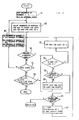
- FIG. 1 is a flowchart of the process for generating recurring random number codes with the first absolute encoder.
- the first P-bit code B'1 composed of 0 or 1 is established in step 1.
- the P bits serve as the first P numbers of a sequence of random numbers.
- the initial code B'1 is shifted one bit to the right (or the left) in step 2. If the initial code B'1 is shifted to the left, then the processing is executed as indicated in the parentheses below.
- the MSB (most significant bit)) (or LSB (least significant bit)) of the initial code B'1 after it has been shifted to the right (or the left) is set at 0. This bit serves as the (P+1)th number of a sequence of random numbers.
- a newly generated P-bit code B'2 and the initial code B'1 are compared with each other in step 3.
- Step 4 determines whether the new code is an Nth code or not. If the new code is an Nth code, control goes to step 6, and if the new code is not an Nth code, control returns to step 2. It is now assumed that at an ith code B' i is generated, and control goes from step 4 back to step 2. In step 2, this code is shifted one bit to the right (or the left), and the MSB (or the LSB) is set at 0, producing a new code B' i+1 . Step 3 then determines whether any of the previous codes B'1 through B' i is the same as code B' i+1 . If not, control goes to step 4.
- step 5 changes the MSB (or the LSB) from 0 to 1, and control goes back to step 3. If the new code B' i+1 is the same as any of the previous codes B'1 through B' i in step 3, control goes again to step 5. At this time, the MSB (or the LSB) is already 1. The code is shifted to the left (or the right) until the MSB (or the LSB) of the sequence of random numbers becomes 0.
- the code is shifted up to a code B'p whose MSB (or LSB) is 0, and the code produced by setting the MSB (or the LSB) of the code B' p to 1 is established as a new code B' p , after which control goes to step 3.
- the above process is repeated.
- step 6 determines whether the code produced by shifting code B' N ' one bit to the right (or the left) is equal to the initial code B'1 or not. If equal, then the process is finished, and if not equal, then control goes to step 5. In this manner, recurring random number codes are produced.
- a second absolute encoder comprises a code plate divided into N equal slits each coded 0 or 1 for producing a sequence of recurring random numbers whose P-bit binary codes (B1 - B N ) composed of P slits, which are M slits apart, are different from each other and a detector device for reading the codes of successive P slits, which are M slits apart, of the code plate so that the absolute angle of the code disc within one revolution can be detected.
- FIG. 2 is a flowchart of the process for generating recurring random number codes with the second absolute encoder.
- the process shown in FIG. 2 generates a sequence of random numbers having a length N, which are M apart.
- Sequences of P-bit numbers 1, 2, ..., M+1 each composed of 0 or 1 with N represented by a binary number are initially established in step 11. These binary codes are referred to as B'1, B'2, ..., B' M+1 , respectively.
- a sequence of numbers having a length (M+1)P in which the bits of the sequences of numbers 1, 2, ..., M+1 are arranged in the order of these sequences of numbers 1, 2, ..., M+1, is referred to as an initial sequence of random numbers.
- the sequence of numbers 1 is shifted one bit to the right (or the left) in step 12. If it is shifted to the left, the processing is executed as indicated in the parentheses below.
- the MSB (or the LSB) of the code after it has been shifted to the right (or the left) is set at 0.
- the newly generated P-bit code B' M+2 is compared with previous codes B'1, B'2, ..., B' M+1 in order to determine whether code B' M+2 is equal to any of the previous codes in step 13. If the compared codes differ from each other, then control goes to step 14, and if the compared codes are equal, control goes to step 16.
- the MSB (or the LSB) of the sequence of numbers 1 is placed on the lefthand side (or the righthand side) of the MSB (or the LSB) of the sequence of random numbers, thus producing a sequence of (M+1)P+1-bit random numbers.
- Step 14 also determines whether the new code is an Nth code or not. If the new code is an Nth code, control goes to step 20, and if the new code is not an Nth code, control returns to step 15. In step 15, the sequence of numbers 2 is replaced with a new sequence of numbers 1, ..., the sequence of numbers M+1 with a new sequence of numbers M, and the sequence of numbers 1 with a new sequence of numbers M+1. Then, step 12 is carried out for the new sequence of numbers 1 to produce a new code B' M+3 . Step 16 determines whether the MSB (or the LSB) of the sequence of numbers 1 to 0 or not. If it is 0, control goes to step 17, and if not, control goes to step 18.
- step 17 the MSB (or the LSB) is changed to 1, and control then goes to step 13.
- Step 18 determines whether the present code is equal to any one of the initial codes B'1, B'2, ..., B' M+1 or not. If equal, control goes to step 21, and if not equal, control goes to step 19.
- step 19 each of the sequences of numbers 1, 2, ..., M+1 is shifted one bit to the left (or the right), and control then goes back to step 16. At this time, the sequence of random numbers is shifted back by M+1 bits.
- the sequence of numbers 1 is shifted to the left (or the right) until the MSB (or the LSB) of the sequence of numbers 1 becomes 0 or the sequence of numbers 1 becomes an initial code.
- Step 21 determines whether the present code is of the maximum value which can be taken by a P-bit binary number. If not the maximum value, control goes to step 22, and if it is the maximum value, the process is finished since no sequence of random numbers can be produced by the algorithm shown in FIG. 2. In step 22, the code produced by incrementing the present code by 1 is referred to as the new initial code, and control then goes to step 13.
- step 12 the new sequence of numbers 1 is shifted one bit to the right (or the left), and the MSB (or the LSB) is set at 0, producing a new code B' i+1 .
- step 13 determines whether the code B' i+1 is equal to any of the codes B'1, ..., B' i or not. If not equal, then control goes to step 14. If equal, the MSB (or the LSB) is then changed from 0 to 1 in steps 16 and 17, and thereafter control goes to step 13. if the new code B' i+1 is equal to any of the codes B'1, ..., B' i in step 13, control returns to step 16.
- the code Since the MSB (or the LSB) is already 1 at this time, the code is shifted to the left (or the right) until the MSB (or the LSB) of the sequence of numbers 1 becomes 0. That is, the code is shifted up to a code B' j whose MSB (or LSB) bit is 0.
- a code produced by changing the MSB (or the LSB) bit of the code B' j to 1 is set as a new code B' j , after which control goes to step 13. The above process is repeated.
- step 20 determines whether codes B' N+1 , ..., B' N+M+1 produced by shifting the codes B' N-M , ..., B' N (i.e., the sequences of numbers 2, ..., M+1, 1) one bit to the right (or the left) and setting the MSB (or the LSB) bit to 0 or 1 is equal to the initial codes B'1, ..., B' M+1 or not. If equal, the process is finished, and if not equal, control then goes to step 16. In this manner, a sequence of recurring random number codes having a length N, which are M bits apart, is produced.
- an absolute encoder having a desired resolution.
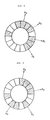
- FIG. 3 shows the code plate of the absolute encoder according to the first embodiment of the present invention.
- Table 3 shows the process of generating the sequence of recurring random numbers shown in Table 2, using the algorithm shown in FIG. 1.
- the random number code produced each time control reaches step 3 shown in FIG. 1 is shown in Table 3.
- step 6 determines whether the No. 37 code "0000" is the same as the initial code or not. Since the No. 37 code is the same as the initial code, the desired sequence of random numbers is obtained.
- the sequence of random numbers thus produced may be of any desired length N. Therefore, it is posssible to produce an absolute encoder having a resolution N, the encoder including a code plate having slits corresponding to the sequence of random numbers. Another encoder having resolution N with incremental slits may also be produced instead of the encoder with a random number of slits. It is also possible to provide a multi-rotation-type absolute encoder having means on one code plate or one rotational central shaft for producing incremental pulses, one for each revolution, and a means for counting the produced pulses with a counter.
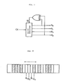
- FIG. 4 is a block diagram of the random code generator for generating the 4-bit random number codes shown in Table 2.
- the random code generator comprises a shift register 31, an exclusive-OR gate 32, a NOR gate 33, inverters 34, 35, AND gates 36, 37, and an OR gate 38.
- the random code generator includes an additional circuit arrangement for adding 0 to a pattern transition 1000 ⁇ 0001 produced by the circuit shown in FIG. 7, so that pattern transitions 1000 ⁇ 0000 ⁇ 0001 can be achieved. More specifically, when all three of the bits R0 through R3 are 0, the next shift input is determined according to the value of R3. Otherwise, the random code generator shown in FIG. 4 produces the same patterns as those of the circuit shown in FIG. 7.
- FIG. 5 shows the code plate of an absolute encoder according to the second embodiment of the present invention.
- Table 5 shows the process for generating the sequence of recurring random numbers shown in Table 4 using the algorithm shown in FIG. 2.
- a random number code produced each time control reaches step 13 shown in FIG. 2 is shown in Table 5.
- the sixteenth code B'16 is produced at No. 120. Since the No. 121 and No. 122 are the same as the initial codes B'1, B'2, the desired sequence of random numbers is obtained.
- FIG. 6 shows the code plate of an absolute encoder according to the third embodiment of the present invention.
- Table 7 shows the process for generating the sequence of recurring random numbers shown in Table 6 using the algorithm shown in FIG. 2.
- the random number code produced each time control reaches step 13 shown in FIG. 2 is shown in Table 7.
- step 12 "1000" is set as the sequence of numbers 1, B'1 at No. 1, "1001” as the sequence of numbers 2, B'2 at No. 2, and "0000" as the sequence of numbers 3, B'3 at No. 3.
- the sequence of numbers 1 is shifted to the right in step 12, producing the No. 4 code B'4. Since no previous code is equal to the No. 4 code B'4 in step 13, control goes to step 14.
- N is not 16
- control goes to step 15 in which the sequence of numbers 2 is replaced with the new sequence of numbers 1, the sequence of numbers 3 with the new sequence of numbers 2, and the sequence of numbers 1 with the new sequence of numbers 3, after which control goes to step 12 again.
- the new sequence of numbers 1 is shifted to the right, producing the No. 5 code B'5. Because the No.
- the sixteenth code B'16 is produced at No. 848. Since the No. 848, No. 849 and No. 850 are the same as the initial codes B'1, B'2, B'3 (not shown), the desired sequence of random numbers is obtained.
- the present invention has been described with reference to the rotary-type slit code plate.
- the present invention is also applicable to a linear-type code plate.
- a linear-type code plate is employed, as shown in FIG. 8, an absolute position can be determined within the range of N-P slits.
- the above description is directed to an optical encoder. If the present invention is incorporated in a magnetic encoder, bits 1 and 0 may be represented by magnetic pole patterns of N and S poles.
Landscapes
- Physics & Mathematics (AREA)
- General Physics & Mathematics (AREA)
- Engineering & Computer Science (AREA)
- Theoretical Computer Science (AREA)
- Transmission And Conversion Of Sensor Element Output (AREA)
- Analogue/Digital Conversion (AREA)
Applications Claiming Priority (2)
| Application Number | Priority Date | Filing Date | Title |
|---|---|---|---|
| JP1174121A JP2785349B2 (ja) | 1988-07-25 | 1989-07-07 | 絶対値エンコーダの符号パターン作成方法 |
| JP174121/89 | 1989-07-07 |
Publications (2)
| Publication Number | Publication Date |
|---|---|
| EP0441963A1 true EP0441963A1 (de) | 1991-08-21 |
| EP0441963A4 EP0441963A4 (en) | 1991-11-21 |
Family
ID=15973014
Family Applications (1)
| Application Number | Title | Priority Date | Filing Date |
|---|---|---|---|
| EP19900901883 Withdrawn EP0441963A4 (en) | 1989-07-07 | 1990-01-23 | Absolute value encoder |
Country Status (4)
| Country | Link |
|---|---|
| US (1) | US5117105A (de) |
| EP (1) | EP0441963A4 (de) |
| KR (1) | KR950010385B1 (de) |
| WO (1) | WO1991000984A1 (de) |
Cited By (5)
| Publication number | Priority date | Publication date | Assignee | Title |
|---|---|---|---|---|
| DE4224654A1 (de) * | 1992-07-25 | 1994-01-27 | Bosch Gmbh Robert | Positionsmeßeinrichtung |
| DE4338038C1 (de) * | 1993-11-08 | 1995-03-16 | Zeiss Carl Jena Gmbh | Verfahren zur Kodierung eines maschinell lesbaren Meßstabes |
| EP0881469A1 (de) * | 1997-05-30 | 1998-12-02 | Hewlett-Packard Company | Kodierer für absolute Position mit inkrementalen und absoluten Spuren |
| GB2357836A (en) * | 1999-09-11 | 2001-07-04 | Huntleigh Technology Plc | Position sensor |
| US6714540B1 (en) * | 1998-02-25 | 2004-03-30 | Matsushita Electric Industrial Co., Ltd. | Data communication method, communication frame generating method, and medium on which program for carrying out the methods are recorded |
Families Citing this family (12)
| Publication number | Priority date | Publication date | Assignee | Title |
|---|---|---|---|---|
| US5220161A (en) * | 1992-03-23 | 1993-06-15 | Miles Inc. | Position-sensing and motion verification assembly for a motor-driven mechanism |
| US5418362A (en) * | 1993-05-27 | 1995-05-23 | Lusby; Brett L. | Encoder for determining absolute linear and rotational positions |
| US5880683A (en) * | 1993-07-22 | 1999-03-09 | Bourns, Inc. | Absolute digital position encoder |
| US5739775A (en) * | 1993-07-22 | 1998-04-14 | Bourns, Inc. | Digital input and control device |
| GB2319079B (en) * | 1996-10-29 | 2000-07-12 | Baxter Int | Infusion pump monitoring encoder/decoder |
| US5841274A (en) * | 1997-01-29 | 1998-11-24 | Mitutoyo Corporation | Induced current absolute position transducer using a code-track-type scale and read head |
| US6568777B1 (en) * | 1999-11-16 | 2003-05-27 | Agilent Technologies, Inc. | Optical navigation system and method |
| JP2001208503A (ja) * | 2000-01-25 | 2001-08-03 | Harmonic Drive Syst Ind Co Ltd | リニアアクチュエータの絶対位置検出装置 |
| JP2004163302A (ja) * | 2002-11-14 | 2004-06-10 | Harmonic Drive Syst Ind Co Ltd | 光学式エンコーダ |
| US7191943B2 (en) * | 2004-07-28 | 2007-03-20 | Caterpillar Inc | Robust barcode and reader for rod position determination |
| US7289041B2 (en) * | 2006-03-14 | 2007-10-30 | Control Devices, Inc. | Absolute position chain encoder |
| CN115993140A (zh) * | 2022-12-14 | 2023-04-21 | 广州南方卫星导航仪器有限公司 | 绝对值编码器的刻线方法、存储介质、设备及编码器 |
Family Cites Families (6)
| Publication number | Priority date | Publication date | Assignee | Title |
|---|---|---|---|---|
| JPS5099564A (de) * | 1973-12-28 | 1975-08-07 | ||
| JPS5319852A (en) * | 1976-08-07 | 1978-02-23 | Anritsu Electric Co Ltd | Shaft angle encoder |
| JPS5439653A (en) * | 1977-09-05 | 1979-03-27 | Ricoh Co Ltd | Coding system |
| US4720699A (en) * | 1985-10-28 | 1988-01-19 | Smith Ronald H | Optical encoder using line array detectors |
| GB2183951B (en) * | 1985-11-28 | 1990-05-23 | Duracell Int | Displacement measuring apparatus |
| US5038243A (en) * | 1989-07-19 | 1991-08-06 | Hewlett-Packard Company | Local initialization for incremental encoder |
-
1990
- 1990-01-23 WO PCT/JP1990/000072 patent/WO1991000984A1/ja not_active Ceased
- 1990-01-23 US US07/651,387 patent/US5117105A/en not_active Expired - Lifetime
- 1990-01-23 EP EP19900901883 patent/EP0441963A4/en not_active Withdrawn
- 1990-07-07 KR KR1019910700256A patent/KR950010385B1/ko not_active Expired - Fee Related
Cited By (6)
| Publication number | Priority date | Publication date | Assignee | Title |
|---|---|---|---|---|
| DE4224654A1 (de) * | 1992-07-25 | 1994-01-27 | Bosch Gmbh Robert | Positionsmeßeinrichtung |
| DE4338038C1 (de) * | 1993-11-08 | 1995-03-16 | Zeiss Carl Jena Gmbh | Verfahren zur Kodierung eines maschinell lesbaren Meßstabes |
| US5572009A (en) * | 1993-11-08 | 1996-11-05 | Carl Zeiss Jena Gmbh | Method for encoding a machine-readable measurement scale |
| EP0881469A1 (de) * | 1997-05-30 | 1998-12-02 | Hewlett-Packard Company | Kodierer für absolute Position mit inkrementalen und absoluten Spuren |
| US6714540B1 (en) * | 1998-02-25 | 2004-03-30 | Matsushita Electric Industrial Co., Ltd. | Data communication method, communication frame generating method, and medium on which program for carrying out the methods are recorded |
| GB2357836A (en) * | 1999-09-11 | 2001-07-04 | Huntleigh Technology Plc | Position sensor |
Also Published As
| Publication number | Publication date |
|---|---|
| KR950010385B1 (ko) | 1995-09-16 |
| US5117105A (en) | 1992-05-26 |
| WO1991000984A1 (fr) | 1991-01-24 |
| EP0441963A4 (en) | 1991-11-21 |
| KR920701786A (ko) | 1992-08-12 |
Similar Documents
| Publication | Publication Date | Title |
|---|---|---|
| US5117105A (en) | Absolute encoder | |
| CA1075817A (en) | Sequential encoding and decoding of variable word length fixed rate data codes | |
| JP2754422B2 (ja) | アブソリュート・エンコーダ | |
| EP0332244A1 (de) | Absolutkodierer mit einer einzigen Spur | |
| JP3179493B2 (ja) | アブソリュートエンコーダ | |
| US4947166A (en) | Single track absolute encoder | |
| EP0414953B1 (de) | Positionswertgeber | |
| US4901072A (en) | Position detector utilizing gray code format | |
| JP2785349B2 (ja) | 絶対値エンコーダの符号パターン作成方法 | |
| US5774068A (en) | Absolute signal detecting method and absolute encoder | |
| US5565864A (en) | Absolute encoder | |
| JP3171485B2 (ja) | 高分解能アブソリュート信号の作成方法 | |
| JP3111546B2 (ja) | アブソリュートエンコーダ | |
| GB2180083A (en) | Non-volatile electronic counters | |
| JP4279630B2 (ja) | アブソリュートエンコーダ | |
| JP3449794B2 (ja) | 絶対値エンコーダ | |
| JPS6129176B2 (de) | ||
| JP3449775B2 (ja) | 絶対値エンコーダ | |
| JP3303472B2 (ja) | アブソリュートエンコーダ | |
| US11204265B2 (en) | Rotary coding disc and method for designing the same | |
| JP3053710B2 (ja) | 絶対位置検出装置 | |
| JP3454907B2 (ja) | 絶対値エンコーダ | |
| JP3490759B2 (ja) | アブソリュートエンコーダ | |
| JPH0259612A (ja) | アブソリュートエンコーダ | |
| JPH0374328B2 (de) |
Legal Events
| Date | Code | Title | Description |
|---|---|---|---|
| PUAI | Public reference made under article 153(3) epc to a published international application that has entered the european phase |
Free format text: ORIGINAL CODE: 0009012 |
|
| AK | Designated contracting states |
Kind code of ref document: A1 Designated state(s): CH DE ES FR GB IT LI SE |
|
| 17P | Request for examination filed |
Effective date: 19910711 |
|
| A4 | Supplementary search report drawn up and despatched |
Effective date: 19911003 |
|
| AK | Designated contracting states |
Kind code of ref document: A4 Designated state(s): CH DE ES FR GB IT LI SE |
|
| 17Q | First examination report despatched |
Effective date: 19940216 |
|
| STAA | Information on the status of an ep patent application or granted ep patent |
Free format text: STATUS: THE APPLICATION IS DEEMED TO BE WITHDRAWN |
|
| 18D | Application deemed to be withdrawn |
Effective date: 19940827 |