EP0441172A2 - Rammvorrichtung - Google Patents
Rammvorrichtung Download PDFInfo
- Publication number
- EP0441172A2 EP0441172A2 EP91100788A EP91100788A EP0441172A2 EP 0441172 A2 EP0441172 A2 EP 0441172A2 EP 91100788 A EP91100788 A EP 91100788A EP 91100788 A EP91100788 A EP 91100788A EP 0441172 A2 EP0441172 A2 EP 0441172A2
- Authority
- EP
- European Patent Office
- Prior art keywords
- control
- piston
- end piece
- percussion piston
- compressed air
- Prior art date
- Legal status (The legal status is an assumption and is not a legal conclusion. Google has not performed a legal analysis and makes no representation as to the accuracy of the status listed.)
- Granted
Links
Images

Classifications
-
- E—FIXED CONSTRUCTIONS
- E21—EARTH OR ROCK DRILLING; MINING
- E21B—EARTH OR ROCK DRILLING; OBTAINING OIL, GAS, WATER, SOLUBLE OR MELTABLE MATERIALS OR A SLURRY OF MINERALS FROM WELLS
- E21B4/00—Drives for drilling, used in the borehole
- E21B4/06—Down-hole impacting means, e.g. hammers
- E21B4/14—Fluid operated hammers
- E21B4/145—Fluid operated hammers of the self propelled-type, e.g. with a reverse mode to retract the device from the hole
Definitions
- the invention relates to a ramming device with a pneumatically driven percussion piston movable reciprocally in an axial direction in a housing and a control device which has a control part which is movable with the percussion piston and a control part which cooperates with the latter and is held on the housing and controls the pressurization of the percussion piston.
- Such ramming devices are used, for example, to advance earth bores for cables and lines laid underground.
- control device is usually formed by a tubular extension extending from the rear end of the percussion piston and a control sleeve which engages into the interior of the extension and which is supported on an axially extending support part on a rear end piece of the housing.
- the control sleeve and the percussion piston with the tubular extension form a rear pressure chamber which is supplied with compressed air via a supply channel formed in the support part for the control sleeve and which causes the percussion piston to move forward.
- a reversal of the drive direction can be achieved in the known device in that the control sleeve by means of a to the device connected compressed air hose is adjusted so that the front pressure chamber is pressurized earlier. The forward movement of the percussion piston is then cushioned, and at the end of the backward movement the percussion piston strikes the end piece so that an inward-directed pulse is transmitted to the housing.
- the control sleeve is adjusted in the axial direction with the aid of a spindle drive by rotating the compressed air hose.
- control sleeve is adjusted in the axial direction when the device is switched off by pulling or pushing the compressed air hose, or in which the control sleeve is provided with recesses which, by rotating the control sleeve with the aid of the compressed air hose, into one of the radial channels of the tubular Forzatzes corresponding position can be used (DE-PS 31 04 547).
- the main section of the percussion piston must have a certain length so that a sufficient inert mass of the percussion piston is achieved.
- the length of the control section is determined by the stroke of the percussion piston and, if necessary, by the axial displacement of the control sleeve.
- the end piece of the housing serves to fasten the supporting part and the control sleeve and must also withstand the impact of the percussion piston when driving the device in the backward direction, but is on the other hand weakened by the axial ventilation channels. This end piece must therefore also have a certain length for reasons of stability. For these reasons, the conventional devices have a relatively large overall length.
- the invention has for its object to provide a ramming device which has a smaller overall length for a given mass of the percussion piston.
- the housing-side control part is formed by the end piece of the housing, and that with the percussion piston movable control part is formed by a control piston projecting axially from the percussion piston, which plunges into an opening of the end piece.
- the end piece is thus included in the control direction, so that, compared to the prior art, the overall length of the percussion piston remains unchanged, and a reduction in the overall length is achieved, or a greater mass of the percussion piston is made possible with the overall length unchanged.
- the rear pressure chamber formed between the main part of the percussion piston and the end piece is directly connected to the pressure source, and the pressure supply and ventilation of the front pressure chamber is controlled by control channels arranged radially in the control piston, which are connected to the front pressure chamber via an axial channel of the percussion piston are and are open to the rear pressure chamber in the front end position of the percussion piston.
- a particularly simple and space-saving design is achieved in that the end piece is provided with a through opening and the control piston projects so far rearward from the end piece in the rear end position of the percussion piston that the control channels are open to the atmosphere.
- the end piece is provided with a branch line, via which the control channels of the control piston can already be connected to the pressure source within the end piece. Compressed air can already be introduced into the front pressure chamber via this branch line before the percussion piston reaches its front end position. This dampens the forward movement of the percussion piston. If the control channels of the control piston pass through the end piece during the subsequent backward movement of the percussion piston, the front pressure chamber receives an additional pressure surge via the branch line, so that the backward stroke of the piston is extended.
- the compressed air supply to the rear pressure chamber preferably takes place via an axial bore formed in the end piece, which defines the end of the compressed air hose receives and from which the branch line branches off in such a way that the mouth of the branch line can be opened and closed by moving or rotating the compressed air hose.
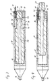
- a ramming device shown in FIGS. 1 and 2 has a housing 12 provided with a striking tip 10, which is closed at the rear end by an end piece 14.
- a front pressure chamber 18 and a rear pressure chamber 20 are formed in the interior of the housing 12 by an impact piston 16 which is axially movably guided in the housing.
- the percussion piston 16 is provided at the rear end with an axially projecting control piston 22, which plunges into an opening 24 of the end piece 14 and is slidably guided in this opening.
- the control piston has radial control channels 26 which are connected to the front pressure chamber 18 via an axial channel 28.
- a compressed air hose 30 is connected to the rear pressure chamber 20.
- the front pressure chamber 18 When the percussion piston 16 is in the front end position shown in FIG. 1, the front pressure chamber 18 is supplied with compressed air via the compressed air hose 30, the rear pressure chamber 20, the radial control channels 26 and the axial channel 28.
- the pressure in the front pressure chamber 18 acts on the entire cross-sectional area of the percussion piston 16, while the pressure prevailing in the rear chamber 20 acts only on the annular surface outside the control piston 22.
- the percussion piston 16 is therefore moved in the reverse direction.
- the control channels 26 enter the end piece 14 the compressed air supply for the front pressure chamber 18 is interrupted. Due to the inertia, the percussion piston 16 continues to move back until it reaches the position shown in FIG. 2.
- control channels 26 are connected to the atmosphere outside the end piece 14, so that the front pressure chamber 18 is vented. Due to the pressure still prevailing in the rear pressure chamber 20, the percussion piston 16 is braked and driven in the forward direction. In the course of the forward movement, the percussion piston 16 is accelerated further, so that it strikes the front end of the housing 12 at high speed and transmits a propulsion impulse to the housing.
- FIGS. 1 and 2 The ramming device shown in FIGS. 1 and 2 is preferably used only as a striking device outside of the ground because of the laterally connected compressed air hose 30.
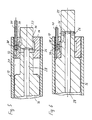
- FIGS. 3 to 6 show a ramming device which is suitable for use in the ground, since the compressed air hose 30 enters the housing axially from the rear. This device also offers the possibility of reversing the direction of advance by remote control.
- the device according to FIGS. 3 to 6 differs from the previously described exemplary embodiment in the following features.
- the compressed air hose 30 is rotatably held in an axial bore 32 of the end piece 14.
- the axial bore 32 is connected via a radial bore 34 to an annular chamber 36 which surrounds the circumference of the control piston 22.
- the compressed air hose 30 is provided with a lateral opening 38 which is in the same axial position as the radial bore 34. In the position shown in Figures 3, 4 and 5, however, the lateral opening 38 of the compressed air hose is turned away from the radial bore 34, so that the compressed air only enters the rear pressure chamber 20. In this position, the ramming device is driven in the forward direction, as described above in connection with Figures 1 and 2.
- the lateral opening 38 of the compressed air hose is aligned with the radial bore 34 of the end piece, and the opening 38, the radial bore 34 and the annular chamber 36 form a branch line, via which the front Pressure chamber 18 can be supplied with compressed air while the control channels 26 pass the end piece.
- the front pressure chamber 18 is again supplied with compressed air as soon as the control channels 26 enter the annular chamber 36 again.
- the forward movement of the percussion piston is thereby braked and finally reversed, so that the percussion piston does not strike the front end of the housing 12.
- the length of the annular chamber 36 in the axial direction is selected so that braking and reversal of the movement of the percussion piston 16 can be achieved over this length. However, even if the percussion piston should shoot beyond the intended reverse position so that the control channels 26 are separated from the annular chamber 36, there is no malfunction. since in this case the air volume of the front pressure chamber 18 is compressed so that the percussion piston springs back elastically.
- the direction of advance can be reversed in a simple manner due to the mode of operation described above, by rotating the compressed air hose 30 about its longitudinal axis.
- the reversal can also be effected in that the compressed air hose 30 is displaced in the axial direction or at the same time displaced and rotated.
- a pull-out protection prevents the compressed air hose 30 from being pulled out of the end piece 14 entirely.
- the reversal can also be effected via a valve arranged in the end piece 14, which is actuated by a cable or other remote control means or which switches over automatically when the pressure supply is switched off.
- the end piece 14 is arranged directly at the end of the housing shell, so that the control piston 22 projects freely out of the housing in its rear end position.
- the housing 12 can, however, also be extended beyond the end piece 14 to the rear, or further housing parts can be connected to the end piece at the rear.
- a component with a sieve or a protective device it is possible to attach a component with a sieve or a protective device to prevent dirt from entering the machine body.
- the term “end piece” in the sense of the present application is to be understood as a component which is located at the end of one of the pressure chambers, but not necessarily at the end of the housing.
Landscapes
- Engineering & Computer Science (AREA)
- Geology (AREA)
- Mining & Mineral Resources (AREA)
- Life Sciences & Earth Sciences (AREA)
- General Life Sciences & Earth Sciences (AREA)
- Fluid Mechanics (AREA)
- Environmental & Geological Engineering (AREA)
- Physics & Mathematics (AREA)
- Mechanical Engineering (AREA)
- Geochemistry & Mineralogy (AREA)
- Earth Drilling (AREA)
- Surgical Instruments (AREA)
- Stored Programmes (AREA)
- Press Drives And Press Lines (AREA)
- Catching Or Destruction (AREA)
- Devices For Checking Fares Or Tickets At Control Points (AREA)
- Percussive Tools And Related Accessories (AREA)
Abstract
Description
- Die Erfindung betrifft eine Rammvorrichtung mit einem in Axialrichtung hin- und hergehend in einem Gehäuse beweglichen, pneumatisch angetriebenen Schlagkolben und einer Steuereinrichtung, die ein mit dem Schlagkolben bewegliches Steuerteil und ein mit diesem zusammenwirkendes, am Gehäuse gehaltenes Steuerteil aufweist und die Druckbeaufschlagung des Schlagkolbens steuert.
- Derartige Rammvorrichtungen dienen beispielsweise zum Vortreiben von Erdbohrungen für unterirdisch verlegte Kabel und Leitungen.
- Ein Beispiel einer herkömmlichen Rammvorrichtung dieser Gattung wird in dem DE-GM 87 00 076 beschrieben. Die Steuereinrichtung wird bei herkömmlichen Rammvorrichtungen üblicherweise durch einen vom rückwärtigen Ende des Schlagkolbens ausgehenden rohrförmigen Fortsatz und eine in das Innere des Fortsatzes eingreifende Steuerhülse gebildet, die sich über ein axial verlaufendes Tragteil an einem rückwärtigen Endstück des Gehäuses abstützt. Die Steuerhülse und der Schlagkolben mit dem rohrförmigen Fortsatz bilden eine rückwärtige Druckkammer, die über einen in dem Tragteil für die Steuerhülse ausgebildeten Zufuhrkanal mit Druckluft versorgt wird und die Vorwärtsbewegung des Schlagkolbens bewirkt. Wenn der Schlagkolben seine vordere Endstellung erreicht und die Schlagenergie auf das Gehäuse überträgt, werden radiale Kanäle des rohrförmigen Fortsatzes des Schlagkolbens durch den vorderen Rand der Steuerhülse freigegeben, so daß die Druckluft durch diese radialen Kanäle und durch in dem Schlagkolben ausgebildete Axialkanäle in eine vordere Druckkammer strömt. Hierdurch wird die Rückwärtsbewegung des Schlagkolbens eingeleitet, da der Schlagkolben gegenüber der vorderen Druckkammer eine größere Wirkfläche aufweist als gegenüber der rückwärtigen Druckkammer. Bei der Rückwärtsbewegung des Schlagkolbens werden die radialen Kanäle des rohrförigen Fortsatzes vorübergehend durch die Steuerhülse blockiert. Wenn die radialen Kanäle den hinteren Rand der Steuerhülse erreichen, kann sich der Druck in der vorderen Druckkammer über diese Kanäle und über in dem Endstück des Gehäuses ausgebildete Lüftungskanäle entspannen, so daß ein neuer Schlagkzyklus beginnt.
- Eine Umkehr der Antriebsrichtung läßt sich bei der bekannten Vorrichtung dadurch erreichen, daß die Steuerhülse mit Hilfe eines an die Vorrichtung angeschlossenen Druckluftschlauches so verstellt wird, daß die vordere Druckkammer früher mit Druckluft beaufschlagt wird. Die Vorwärtsbewegung des Schlagkolbens wird dann welch abgefedert, und am Ende der Rückwärtsbewegung trifft der Schlagkolben auf das Endstück auf, so daß einrückwärts gerichteter Impuls auf das Gehäuse übertragen wird. Gemäß dem DE-GM 87 00 076 wird die Steuerhülse mit Hilfe eines Spindelantriebs in Axialrichtung verstellt, indem der Druckluftschlauch gedreht wird. Es sind jedoch auch Vorrichtungen gekannt, bei denen die Steuerhülse bei abgeschaltetem Gerät durch Ziehen oder Schieben des Druckluftschlauches in Axialrichtung verstellt wird oder bei denen die Steuerhülse mit Ausnehmungen versehen ist, die durch Drehen der Steuerhülse mit Hilfe des Druckluftschlauches in eine den radialen Kanälen des rohrförmigen Forzsatzes entsprechende Position gebraucht werden können (DE-PS 31 04 547).
- Bei den bekannten Vorrichtungen lassen sich in Längsrichtung drei hintereinander liegende Abschnitte unterscheiden: der Hauptabschnitt des Schlagkolbens, ein durch den rohrförmgen Fortsatz des Schlagkolbens, die Steuerhülse und das Tragteil gebildeter Steuerabschnitt und schließlich das Endstück des Gehäuses. Der Hauptabschnitt des Schlagkolbens muß eine gewisse Länge aufweisen, damit eine hinreichende träge Masse des Schlagkolbens erreicht wird. Die Länge des Steuerabschnittes wird durch den Hubweg des Schlagkolbens und ggf. durch den axialen Verstellweg der Steuerhülse bestimmt. Das Endstück des Gehäuses dient zur Befestigung des Tragteils und der Steuerhülse und muß außerdem beim Antrieb der Vorrichtung in Rückwärtsrichtung dem Aufprall des Schlagkolbens standhalten, ist jedoch andererseits durch die axialen Lüftungskanäle geschwächt. Dieses Endstück muß deshalb aus Stabilitätsgründen ebenfalls eine gewisse Länge aufweisen. Aus diesen Gründen weisen die herkömmlichen Vorrichtungen eine relativ große Gesamtlänge auf.
- Der Erfindung liegt die Aufgabe zugrunde, eine Rammvorrichtung zu schaffen, die bei gegebener Masse des Schlagkolbens eine geringere Gesamtlänge aufweist.
- Diese Aufgabe wird erfindungsgemäß gelöst durch eine Rammvorrichtung mit den in Anspruch 1 angegebenen Merkmalen.
- Bei der vorgeschlagenen Rammvorrichtung wird das gehäuseseitige Steuerteil durch das Endstück des Gehäuses gebildet, und das mit dem Schlagkolben bewegliche Steuerteil wird durch einen axial von dem Schlagkolben vorspringenden Steuerkolben gebildet, der in eine Öffnung des Endstückes eintaucht. Bei dieser Konstruktion ist somit das Endstück in die Steuerrichtung einbezogen, so daß gegenüber dem Stand der Technik bei unveränderter Masse des Schlagkolbens eine Verringerung der Gesamtlänge erreicht wird bzw. bei unveränderter Gesamtlänge eine größere Masse des Schlagkolbens ermöglicht wird.
- Vorteilhafte Ausgestaltungen und Weiterbildungen der Erfindung ergeben sich aus den Unteransprüchen.
- Bevorzugt ist die zwischen dem Hauptteil des Schlagkolbens und dem Endstück gebildete hintere Druckkammer direkt mit der Druckquelle verbunden, und die Druckzufuhr und Entlüftung der vorderen Druckkammer wird durch radial in dem Steuerkolben angeordnete Steuerkanäle gesteuert, die über einen axialen Kanal des Schlagkolbens mit der vorderen Druckkammer verbunden sind und in der vorderen Endstellung des Schlagkolbens zur hinteren Druckkammer geöffnet sind.
- Eine besonders einfache und raumsparende Konstruktion wird dadurch erreicht, daß das Endstück mit einer durchgehenden Öffnung versehen ist und der Steuerkolben in der rückwärtigen Endstellung des Schlagkolbens so weit nach hinten aus dem Endstück herausragt, daß die Steuerkanäle zur Atmosphäre hin offen sind.
- Um eine Umkehr der Antriebsrichtung zu ermöglichen, ist bei der erfindungsgemäßen Vorrichtung das Endstück mit einer Zweigleitung versehen, über die die Steuerkanäle des Steuerkolbens bereits innerhalb des Endstückes mit der Druckquelle verbindbar sind. Über diese Zweigleitung kann bereits Druckluft in die vordere Druckkammer eingeleitet werden, bevor der Schlagkolben seine vordere Endstellung erreicht. Auf diese Weise wird die Vorwärtsbewegung des Schlagkolbens gedämpft. Wenn die Steuerkanäle des Steuerkolbens bei der anschließenden Rückwärtsbewegung des Schlagkolbens das Endstück durchlaufen, erhält die vordere Druckkammer über die Zweigleitung einen zusätzlichen Druckstoß, so daß der Rückwärtshub des Kolbens verlängert wird.
- Die Druckluftzufuhr zu der hinteren Druckkammer erfolgt vorzugsweise über eine in dem Endstück gebildete Axialbohrung, die das Ende des Druckluftschlauches aufnimmt und von der die Zweigleitung derart abzweigt, daß die Mündung der Zweigleitung durch Verschieben oder Drehen des Druckluftschlauches geöffnet und verschlossen werden kann.
- Im folgenden werden bevorzugte Ausführungsbeispiele der Erfindung anhand der Zeichnungen näher erläutert.
- Es zeigen:
- Fig. 1
- einen Längsschnitt durch eine Rammvorrichtung mit in der vorderen Endstellung befindlichem Schlagkolben;
- Fig. 2
- einen Längsschnitt durch die Rammvorrichtung mit in rückwärtiger Stellung befindlichen Schlagkolben;
- Fig. 3 und 4
- Längsschnitte durch ein abgewandeltes Ausführungsbeispiel der Rammvorrichtung mit in der vorderen bzw. rückwärtigen Stellung befindlichem Schlagkolben;
- Fig. 5
- einen vergrößerten Schnitt durch eine Steuereinrichtung der Rammvorrichtung gemäß Figuren 3 und 4 in einer Steuerposition für den Antrieb in Vorwärtsrichtung; und
- Fig. 6
- einen Schnitt durch die Steuereinrichtung gemäß Figur 5 in einer Steuerposition für den Antrieb in Rückwärtsrichtung.
- Eine in Figuren 1 und 2 gezeigte Rammvorrichtung weist ein mit einer Schlagspitze 10 versehenes Gehäuse 12 auf, das am rückwärtigen Ende durch ein Endstück 14 abgeschlossen ist. Im Inneren des Gehäuses 12 werden durch einen axial beweglich in dem Gehäuse geführten Schlagkolben 16 eine vordere Druckkammer 18 und eine hintere Druckkammer 20 gebildet. Der Schlagkolben 16 ist am rückwärtigen Ende mit einem axial vorspringenden Steuerkolben 22 versehen, der in eine Öffnung 24 des Endstücks 14 eintaucht und gleitend in dieser Öffnung geführt ist. Der Steuerkolben weist radiale Steuerkanäle 26 auf, die über einen axialen Kanal 28 mit der vorderen Druckkammer 18 verbunden sind. Ein Druckluftschlauch 30 ist an die hintere Druckkammer 20 angeschlossen.
- Wenn sich der Schlagkolben 16 in der in Figur 1 gezeigten vorderen Endstellung befindet, so wird die vordere Druckkammer 18 über den Druckluftschlauch 30, die hintere Druckkammer 20, die radialen Steuerkanäle 26 und den axialen Kanal 28 mit Druckluft versorgt. Der Druck in der vorderen Druckkammer 18 wirkt auf die gesamte Querschnittsfläche des Schlagkolbens 16, während der in der hinteren Kammer 20 herrschende Druck lediglich auf die Ringfläche außerhalb des Steuerkolbens 22 wirkt. Der Schlagkolben 16 wird deshalb in Rückwärtsrichtung bewegt. Wenn die Steuerkanäle 26 in das Endstück 14 eintreten, wird die Druckluftversorgung für die vordere Druckkammer 18 unterbrochen. Aufgrund der Massenträgheit bewegt sich der Schlagkolben 16 jedoch weiter zurück, bis er die in Figur 2 gezeigte Stellung erreicht. In dieser Stellung sind die Steuerkanäle 26 außerhalb des Endstückes 14 mit der Atmosphäre verbunden, so daß die vordere Druckkammer 18 entlüftet wird. Durch den weiterhin in der hinteren Druckkammer 20 herrschenden Druck wird der Schlagkolben 16 abgebremst und in Vorwärtsrichtung angetrieben. Im Verlauf der Vorwärtsbewegung wird der Schlagkolben 16 weiter beschleunigt, so daß er mit hoher Geschwindigkeit auf das vordere Ende des Gehäuses 12 aufprallt und einen Vortriebsimpuls auf das Gehäuse überträgt.
- Die oben beschriebenen Vorgänge wiederholen sich periodisch, so daß die Rammvorrichtung im Erdreich vorgetrieben wird.
- Die in Figuren 1 und 2 gezeigte Rammvorrichtung wird wegen des seitlich angeschlossenen Druckluftschlauches 30 vorzugsweise nur als Schlaggerät außerhalb des Erdreichs eingesetzt. Figuren 3 bis 6 zeigen dagegen eine Rammvorrichtung, die für den Einsatz im Erdreich geeignet ist, da der Druckluftschlauch 30 axial von hinten in das Gehäuse eintritt. Bei dieser Vorrichtung besteht außerdem die Möglichkeit, die Vortriebsrichtung ferngesteuert umzukehren. Die Vorrichtung nach Figuren 3 bis 6 unterscheidet sich von dem zuvor beschriebenen Ausführungsbeispiel die folgenden Merkmale.
- Der Druckluftschlauch 30 ist drehbar in einer Axialbohrung 32 des Endstücks 14 gehalten. Die Axialbohrung 32 ist über eine radiale Bohrung 34 mit einer Ringkammer 36 verbunden, die den Umfang des Steuerkolbens 22 umgibt. Der Druckluftschlauch 30 ist mit einer seitlichen Öffnung 38 versehen, die sich in der gleichen axialen Position wie die radiale Bohrung 34 befindet. In der in Figuren 3, 4 und 5 gezeigten Stellung ist die seitliche Öffnung 38 des Druckluftschlauches jedoch von der radialen Bohrung 34 abgekehrt, so daß die Druckluft ausschließlich in die hintere Druckkammer 20 gelangt. In dieser Stellung wird die Rammvorrichtung in Vorwärtsrichtung angetrieben, wie oben in Verbindung mit Figuren 1 und 2 beschrieben wurde.
- Wenn der Druckluftschlauch 30 jedoch in die in Figur 6 gezeigte Stellung gedreht wird, fluchtet die seitliche Öffnung 38 des Druckluftschlauches der radialen Bohrung 34 des Endstückes, und die Öffnung 38, die radiale Bohrung 34 und die Ringkammer 36 bilden eine Zweigleitung, über die die vordere Druckkammer 18 mit Druckluft versorgt werden kann, während die Steuerkanäle 26 das Endstück passieren.
- Wenn sich der Druckluftschlauch 30 in der in Figur 6 gezeigten Stellung befindet und der Schlagkolben 16 sich aus der in Figur 3 gezeigten Stellung nach rückwärts bewegt, so wird die Verbindung zwischen der Druckluftquelle und der vorderen Druckkammer 18 vorübergehend unterbrochen, wenn die Steuerkanäle 26 in das Enstück 14 eintreten. Wenn der Schlagkolben jedoch die in Figur 5 gezeigte Stellung erreicht, wird diese Verbindung über die Zweigleitung 38,34,36 erneut hergestellt. In der vorderen Druckkammer 18 wird somit erneut ein hoher Druck aufgebaut, während die Steuerkanäle 26 die Ringkammer 36 durchlaufen. Der Schlagkolben wird daher stärker nach rückwärts beschleunigt. Zwar wird die vordere Druckkammer 18 entlüftet, wenn die Steuerkanäle 26 nach hinten aus dem Endstück 14 austreten, doch ist die Geschwindigkeit des Schlagkolbens dann so groß, daß dieser nicht mehr abgebremst werden kann, sondern an dem Endstück 14 anschlägt, wie in Figur 6 gezeigt ist. Auf diese Weise wird ein Impuls in Rückwärtsrichtung auf das Gehäuse 12 übertragen, so daß die Rammvorrichtung nach rückwärts angetrieben wird.
- Beim anschließenden Vorwärtshub des Schlagkolbens wird die vordere Druckkammer 18 erneut mit Druckluft versorgt, sobald die Steuerkanäle 26 wieder in die Ringkammer 36 eintreten. Die Vorwärtsbewegung des Schlagkolbens wird hierdurch abgebremst und schließlich umgekehrt, so daß der Schlagkolben nicht am vorderen Ende des Gehäuses 12 anschlägt.
- Die Länge der Ringkammer 36 in Axialrichtung ist so gewählt, daß auf dieser Länge eine Abbremsung und Bewegungsumkehr des Schlagkolbens 16 erreicht werden kann. Doch selbst wenn der Schlagkolben nach vom über die vorgesehene Umkehrstellung hinausschießen sollte, so daß die Steuerkanäle 26 von der Ringkammer 36 getrennt werden, kommt es nicht zu einer Funktionsstörung, da in diesem Fall das Luftvolumen der vorderen Druckkammer 18 komprimiert wird, so daß der Schlagkolben elastisch zurückfedert.
- Bei der in Figuren 3 bis 6 gezeigten Vorrichtung kann aufgrund der oben beschriebenen Wirkungsweise die Vortriebsrichtung auf einfache Weise umgekehrt werden, indem der Druckluftschlauch 30 um seine Längsachse gedreht wird.
- Wahlweise kann die Umsteuerung jedoch auch dadurch bewirkt werden, daß der Druckluftschlauch 30 in Axialrichtung verschoben wird oder zugleich verschoben und gedreht wird. Eine nicht gezeigte Auszugssicherung verhindert, daß der Druckluftschlauch 30 ganz aus dem Endstück 14 herausgezogen werden kann.
- In einer modifizierten Ausführungsform kann die Umsteuerung auch über ein in dem Endstück 14 angeordnetes Ventil bewirkt werden, das durch einen Seilzug oder sonstige Fernsteuerungsmittel betätigt wird oder daß beim Abschalten der Druckzufuhr selbsttätig umschaltet.
- Bei den beschriebenen Ausführungsbeispielen ist das Endstück 14 unmittelbar am Ende des Gehäusemantels angeordnet, so daß der Steuerkolben 22 in seiner rückwärtigen Endstellung frei aus dem Gehäuse herausragt. Im Bedarfsfall kann das Gehäuse 12 jedoch auch über das Endstück 14 hinaus nach hinten verlängert sein, oder es können sich weitere Gehäuseteile nach hinten an das Endstück anschließen. So ist es beispielsweise möglich, ein Bauteil mit einem Sieb oder einer Schutzvorrichtung anzubauen, um zu verhindern, daß Schmutz in den Maschinenkörper eindringen kann. Insofern ist unter dem Begriff "Endstück" im Sinne der vorliegenden Anmeldung ein Bauteil zu verstehen, das sich am Ende einer der Druckkammern, jedoch nicht notwendigerweise am Ende des Gehäuses befindet.
Claims (8)
- Rammvorrichtung mit einem in Axialrichtung hin- und hergehend in einem Gehäuse (12) beweglichen, pneumatisch angetriebenen Schlagkolben (16) und einer Steuereinrichtung, die ein mit dem Schlagkolben bewegliches Steuerteil (22) und ein mit diesem zusammenwirkendes, am Gehäuse (12) gehaltenes Steuerteil (14) aufweist und die Druckbeaufschlagung des Schlagkolbens steuert, dadurch gekennzeichnet, daß das bewegliche Steuerteil ein axial von dem Schlagkolben vorspringender Steuerkolben (22) ist, der in eine Öffnung (24) eines das gehäuseseitige Steuerteil bildenden Endstückes (14) des Gehäuses eintaucht.
- Rammvorrichtung nach Anspruch 1, dadurch gekennzeichnet, daß eine zwischen dem Schlagkolben (16) und dem Endstück (14) gebildete hintere Druckkammer (20) ständig an eine Druckluft-Zufuhrleitung (30;32) angeschlossen ist und daß der Steuerkolben (22) wenigstens einen radialen Steuerkanal (26) aufweist, der durch das Endstück (14) verschließbar ist und über einen axialen Kanal (28) des Schlagkolbens mit einer vorderen Druckkammer (18) verbunden ist.
- Rammvorrichtung nach Anspruch 2, dadurch gekennzeichnet, daß die Öffnung (24) des Endstücks (14) eine durchgehende Öffnung ist und daß der Steuerkolben (22) in der rückwärtigen Endstellung des Schlagkolbens (16) nach hinten aus dem Endstück herausragt.
- Rammvorrichtung nach Anspruch 3, dadurch gekennzeichnet, daß die radialen Steuerkanäle (26) in dem Längsabschnitt des Steuerkolbens (22) ausgebildet sind, der aus dem Endstück ( 14) herausragt, wenn sich der Schlagkolben in der rückwartigen Endstellung befindet.
- Rammvorrichtung nach einem der Ansprüche 2 bis 4, dadurch gekennzeichnet, daß die hintere Druckkammer (20) über einen axialen Kanal (32) des Endstücks (14) mit einem Druckluftschlauch (30) verbunden ist.
- Rammvorrichtung nach einem der Ansprüche 2 bis 5, dadurch gekennzeichnet, daß das Endstück (14) eine Zweigleitung (34,36,38), die die Druckluft-Zufuhrleitung (30,32) mit dem Steuerkanal (26) des Steuerkolbens (22) verbindet, wenn sich der Schlagkolben (16) in einer Position in Abstand zu seiner vorderen Endlage befindet, und eine Schalteinrichtung zum Öffnen und Schließen der Zweigleitung aufweist.
- Rammvorrichtung nach den Anspruchen 5 und 6, dadurch gekennzeichnet, daß der Druckluftschlauch (30) in der Axialbohrung (32) drehbar und/oder verschiebbar ist und daß die Schalteinrichtung und ein Teil der Zweigleitung durch eine seitliche Öffnung (38) des Druckluftschlauches (30) und eine in die Axialbohrung (32) einmündende radiale Bohrung (34) des Endstücks gebildet werden.
- Rammvorrichtung nach Anspruch 6 oder 7, dadurch gekennzeichnet, daß die Zweigleitung eine an den Umfang des Steuerkolbens (22) angrenzende, in Längsrichtung des Endstücks (14) langgestreckte Kammer, vorzugsweise eine den Steuerkolben umgebende Ringkammer (36) aufweist.
Priority Applications (1)
| Application Number | Priority Date | Filing Date | Title |
|---|---|---|---|
| AT91100788T ATE99022T1 (de) | 1990-02-03 | 1991-01-23 | Rammvorrichtung. |
Applications Claiming Priority (2)
| Application Number | Priority Date | Filing Date | Title |
|---|---|---|---|
| DE4003189 | 1990-02-03 | ||
| DE4003189A DE4003189A1 (de) | 1990-02-03 | 1990-02-03 | Rammvorrichtung |
Publications (3)
| Publication Number | Publication Date |
|---|---|
| EP0441172A2 true EP0441172A2 (de) | 1991-08-14 |
| EP0441172A3 EP0441172A3 (en) | 1992-01-02 |
| EP0441172B1 EP0441172B1 (de) | 1993-12-22 |
Family
ID=6399344
Family Applications (1)
| Application Number | Title | Priority Date | Filing Date |
|---|---|---|---|
| EP91100788A Expired - Lifetime EP0441172B1 (de) | 1990-02-03 | 1991-01-23 | Rammvorrichtung |
Country Status (4)
| Country | Link |
|---|---|
| US (1) | US5115717A (de) |
| EP (1) | EP0441172B1 (de) |
| AT (1) | ATE99022T1 (de) |
| DE (2) | DE4003189A1 (de) |
Cited By (2)
| Publication number | Priority date | Publication date | Assignee | Title |
|---|---|---|---|---|
| CN105240332A (zh) * | 2014-07-03 | 2016-01-13 | 山特维克矿山工程机械有限公司 | 控制阀 |
| EP3351688A1 (de) * | 2017-01-20 | 2018-07-25 | Van Dijk Maasland Groep B.V. | Vorrichtung und verfahren zur stabilisierung eines fundaments eines gebäudes |
Families Citing this family (7)
| Publication number | Priority date | Publication date | Assignee | Title |
|---|---|---|---|---|
| DE4114593C3 (de) * | 1991-03-15 | 2002-03-07 | Tracto Technik | Schlaggerät, insbesondere selbstgetriebenes Rammbohrgerät |
| DE4143475C2 (de) * | 1991-03-15 | 1997-05-28 | Tracto Technik | Schlaggerät, insbesondere selbstgetriebenes Rammbohrgerät |
| US6221313B1 (en) | 1999-11-15 | 2001-04-24 | North American Refractories Co. | Taphole knockout device |
| US7156189B1 (en) * | 2004-12-01 | 2007-01-02 | The United States Of America As Represented By The Administrator Of The National Aeronautics And Space Administration | Self mountable and extractable ultrasonic/sonic anchor |
| CA2589916A1 (en) * | 2004-12-07 | 2006-06-15 | Byung-Duk Lim | A ground drilling hammer and the driving method |
| US8910727B2 (en) * | 2006-02-03 | 2014-12-16 | California Institute Of Technology | Ultrasonic/sonic jackhammer |
| RU208325U1 (ru) * | 2021-06-24 | 2021-12-14 | Федеральное государственное бюджетное учреждение науки Институт горного дела им. Н.А. Чинакала Сибирского отделения Российской академии наук (ИГД СО РАН) | Устройство ударного действия |
Family Cites Families (9)
| Publication number | Priority date | Publication date | Assignee | Title |
|---|---|---|---|---|
| US1929197A (en) * | 1931-10-30 | 1933-10-03 | Arthur L Bridgham | Bell ringer |
| US3057331A (en) * | 1959-02-18 | 1962-10-09 | White Sales Corp Graham | Pneumatic motor |
| AT337763B (de) * | 1974-06-14 | 1977-07-25 | Inst Gornogo Dela Sibirskogo O | Pneumatische schlagvorrichtung |
| SU655824A1 (ru) * | 1976-07-07 | 1979-04-05 | Институт Горного Дела Со Ан Ссср | Пневматическое ударное устройство дл бурени скважин |
| AT360432B (de) * | 1977-03-28 | 1980-01-12 | Inst Gornogo Dela Sibirskogo O | Druckluft-schlagbohrgeraet zum herstellen von bohrloechern durch verdraengen des erdreiches |
| AT353185B (de) * | 1978-06-17 | 1979-10-25 | Inst Gornogo Dela Sibirskogo O | Schlagartig wirkende druckluftein- richtung |
| DE3104547C1 (de) * | 1981-02-10 | 1982-11-04 | Gustav Dr.-Ing. 4300 Essen Jenne | Steuervorrichtung fuer den Vor- und Ruecklauf von selbstgetriebenen pneumatischen Rammbohrgeraeten |
| DE8700076U1 (de) * | 1987-01-02 | 1987-02-19 | Hemmerle, Rainer, 5940 Lennestadt | Rammbohrgerät |
| DE3710162C1 (de) * | 1987-03-27 | 1988-09-29 | Helmuth Dipl-Ing Roemer | Rammbohrgeraet mit beweglichem Meissel |
-
1990
- 1990-02-03 DE DE4003189A patent/DE4003189A1/de active Granted
-
1991
- 1991-01-23 DE DE91100788T patent/DE59100744D1/de not_active Expired - Fee Related
- 1991-01-23 AT AT91100788T patent/ATE99022T1/de not_active IP Right Cessation
- 1991-01-23 EP EP91100788A patent/EP0441172B1/de not_active Expired - Lifetime
- 1991-02-01 US US07/648,789 patent/US5115717A/en not_active Expired - Fee Related
Cited By (2)
| Publication number | Priority date | Publication date | Assignee | Title |
|---|---|---|---|---|
| CN105240332A (zh) * | 2014-07-03 | 2016-01-13 | 山特维克矿山工程机械有限公司 | 控制阀 |
| EP3351688A1 (de) * | 2017-01-20 | 2018-07-25 | Van Dijk Maasland Groep B.V. | Vorrichtung und verfahren zur stabilisierung eines fundaments eines gebäudes |
Also Published As
| Publication number | Publication date |
|---|---|
| EP0441172B1 (de) | 1993-12-22 |
| ATE99022T1 (de) | 1994-01-15 |
| DE4003189A1 (de) | 1991-08-08 |
| EP0441172A3 (en) | 1992-01-02 |
| DE59100744D1 (de) | 1994-02-03 |
| DE4003189C2 (de) | 1992-09-10 |
| US5115717A (en) | 1992-05-26 |
Similar Documents
| Publication | Publication Date | Title |
|---|---|---|
| DE19713154B4 (de) | Schlagwerkzeug mit verringertem Stoß zum Beginn des Schlagbetriebs | |
| DE3443542C2 (de) | ||
| EP0283734B1 (de) | Rammbohrgerät mit beweglichem Meissel | |
| DE2820785C2 (de) | Ventilsteuerung für Rammbohrgeräte | |
| DE2726046C3 (de) | Hydraulischer Hammer mit Startsicherung | |
| EP0273139B1 (de) | Rammbohrgerät | |
| DE19539412C2 (de) | Umkehrbares pneumatisches Bodenstechwerkzeug und Verfahren zu dessen Betrieb | |
| DE3490666C2 (de) | ||
| EP0441172B1 (de) | Rammvorrichtung | |
| DE3315132A1 (de) | Selbststeuernde umsteuerbare bohrramme | |
| DE19858519A1 (de) | Pneumatisch umsteuerbares Rammbohrgerät | |
| DE3913866A1 (de) | Hydraulisches schlagwerk | |
| WO2002044508A2 (de) | Pneumatische felsbohrvorrichtung und verfahren zum horizontalen bohren mit druckluft und bohrmedium | |
| DE3414190A1 (de) | Pneumatisch betaetigtes mehrnadel-treibwerkzeug | |
| DE2107510C3 (de) | Hydraulisches Schlagwerkzeug | |
| DE102009038383B4 (de) | Rammbohrvorrichtung | |
| DE1264304B (de) | Hochdruckspritzpistole | |
| DE1289500B (de) | Einrichtung zur Verhinderung der Leerlaufbetaetigung von Schlagwerkzeugen | |
| EP0805258A2 (de) | Umsteuerbares Rammbohrgerät | |
| DE69118885T2 (de) | Bodenverdrängungshammer mit umschaltmechanismus | |
| EP0731248A1 (de) | Schlaggerät | |
| DE102014011403A1 (de) | Rammbohrgerät | |
| DE2857176C1 (de) | Hydraulischer Antrieb fuer den Schuetzen einer Webmaschine | |
| EP0587079A2 (de) | Hydraulisches Schlaggerät | |
| DE19546939C1 (de) | Reversible Vorrichtung mit einer Schlageinrichtung |
Legal Events
| Date | Code | Title | Description |
|---|---|---|---|
| PUAI | Public reference made under article 153(3) epc to a published international application that has entered the european phase |
Free format text: ORIGINAL CODE: 0009012 |
|
| AK | Designated contracting states |
Kind code of ref document: A2 Designated state(s): AT BE CH DE FR GB IT LI NL |
|
| PUAL | Search report despatched |
Free format text: ORIGINAL CODE: 0009013 |
|
| AK | Designated contracting states |
Kind code of ref document: A3 Designated state(s): AT BE CH DE FR GB IT LI NL |
|
| 17P | Request for examination filed |
Effective date: 19920108 |
|
| 17Q | First examination report despatched |
Effective date: 19930514 |
|
| GRAA | (expected) grant |
Free format text: ORIGINAL CODE: 0009210 |
|
| AK | Designated contracting states |
Kind code of ref document: B1 Designated state(s): AT BE CH DE FR GB IT LI NL |
|
| PG25 | Lapsed in a contracting state [announced via postgrant information from national office to epo] |
Ref country code: NL Effective date: 19931222 Ref country code: BE Effective date: 19931222 |
|
| REF | Corresponds to: |
Ref document number: 99022 Country of ref document: AT Date of ref document: 19940115 Kind code of ref document: T |
|
| PG25 | Lapsed in a contracting state [announced via postgrant information from national office to epo] |
Ref country code: AT Effective date: 19940123 |
|
| ITF | It: translation for a ep patent filed | ||
| PGFP | Annual fee paid to national office [announced via postgrant information from national office to epo] |
Ref country code: FR Payment date: 19940128 Year of fee payment: 4 |
|
| ITTA | It: last paid annual fee | ||
| PG25 | Lapsed in a contracting state [announced via postgrant information from national office to epo] |
Ref country code: LI Effective date: 19940131 Ref country code: CH Effective date: 19940131 |
|
| REF | Corresponds to: |
Ref document number: 59100744 Country of ref document: DE Date of ref document: 19940203 |
|
| ET | Fr: translation filed | ||
| GBT | Gb: translation of ep patent filed (gb section 77(6)(a)/1977) |
Effective date: 19940203 |
|
| NLV1 | Nl: lapsed or annulled due to failure to fulfill the requirements of art. 29p and 29m of the patents act | ||
| REG | Reference to a national code |
Ref country code: CH Ref legal event code: PL |
|
| PLBE | No opposition filed within time limit |
Free format text: ORIGINAL CODE: 0009261 |
|
| STAA | Information on the status of an ep patent application or granted ep patent |
Free format text: STATUS: NO OPPOSITION FILED WITHIN TIME LIMIT |
|
| 26N | No opposition filed | ||
| PG25 | Lapsed in a contracting state [announced via postgrant information from national office to epo] |
Ref country code: GB Effective date: 19950123 |
|
| PGFP | Annual fee paid to national office [announced via postgrant information from national office to epo] |
Ref country code: DE Payment date: 19950130 Year of fee payment: 5 |
|
| GBPC | Gb: european patent ceased through non-payment of renewal fee |
Effective date: 19950123 |
|
| PG25 | Lapsed in a contracting state [announced via postgrant information from national office to epo] |
Ref country code: FR Effective date: 19950929 |
|
| REG | Reference to a national code |
Ref country code: FR Ref legal event code: ST |
|
| PG25 | Lapsed in a contracting state [announced via postgrant information from national office to epo] |
Ref country code: DE Effective date: 19961001 |
|
| PG25 | Lapsed in a contracting state [announced via postgrant information from national office to epo] |
Ref country code: IT Free format text: LAPSE BECAUSE OF NON-PAYMENT OF DUE FEES;WARNING: LAPSES OF ITALIAN PATENTS WITH EFFECTIVE DATE BEFORE 2007 MAY HAVE OCCURRED AT ANY TIME BEFORE 2007. THE CORRECT EFFECTIVE DATE MAY BE DIFFERENT FROM THE ONE RECORDED. Effective date: 20050123 |