EP0440149A2 - Druckluftgesteuerte und druckluftbetätigte Mehrzweckpistole zum Auftragen pastöser Materialien - Google Patents
Druckluftgesteuerte und druckluftbetätigte Mehrzweckpistole zum Auftragen pastöser Materialien Download PDFInfo
- Publication number
- EP0440149A2 EP0440149A2 EP91101101A EP91101101A EP0440149A2 EP 0440149 A2 EP0440149 A2 EP 0440149A2 EP 91101101 A EP91101101 A EP 91101101A EP 91101101 A EP91101101 A EP 91101101A EP 0440149 A2 EP0440149 A2 EP 0440149A2
- Authority
- EP
- European Patent Office
- Prior art keywords
- air
- pressure chamber
- outlet nozzle
- compressed air
- gun
- Prior art date
- Legal status (The legal status is an assumption and is not a legal conclusion. Google has not performed a legal analysis and makes no representation as to the accuracy of the status listed.)
- Granted
Links
- 239000000463 material Substances 0.000 title claims abstract description 62
- 235000011837 pasties Nutrition 0.000 title claims abstract description 23
- 238000010079 rubber tapping Methods 0.000 claims description 3
- 230000003584 silencer Effects 0.000 claims description 2
- 230000006835 compression Effects 0.000 claims 1
- 238000007906 compression Methods 0.000 claims 1
- 238000005507 spraying Methods 0.000 description 6
- 238000007789 sealing Methods 0.000 description 2
- 239000007921 spray Substances 0.000 description 2
- 238000009423 ventilation Methods 0.000 description 2
- 150000001875 compounds Chemical class 0.000 description 1
- 238000010586 diagram Methods 0.000 description 1
- 238000006073 displacement reaction Methods 0.000 description 1
- 230000000694 effects Effects 0.000 description 1
- 230000001681 protective effect Effects 0.000 description 1
Images


Classifications
-
- B—PERFORMING OPERATIONS; TRANSPORTING
- B05—SPRAYING OR ATOMISING IN GENERAL; APPLYING FLUENT MATERIALS TO SURFACES, IN GENERAL
- B05C—APPARATUS FOR APPLYING FLUENT MATERIALS TO SURFACES, IN GENERAL
- B05C17/00—Hand tools or apparatus using hand held tools, for applying liquids or other fluent materials to, for spreading applied liquids or other fluent materials on, or for partially removing applied liquids or other fluent materials from, surfaces
- B05C17/005—Hand tools or apparatus using hand held tools, for applying liquids or other fluent materials to, for spreading applied liquids or other fluent materials on, or for partially removing applied liquids or other fluent materials from, surfaces for discharging material from a reservoir or container located in or on the hand tool through an outlet orifice by pressure without using surface contacting members like pads or brushes
- B05C17/015—Hand tools or apparatus using hand held tools, for applying liquids or other fluent materials to, for spreading applied liquids or other fluent materials on, or for partially removing applied liquids or other fluent materials from, surfaces for discharging material from a reservoir or container located in or on the hand tool through an outlet orifice by pressure without using surface contacting members like pads or brushes with pneumatically or hydraulically actuated piston or the like
-
- B—PERFORMING OPERATIONS; TRANSPORTING
- B05—SPRAYING OR ATOMISING IN GENERAL; APPLYING FLUENT MATERIALS TO SURFACES, IN GENERAL
- B05B—SPRAYING APPARATUS; ATOMISING APPARATUS; NOZZLES
- B05B7/00—Spraying apparatus for discharge of liquids or other fluent materials from two or more sources, e.g. of liquid and air, of powder and gas
- B05B7/24—Spraying apparatus for discharge of liquids or other fluent materials from two or more sources, e.g. of liquid and air, of powder and gas with means, e.g. a container, for supplying liquid or other fluent material to a discharge device
- B05B7/2402—Apparatus to be carried on or by a person, e.g. by hand; Apparatus comprising containers fixed to the discharge device
- B05B7/2405—Apparatus to be carried on or by a person, e.g. by hand; Apparatus comprising containers fixed to the discharge device using an atomising fluid as carrying fluid for feeding, e.g. by suction or pressure, a carried liquid from the container to the nozzle
- B05B7/2435—Apparatus to be carried on or by a person, e.g. by hand; Apparatus comprising containers fixed to the discharge device using an atomising fluid as carrying fluid for feeding, e.g. by suction or pressure, a carried liquid from the container to the nozzle the carried liquid and the main stream of atomising fluid being brought together by parallel conduits placed one inside the other
- B05B7/2437—Apparatus to be carried on or by a person, e.g. by hand; Apparatus comprising containers fixed to the discharge device using an atomising fluid as carrying fluid for feeding, e.g. by suction or pressure, a carried liquid from the container to the nozzle the carried liquid and the main stream of atomising fluid being brought together by parallel conduits placed one inside the other and a secondary stream of atomising fluid being brought together in the container or putting the carried fluid under pressure in the container
Definitions
- the invention relates to a multi-purpose gun for applying pasty materials with a divisible housing designed as a pressure chamber for receiving an exchangeable disposable package containing the pasty material, with an actuating handle for a compressed air valve, which is arranged in a compressed air supply line to the pressure chamber and with a material outlet nozzle.
- Air-operated pistols for applying pasty materials for example sealing compounds for motor vehicles
- Disposable packs which are designed as cartridges or plastic press packs and contain the pasty material, are placed in a pressure chamber. The compressed air there acts on the respective pack and causes the material to exit through an outlet nozzle.
- a certain amount of material is dispensed per unit of time by manually actuating a valve, depending on the consistency of the processed material.
- the material is applied in a thread-like manner to the surface to be sealed. After application, the strand or thread applied must be distributed evenly by hand will. A thin, even application of the material is very difficult and depends on the skill of the fitter.
- the invention has for its object to provide a multi-purpose pistol, which alternatively enables two operations, namely on the one hand the strand-like or thread-like outlet of the pasty material, which is referred to as “syringes” and on the other hand a flat outlet, which as “Spraying” is called.
- the multi-purpose pistol has a second pressure chamber which, like the first pressure chamber containing the disposable pack, can be charged with compressed air and which opens into an air outlet nozzle at least partially encompassing the material outlet nozzle with a mixing chamber for mixing pasty material and air from which the material, which may be mixed with air, exits, the amount of air entering the air outlet nozzle and the mixing chamber being adjustable.
- first pressure chamber and the second pressure chamber are pneumatically connected in parallel.
- the task of the second pressure chamber and the adjoining outlet members is to act upon the pasty material emerging from the first pressure chamber as it exits the first material nozzle with pneumatic energy of the incoming compressed air so that the pasty material be taken.
- a thin, even application of the material is very difficult and depends on the skill of the fitter.
- the invention has for its object to provide a multi-purpose pistol, which alternatively enables two operations, namely on the one hand the strand-like or thread-like outlet of the pasty material, which is referred to as “syringes” and on the other hand a flat outlet, which as “Spraying” is called.
- the multi-purpose pistol has a second pressure chamber which, like the first pressure chamber containing the disposable pack, can be charged with compressed air and which opens into an air outlet nozzle at least partially encompassing the material outlet nozzle with a mixing chamber for mixing pasty material and air from which the material, which may be mixed with air, exits, the amount of air entering the air outlet nozzle and the mixing chamber being adjustable.
- first pressure chamber and the second pressure chamber are pneumatically connected in parallel.
- Send outlet members is to act upon the pasty material emerging from the first pressure chamber upon exiting the first material nozzle with pneumatic energy of the incoming compressed air so that the pasty Material is mixed with compressed air, divided and accelerated and that there is a fine, if necessary thin layer distribution in the form of a material film on the surface to be sealed.
- a shut-off device or actuating device By means of the corresponding arrangement and actuation of a shut-off device or actuating device, the compressed air entering the second pressure chamber can optionally be switched on and off during the immediate handling of the pistol, so that the pistol can be used for multiple purposes.
- the first and second pressure chambers are pneumatically separated so that the pneumatic dead spaces are kept as small as possible and consequently very rapid pressure relief is possible after the material application has ended.
- the expansion is limited to the relevant first pressure room.
- a pressure-free space is arranged concentrically to the first pressure space and the second pressure space, which is sealed by means of a seal which is arranged between the outer diameter and the circular-cylindrical disposable material pack and the inner diameter of the first pressure space.
- the unpressurised space therefore surrounds the disposable pack.
- the cylindrical disposable pack is accommodated in a cylindrically designed first pressure chamber.
- a follower piston conveys its material to a material outlet nozzle. This forms a structural unit with the housing base and is easily exchangeable via a thread.
- a handle enables one-hand operation in front of both pneumatic pressure rooms.
- this handle there is a manual trigger guard with a 3/2 seat valve, which is followed by both compressed air lines.
- An adjustable compressed air reducing valve is connected downstream of the primary line. The two valves are combined into a compact valve assembly.
- a pneumatically operated 3/2-way valve is integrated in the housing, which in its rest position releases the compressed air from the first pressure chamber.
- the essential features of the invention lie in the design, arrangement and actuation of a compressed air shut-off device for the second pressure line. Spraying takes place in the closed position of the compressed air shut-off device, spraying is carried out in the open position.
- the compressed air shut-off device is actuated by a rotary movement of the exchangeable nozzle with an adjustment thread, which causes the axial and concentric displacement to the material outlet nozzle.
- a "spraying" end position the conical inner sealing surface is pressed against an edge of the housing base and prevents the secondary air from escaping.
- the "spraying" position it is opened so far that the desired spray pattern results.
- the mixing of the pasty material with the spray air, and thus the energy exchange take place in the outlet area of the air outlet nozzle.
- the inner surface of the air outlet nozzle is guided on the outer surface of the material outlet nozzle.
- the air outlet nozzle has an elastic seal behind the adjustment thread opposite the housing head. The seal and the air outlet nozzle form an interchangeable unit.
- the entire multi-purpose pistol is provided with the reference number 1 in FIG. It has a compressed air line 17 in which a 3/2 seat valve 9 for the compressed air is arranged. Behind the 3/2 seat valve 9, the compressed air flow divides into a primary line containing a line 2, which effects the material conveyance, and into a secondary line containing a line 7 for the multi-purpose function of the nozzles 24 and 26.
- a mechanically adjustable compressed air reducing valve 4 is arranged in the primary line .
- the two valves 9 and 4 form a compact valve assembly 10, which in turn is easily removable and replaceable from the multi-purpose gun.
- a pneumatically operated 3/2-way valve 5 is arranged, which on the one hand releases the compressed air when a multi-purpose gun is actuated to a follower piston 18 for conveying the material 19, and on the other hand releases the immediate expansion of the compressed air when a trigger 33 of the multi-purpose gun is released effected via a silencer 6.
- a disposable package 16 is clamped axially pressure-tight in the housing 11 by means of a spring 20 and is sealed radially with a seal 15 with respect to a pressure-free space 14.
- the pressure-free space 14 is in turn connected to the atmosphere via a ventilation hole 21.
- a tapping pin 22 causes the disposable pack 16 to open when it is introduced into the housing 11.
- the line of the secondary line 7 opens into the second pressure chamber 13 of the housing 11 behind the 3/2-way valve 9.
- the pasty material 19 is guided through the action of the first pressure chamber via the material outlet nozzle 24 into a mixing zone 25 of the second pressure line 7 with the compressed air nozzle 26 and emerges from the multi-purpose gun at the mouth 27.
- the compressed air flow of the secondary line 7 into the air outlet nozzle 26 can be manually switched on or off by the compressed air shut-off device 8.
- the multi-purpose pistol is shown in its design.
- a compressed air connection 32 is arranged on a handle 31.
- the valve assembly 10 is actuated mechanically with a trigger bracket 33 and thus the multi-purpose gun 1 is also actuated.
- the built-in compressed air reducing valve is adjusted to the desired air pressure with a rotary knob 34.
- the adjoining primary line 2 has the primary channel 35, the 3/2 seat valve 5 with the muffler 6 and the primary pressure chamber or first pressure chamber 12.
- the pasty material 19 is pressurized via its follower piston 18 of the disposable pack 16 and via the material outlet nozzle 24 and the mixing zone 25 of the mouth 27 supplied.
- a tapping bolt 22 which pierces the protective film 36 of the disposable pack 16 when it is inserted into the gun, a spring 20 and a seal 15 are arranged.
- a pressure-free space 14 with a ventilation bore 21 is arranged behind the seal 17.
- the secondary line 7 is arranged, which is formed by a line, the second pressure chamber 19, the annular channel 29 and the air outlet nozzle 26.
- the second pressure chamber 13 consists of a concentric pressure chamber 37 and an end-side pressure chamber 38. 39 denotes the ring channel of the air outlet nozzle 26. From there, the compressed air flows into the mixing zone 25.
- the ring channel 39 in the area of the compressed air shut-off device 8 can be released or closed by an adjusting thread 40 of the material outlet nozzle 24 designed as a one-way nozzle. The adjustment adjusts whether the multi-purpose pistol should work with or without secondary air.
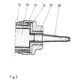
- FIG. 3 shows a gun nozzle 3, in which the multi-purpose gun works with material 19, which is located in standardized, disposable material packs 16.
- the second pressure chamber 13 and thus the secondary line 7 are closed by an adapter 29.
- a disposable standard nozzle 30 is used.
- larger containers for example canisters or barrels, which are arranged outside the gun can also be used.
Landscapes
- Engineering & Computer Science (AREA)
- Mechanical Engineering (AREA)
- Nozzles (AREA)
- Coating Apparatus (AREA)
Abstract
Description
- Die Erfindung betrifft eine Mehrzweckpistole zum Auftragen pastöser Materialien mit einem teilbaren, als Druckraum ausgebildeten Gehäuse zur Aufnahme einer das pastöse Material enthaltenden, austauschbaren Einwegpackung, mit einem Betätigungsgriff für ein Druckluftventil, das in einer Druckluftzuleitung zum Druckraum angeordnet ist und mit einer Materialaustrittsdüse.
- Druckluftbetätigte Pistolen zum Auftragen pastöser Materialien, beispielsweise Dichtmassen für Kraftfahrzeuge, sind bekannt. Dabei werden Einwegpackungen, die als Kartuschen oder als Kunststoff-Presspackungen ausgebildet sind und das pastöse Material enthalten, in einen Druckraum eingelegt. Die dort anstehende Druckluft beaufschlagt die jeweilige Packung und bewirkt den Materialaustritt durch eine Austrittsdüse.Entsprechend der eingestellten Druckhöhe erfolgt durch die manuelle Betätigung eines Ventils in zusätzlicher Abhängigkeit von der Konsistenz des verarbeiteten Materials die Abgabe einer bestimmten Materialmenge pro Zeiteinheit. Dabei wird das Material fadenförmig auf die abzudichtende Fläche aufgetragen. Nach dem Auftrag muß ein flächiges Verteilen des aufgetragenen Strangs oder Fadens von Hand vorgenommen werden. Eine dünnflächige, gleichmäßige Auftragung des Materials ist sehr schwierig und von der Geschicklichkeit des Monteurs abhängig.
- Ausgehend von diesem Stand der Technik liegt der Erfindung die Aufgabe zugrunde, eine Mehrzweckpistole zu schaffen, welche alternativ zwei Arbeitsvorgänge ermöglicht, nämlich einerseits den strangförmigen oder fadenförmigen Austritt des pastösen Materials, den man als "Spritzen" bezeichnet und andererseits einen flächigen Austritt,der als "Sprühen" bezeichnet wird.
- Zur Lösung dieser Aufgabe weist die Mehrzweckpistole einen zweiten Druckraum auf, der wie der erste, die Einwegpackung enthaltende Druckraum, mit Druckluft beschickbar ist und der in eine die Materialaustrittsdüse zumindest teilweise umgreifende Luftaustrittsdüse mit einem Mischraum für ein Mischen von pastösem Material und Luft mündet, aus dem das gegebenenfalls mit Luft vermischte Material austritt, wobei die in die Luftaustrittsdüse und den Mischraum gelangende Luftmenge einstellbar ist.
- Bei einer bevorzugten Ausführungsform sind der erste Druckraum und der zweite Druckraum pneumatisch parallelgeschaltet.
- Die Aufgabe des zweiten Druckraums und der sich anschliessenden Austrittsorgane besteht darin, das aus dem ersten Druckraum austretende pastöse Material beim Austritt aus der ersten Materialdüse so mit pneumatischer Energie der zutretenden Druckluft zu beaufschlagen, daß das pastöse genommen werden. Eine dünnflächige, gleichmäßige Auftragung des Materials ist sehr schwierig und von der Geschicklichkeit des Monteurs abhängig.
- Ausgehend von diesem Stand der Technik liegt der Erfindung die Aufgabe zugrunde, eine Mehrzweckpistole zu schaffen, welche alternativ zwei Arbeitsvorgänge ermöglicht, nämlich einerseits den strangförmigen oder fadenförmigen Austritt des pastösen Materials, den man als "Spritzen" bezeichnet und andererseits einen flächigen Austritt, der als "Sprühen" bezeichnet wird.
- Zur Lösung dieser Aufgabe weist die Mehrzweckpistole einen zweiten Druckraum auf, der wie der erste, die Einwegpackung enthaltende Druckraum, mit Druckluft beschickbar ist und der in eine die Materialaustrittsdüse zumindest teilweise umgreifende Luftaustrittsdüse mit einem Mischraum für ein Mischen von pastösem Material und Luft mündet, aus dem das gegebenenfalls mit Luft vermischte Material austritt, wobei die in die Luftaustrittsdüse und den Mischraum gelangende Luftmenge einstellbar ist.
- Bei einer bevorzugten Ausführungsform sind der erste Druckraum und der zweite Druckraum pneumatisch parallelgeschaltet. Die Aufgabe des zweiten Druckraums und der sich anschlies
- senden Austrittsorgane besteht darin, das aus dem ersten Druckraum austretende pastöse Material beim Austritt aus der ersten Materialdüse so mit pneumatischer Energie der zutretenden Druckluft zu beaufschlagen, daß das pastöse Material mit Druckluft vermischt, zerteilt und beschleunigt wird und daß sich eine feine, bei Bedarf dünnschichtige Verteilung in Form eines Materialfilms auf der zu dichtenden Fläche ergibt. Durch die entsprechende Anordnung und Betätigung einer Absperreinrichtung oder Betätigungseinrichtung kann wahlweise während des unmittelbaren Hantierens mit der Pistole die zum zweiten Druckraum zutretende Druckluft zu- und abgeschaltet werden, so daß eine Mehrzweckverwendung der Pistole möglich ist.
- Damit die pneumatischen Toträume möglichst klein gehalten werden und demzufolge nach Beendigung des Materialauftrags eine sehr schnelle Druckentlastung möglich ist, sind der erste und zweite Druckraum pneumatisch getrennt. Die Expansion wird dabei auf den maßgeblichen ersten Druckraum beschränkt.
- Bei einer bevorzugten Ausführungsform der Erfindung ist konzentrisch zu dem ersten Druckraum und dem zweiten Druckraum ein Drucklosraum angeordnet, der mittels einer Dichtung abgedichtet wird, die zwischen dem Außendurchmesser und der kreiszylindrischen Einweg-Materialpackung und dem Innendurchmesser des ersten Druckraums angeordnet ist. Der Drucklosraum umgibt also die Einwegpackung.
- In einem zylindrisch ausgebildeten ersten Druckraum ist die zylindrische Einwegpackung untergebracht. Ein Folgekolben befördert bei einer Druckbeaufschlagung deren Material zu einer Materialaustrittsdüse. Diese bildet mit dem Gehäuseboden eine Baueinheit und ist über ein Gewinde leicht austauschbar.
- Vor beiden pneumatischen Druckräumen ermöglicht ein Handgriff eine Einhandbedienung. In diesem Handgriff befindet sich ein manueller Abzugsbügel mit einem 3/2-Sitzventil, dem beide Druckluftstränge nachgeschaltet sind. Dem Primärstrang ist ein einstellbares Druckluftreduzierventil nachgeschaltet. Die beiden Ventile sind zu einer kompakten Ventil-Baueinheit zusammengefaßt. Im gleichen Primärstrang, unmittelbar vor dem ersten Druckraum oder Primärdruckraum, ist ein pneumatisch betätigtes 3/2-Sitzventil im Gehäuse integriert, das in seiner Ruhestellung die Entlastung der Druckluft aus dem ersten Druckraum bewirkt.
- Die wesentlichen Merkmale der Erfindung liegen in der Gestaltung, Anordnung und Betätigung einer Druckluft- Absperreinrichtung für den zweiten Druckstrang. In der geschlossenen Stellung der Druckluftabsperreinrichtung wird gespritzt, in der geöffneten wird gesprüht. Die Betätigung der Druckluftabsperrvorrichtung erfolgt durch eine Drehbewegung der austauschbaren Düse mit einem Verstellgewinde, welches die axiale und konzentrische Verschiebung zur Materialaustrittsdüse bewirkt. In einer Endstellung "Spritzen" wird die konische Innendichtfläche gegen eine Kante des Gehäusebodens gedrückt und verhindert den Austritt der Sekundärluft. In der Stellung "Sprühen" wird sie so weit geöffnet, daß sich das gewünschte Sprühbild ergibt. Die Vermischung des pastösen Materials mit der Sprühluft, und damit der Energieaustausch, erfolgen im Austrittsbereich der Luftaustrittsdüse. Zur Erzielung eines konzentrischen Ringspalts wird die innere Fläche der Luftaustrittsdüse auf der Außenfläche der Materialaustrittsdüse geführt. Zur Abdichtung der sekundären Druckluft gegenüber der äußeren Umgebung besitzt die Luftaustrittsdüse hinter ihrem Verstellgewinde eine elastische Dichtung gegenüber dem Gehäusekopf. Die Dichtung und die Luftaustrittsdüse bilden eine austauschbare Baueinheit.
- Nachstehend werden bevorzugte Ausführungsformen der Erfindung anhand der Zeichnung im einzelnen beschrieben. Es zeigen:
- Figur 1
- - einen pneumatischen Schaltplan der Mehrzweckpistole,
- Figur 2
- - eine bevorzugte Ausführungsform der Mehrzweckpistole im Längsschnitt,
- Figur 3
- - den Austrittsbereich der Mehrzweckpistole lediglich mit Materialaustrittsdüse.
- Die gesamte Mehrzweckpistole ist in Figur 1 mit dem Bezugszeichen 1 versehen. Sie weist eine Druckluftleitung 17 auf, in der ein 3/2-Sitzventil 9 für die Druckluft angeordnet ist. Hinter dem 3/2-Sitzventil 9 teilt sich der Druckluftstrom in einen eine Leitung 2 enthaltenden Primärstrang, der die Materialförderung bewirkt und in einen eine Leitung 7 enthaltenden Sekundärstrang für die Mehrzweckfunktion der Düsen 24 und 26. Im Primärstrang ist ein mechanisch einstellbares Druckluftreduzierventil 4 angeordnet. Die beiden Ventile 9 und 4 bilden eine kompakte Ventilbaueinheit 10, die ihrerseits leicht aus der Mehrzweckpistole entnehmbar und austauschbar ist. Im Primärstrang 2 ist ein pneumatisch betätigtes 3/2-Sitzventil 5 angeordnet, das einerseits bei Betätigung der Mehrzweckpistole die Druckluftbeaufschlagung eines Folgekolbens 18 zur Förderung des Materials 19 freigibt, andererseits beim Loslassen eines Abzugbügels 33 der Mehrzweckpistole die unmittelbare Expansion der Druckluft über einen Schalldämpfer 6 bewirkt. Eine Einwegpackung 16 ist im Gehäuse 11 über eine Feder 20 axial druckdicht verspannt und radial mit einer Dichtung 15 gegenüber einem Drucklosraum 14 abgedichtet. Der Drucklosraum 14 ist seinerseits über eine Belüftungsbohrung 21 mit der Atmosphäre verbunden. Ein Anstichbolzen 22 bewirkt beim Einbringen in das Gehäuse 11 ein Öffnen der Einwegpackung 16. Hinter dem 3/2-Sitzventil 9 mündet die Leitung des Sekundärstrangs 7 in den zweiten Druckraum 13 des Gehäuses 11.
- Das pastöse Material 19 wird durch Beaufschlagung des ersten Druckraums über die Materialaustrittsdüse 24 in eine Mischzone 25 des zweiten Druckstrangs 7 mit der Druckluftdüse 26 geführt und tritt bei der Mündung 27 aus der Mehrzweckpistole aus. Durch die Druckluftabsperreinrichtung 8 kann der Druckluftstrom des Sekundärstrangs 7 in die Luftaustrittsdüse 26 manuell wahlweise zu- oder abgeschaltet werden.
- In Figur 2 ist die Mehrzweckpistole in ihrer konstruktiven Ausbildung dargestellt. Ein Druckluftanschluß 32 ist an einem Haltegriff 31 angeordnet. Mit einem Abzugsbügel 33 wird die Ventil-Baueinheit 10 mechanisch betätigt und damit erfolgt auch eine Betätigung der Mehrzweckpistole 1. Mit einem Drehknopf 34 wird das eingebaute Druckluftreduzierventil auf den gewünschten Luftdruck einjustiert. Der sich anschließende Primärstrang 2 weist den Primärkanal 35, das 3/2-Sitzventil 5 mit dem Schalldämpfer 6 und den Primärdruckraum oder ersten Druckraum 12 auf. Über dessen Folgekolben 18 der Einwegpackung 16 wird das pastöse Material 19 druckbeaufschlagt und über die Materialaustrittsdüse 24 und die Mischzone 25 der Mündung 27 zugeführt. Im ersten Druckraum 12 sind ein Anstichbolzen 22, welcher die Schutzfolie 36 der Einwegpackung 16 bei deren Einlegen in die Pistole durchsticht, eine Feder 20 und eine Dichtung 15 angeordnet. Konzentrisch zur Einwegpackung 16 ist hinter der Dichtung 17 ein Drucklosraum 14 mit einer Belüftungsbohrung 21 angeordnet.
- In Strömungsrichtung hinter der Ventilbaueinheit 10 ist der Sekundärstrang 7 angeordnet, der von einer Leitung, dem zweiten Druckraum 19, dem Ringkanal 29 und der Luftaustrittsdüse 26 gebildet wird. Der zweite Druckraum 13 besteht aus einem konzentrischen Druckraum 37 und einem stirnseitigen Druckraum 38. Mit 39 ist der Ringkanal der Luftaustrittsdüse 26 bezeichnet. Von dort strömt die Druckluft in die Mischzone 25. Durch ein Verstellgewinde 40 der als Einwegdüse ausgebildeten Materialaustrittsdüse 24 kann der Ringkanal 39 im Bereich der Druckluftabsperreinrichtung 8 mit einem Verstellgewinde 40 freigegeben oder verschlossen werden. Durch das Verstellen wird eingestellt, ob die Mehrzweckpistole mit oder ohne Sekundärluft arbeiten soll.
- In Figur 3 ist eine Pistolendüse 3 dargestellt, bei der die Mehrzweckpistole mit Material 19 arbeitet, das sich in standartisierten Einweg-Materialpackungen 16 befindet. Dabei wird durch einen Adapter 29 der zweite Druckraum 13 und damit der Sekundärstrang 7 verschlossen. Es wird eine Einwegstandarddüse 30 verwendet. Statt der relativ kleinen Einweg-Materialpackungen können auch größere Gebinde, beispielsweise Kanister oder Fässer, die außerhalb der Pistole angeordnet sind, verwendet werden.
Claims (9)
dadurch gekennzeichnet,
daß die Pistole (1) einen zweiten Druckraum (13) aufweist, der wie der erste, die Einwegpackung enthaltende Druckraum (12) mit Druckluft beschickbar ist, und der in eine die Materialaustrittsdüse (24) zumindest teilweise umgreifende Luftaustrittsdüse (26) mit einem Mischraum (25) für ein Mischen von pastösem Material und Luft mündet, aus dem das gegebenenfalls mit Luft vermischte Material austritt, wobei die in die Luftaustrittsdüse (26) und den Mischraum (25) gelangende Luftmenge einstellbar ist.
dadurch gekennzeichnet,
daß der erste Druckraum (12) und der zweite Druckraum (13) pneumatisch parallelgeschaltet sind. reduzierventil (4) und ein pneumatisch betätigtes 3/5-Sitzventil (5) vorgesehen ist, das austrittsseitig mit einem Schalldämpfer (6) versehen ist.
dadurch gekennzeichnet,
daß vor den von einer Leitung (17) abzweigenden Druckluftleitungen (2; 7) ein mechanisch betätigbares 3/2-Sitzventil (9) als Hauptabsperreinrichtung vorgesehen ist.
dadurch gekennzeichnet,
daß konzentrisch zu dem ersten Druckraum (12) und dem zweiten Druckraum (13) ein Drucklosraum (14) angeordnet ist, der mittels einer Dichtung (15) abgedichtet wird, die zwischen dem Außendurchmesser der kreiszylindrischen Einweg-Materialpackung (16) und dem Innendurchmesser des ersten Druckraums (12) angeordnet ist.
dadurch gekennzeichnet,
daß das mechanisch einstellbare Druckluftreduzierventil (4) und das mechanisch betätigbare, als Hauptabsperreinrichtung dienende 3/2-Sitzventil (9) in einer aus dem Gehäuse (11) entnehmbaren Ventil-Baueinheit (10) integriert sind.
dadurch gekennzeichnet,
daß die Materialpackung (16) koaxial im Gehäuse (11) angeordnet und durch eine Druckfeder (20) und einen Federteller (28) vorgespannt sind.
dadurch gekennzeichnet,
daß im ersten Druckraum (12) des Gehäuses (11) ein Anstichbolzen (22) angeordnet ist.
dadurch gekennzeichnet,
daß die Materialaustrittsdüse (24) und/oder die Luftaustrittsdüse (26) ein Einschraubgewinde besitzt.
dadurch gekennzeichnet,
daß die Materialaustrittsdüse (24) und die Luftaustrittsdüse (26) als einheitliche, gegebenenfalls einteilige Pistolendüse (3) ausgebildet sind.
Applications Claiming Priority (4)
| Application Number | Priority Date | Filing Date | Title |
|---|---|---|---|
| DE9000957U DE9000957U1 (de) | 1990-01-29 | 1990-01-29 | Druckluftbetätigte Mehrzweckpistole zum Auftragen pastöser Materialien |
| DE9000957U | 1990-01-29 | ||
| DE9011965U DE9011965U1 (de) | 1990-08-17 | 1990-08-17 | Druckluftgesteuerte und -betätigte Mehrzweckpistole zum Auftragen pastöser Materialien |
| DE9011965U | 1990-08-17 |
Publications (3)
| Publication Number | Publication Date |
|---|---|
| EP0440149A2 true EP0440149A2 (de) | 1991-08-07 |
| EP0440149A3 EP0440149A3 (en) | 1991-12-27 |
| EP0440149B1 EP0440149B1 (de) | 1994-07-27 |
Family
ID=25956157
Family Applications (1)
| Application Number | Title | Priority Date | Filing Date |
|---|---|---|---|
| EP91101101A Expired - Lifetime EP0440149B1 (de) | 1990-01-29 | 1991-01-29 | Druckluftgesteuerte und druckluftbetätigte Mehrzweckpistole zum Auftragen pastöser Materialien |
Country Status (3)
| Country | Link |
|---|---|
| EP (1) | EP0440149B1 (de) |
| DE (1) | DE59102296D1 (de) |
| ES (1) | ES2057611T3 (de) |
Cited By (2)
| Publication number | Priority date | Publication date | Assignee | Title |
|---|---|---|---|---|
| DE4216746A1 (de) * | 1992-05-21 | 1993-11-25 | Sika Chemie Gmbh | Vorrichtung für den Auftrag pastöser Massen mittels Druckluft |
| US5536531A (en) * | 1994-07-26 | 1996-07-16 | Minnesota Mining And Manufacturing Company | Applicator for shear thinning viscous coating materials |
Family Cites Families (2)
| Publication number | Priority date | Publication date | Assignee | Title |
|---|---|---|---|---|
| GB723721A (en) * | 1951-12-19 | 1955-02-09 | Tecalemib Ltd | A device for use in the atomisation and projection of viscous materials |
| US4174068A (en) * | 1978-11-07 | 1979-11-13 | Rudolph Robert L | Gun having disposable cartridge |
-
1991
- 1991-01-29 EP EP91101101A patent/EP0440149B1/de not_active Expired - Lifetime
- 1991-01-29 DE DE59102296T patent/DE59102296D1/de not_active Expired - Fee Related
- 1991-01-29 ES ES91101101T patent/ES2057611T3/es not_active Expired - Lifetime
Cited By (3)
| Publication number | Priority date | Publication date | Assignee | Title |
|---|---|---|---|---|
| DE4216746A1 (de) * | 1992-05-21 | 1993-11-25 | Sika Chemie Gmbh | Vorrichtung für den Auftrag pastöser Massen mittels Druckluft |
| US5536531A (en) * | 1994-07-26 | 1996-07-16 | Minnesota Mining And Manufacturing Company | Applicator for shear thinning viscous coating materials |
| US5558277A (en) * | 1994-07-26 | 1996-09-24 | Minnesota Mining And Manufacturing Company | Applicator for shear thinning viscous coating materials |
Also Published As
| Publication number | Publication date |
|---|---|
| ES2057611T3 (es) | 1994-10-16 |
| EP0440149B1 (de) | 1994-07-27 |
| DE59102296D1 (de) | 1994-09-01 |
| EP0440149A3 (en) | 1991-12-27 |
Similar Documents
| Publication | Publication Date | Title |
|---|---|---|
| DE2742791C2 (de) | Abgabepistole für Schaumprodukte | |
| DE3503384C1 (de) | Spritzpistole für Beschichtungsmaterial | |
| DE4230535C2 (de) | Zweikomponenten-Spritzpistole | |
| EP0213073B1 (de) | Vorrichtung zum Mischen und Auftragen von flüssigen und/oder pastösen Substanzen | |
| EP0160786B1 (de) | Austreibvorrichtung für einen für hochviskoses Füllgut bestimmten Abgabebehälter | |
| EP0254969A1 (de) | Vorrichtung zum strangförmigen Austragen von pastösen Massen | |
| DE3025591A1 (de) | Elektrostatische spritzpistole | |
| DE10254409A1 (de) | Vorrichtung zum Mischen und Ausbringen von Mehrkomponentenmassen | |
| CH671600A5 (de) | ||
| DE3409725C2 (de) | ||
| DE9011965U1 (de) | Druckluftgesteuerte und -betätigte Mehrzweckpistole zum Auftragen pastöser Materialien | |
| EP0477211A1 (de) | Autogenes flammspritzgerät zum flammspritzen von pulverförmigen werkstoffen bzw. spritzpulver. | |
| DE2110085A1 (de) | Verfahren und Vorrichtung zum Spritzen von Farbe oder dergleichen | |
| DE694940C (de) | Verfahren und Vorrichtung zum Sprengen von Gebirge | |
| EP0578934A1 (de) | Vorrichtung zum Behandeln von Werkstücken mit einem Druckfluid | |
| EP0440149B1 (de) | Druckluftgesteuerte und druckluftbetätigte Mehrzweckpistole zum Auftragen pastöser Materialien | |
| DE9000957U1 (de) | Druckluftbetätigte Mehrzweckpistole zum Auftragen pastöser Materialien | |
| DE3723677A1 (de) | Vorrichtung zum mischen und dosierten auftragen zweier pastoeser massen | |
| DE69506413T2 (de) | Sprühpistole mit venturi im rohr | |
| DE3124125A1 (de) | Hochdruck-spruehpistole | |
| DE2954473A1 (de) | Sicherheitsbrenner zum pulverflammspritzen | |
| DE4026170A1 (de) | Druckluftgesteuerte und -betaetigte mehrzweckpistole zum auftragen pastoeser materialien | |
| DE3922958C2 (de) | Entleerglied | |
| DE3802519C2 (de) | Vorrichtung zur dosierten Abgabe von flüssigen oder fließfähigen, miteinander unter Bildung einer nichtfließfähigen Masse chemisch reagierenden Materialkomponenten | |
| DE3740817C2 (de) |
Legal Events
| Date | Code | Title | Description |
|---|---|---|---|
| PUAI | Public reference made under article 153(3) epc to a published international application that has entered the european phase |
Free format text: ORIGINAL CODE: 0009012 |
|
| AK | Designated contracting states |
Kind code of ref document: A2 Designated state(s): DE ES FR GB IT |
|
| PUAL | Search report despatched |
Free format text: ORIGINAL CODE: 0009013 |
|
| AK | Designated contracting states |
Kind code of ref document: A3 Designated state(s): DE ES FR GB IT |
|
| 17P | Request for examination filed |
Effective date: 19920219 |
|
| 17Q | First examination report despatched |
Effective date: 19930611 |
|
| GRAA | (expected) grant |
Free format text: ORIGINAL CODE: 0009210 |
|
| AK | Designated contracting states |
Kind code of ref document: B1 Designated state(s): DE ES FR GB IT |
|
| GBT | Gb: translation of ep patent filed (gb section 77(6)(a)/1977) |
Effective date: 19940726 |
|
| REF | Corresponds to: |
Ref document number: 59102296 Country of ref document: DE Date of ref document: 19940901 |
|
| ET | Fr: translation filed | ||
| REG | Reference to a national code |
Ref country code: ES Ref legal event code: FG2A Ref document number: 2057611 Country of ref document: ES Kind code of ref document: T3 |
|
| ITF | It: translation for a ep patent filed | ||
| PLBE | No opposition filed within time limit |
Free format text: ORIGINAL CODE: 0009261 |
|
| STAA | Information on the status of an ep patent application or granted ep patent |
Free format text: STATUS: NO OPPOSITION FILED WITHIN TIME LIMIT |
|
| 26N | No opposition filed | ||
| PGFP | Annual fee paid to national office [announced via postgrant information from national office to epo] |
Ref country code: GB Payment date: 19990118 Year of fee payment: 9 |
|
| PGFP | Annual fee paid to national office [announced via postgrant information from national office to epo] |
Ref country code: FR Payment date: 19990119 Year of fee payment: 9 |
|
| PGFP | Annual fee paid to national office [announced via postgrant information from national office to epo] |
Ref country code: ES Payment date: 19990121 Year of fee payment: 9 |
|
| PG25 | Lapsed in a contracting state [announced via postgrant information from national office to epo] |
Ref country code: GB Free format text: LAPSE BECAUSE OF NON-PAYMENT OF DUE FEES Effective date: 20000129 |
|
| PG25 | Lapsed in a contracting state [announced via postgrant information from national office to epo] |
Ref country code: ES Free format text: LAPSE BECAUSE OF NON-PAYMENT OF DUE FEES Effective date: 20000131 |
|
| GBPC | Gb: european patent ceased through non-payment of renewal fee |
Effective date: 20000129 |
|
| PG25 | Lapsed in a contracting state [announced via postgrant information from national office to epo] |
Ref country code: FR Free format text: LAPSE BECAUSE OF NON-PAYMENT OF DUE FEES Effective date: 20000929 |
|
| REG | Reference to a national code |
Ref country code: FR Ref legal event code: ST |
|
| REG | Reference to a national code |
Ref country code: ES Ref legal event code: FD2A Effective date: 20010910 |
|
| PG25 | Lapsed in a contracting state [announced via postgrant information from national office to epo] |
Ref country code: IT Free format text: LAPSE BECAUSE OF NON-PAYMENT OF DUE FEES;WARNING: LAPSES OF ITALIAN PATENTS WITH EFFECTIVE DATE BEFORE 2007 MAY HAVE OCCURRED AT ANY TIME BEFORE 2007. THE CORRECT EFFECTIVE DATE MAY BE DIFFERENT FROM THE ONE RECORDED. Effective date: 20050129 |
|
| PGFP | Annual fee paid to national office [announced via postgrant information from national office to epo] |
Ref country code: DE Payment date: 20081223 Year of fee payment: 19 |
|
| PG25 | Lapsed in a contracting state [announced via postgrant information from national office to epo] |
Ref country code: DE Free format text: LAPSE BECAUSE OF NON-PAYMENT OF DUE FEES Effective date: 20100803 |