EP0439487B1 - Funktionsregelungsanordnung bei maschinen - Google Patents
Funktionsregelungsanordnung bei maschinen Download PDFInfo
- Publication number
- EP0439487B1 EP0439487B1 EP89911628A EP89911628A EP0439487B1 EP 0439487 B1 EP0439487 B1 EP 0439487B1 EP 89911628 A EP89911628 A EP 89911628A EP 89911628 A EP89911628 A EP 89911628A EP 0439487 B1 EP0439487 B1 EP 0439487B1
- Authority
- EP
- European Patent Office
- Prior art keywords
- control device
- interface
- control means
- amplifier
- designed
- Prior art date
- Legal status (The legal status is an assumption and is not a legal conclusion. Google has not performed a legal analysis and makes no representation as to the accuracy of the status listed.)
- Expired - Lifetime
Links
- 230000000881 depressing effect Effects 0.000 claims abstract description 9
- 238000009958 sewing Methods 0.000 claims abstract description 8
- 230000035945 sensitivity Effects 0.000 claims abstract description 5
- 239000007788 liquid Substances 0.000 claims abstract description 3
- 239000004753 textile Substances 0.000 claims abstract 2
- 238000007664 blowing Methods 0.000 claims description 6
- 239000012080 ambient air Substances 0.000 claims description 3
- 239000004020 conductor Substances 0.000 claims 1
- 238000006243 chemical reaction Methods 0.000 abstract 1
- 230000000994 depressogenic effect Effects 0.000 abstract 1
- 230000000712 assembly Effects 0.000 description 2
- 238000000429 assembly Methods 0.000 description 2
- 238000005553 drilling Methods 0.000 description 2
- 238000004519 manufacturing process Methods 0.000 description 2
- 239000003570 air Substances 0.000 description 1
- 230000015572 biosynthetic process Effects 0.000 description 1
- 238000010276 construction Methods 0.000 description 1
Images


Classifications
-
- G—PHYSICS
- G05—CONTROLLING; REGULATING
- G05B—CONTROL OR REGULATING SYSTEMS IN GENERAL; FUNCTIONAL ELEMENTS OF SUCH SYSTEMS; MONITORING OR TESTING ARRANGEMENTS FOR SUCH SYSTEMS OR ELEMENTS
- G05B19/00—Programme-control systems
- G05B19/02—Programme-control systems electric
- G05B19/04—Programme control other than numerical control, i.e. in sequence controllers or logic controllers
- G05B19/10—Programme control other than numerical control, i.e. in sequence controllers or logic controllers using selector switches
- G05B19/106—Programme control other than numerical control, i.e. in sequence controllers or logic controllers using selector switches for selecting a programme, variable or parameter
- G05B19/108—Programme control other than numerical control, i.e. in sequence controllers or logic controllers using selector switches for selecting a programme, variable or parameter characterised by physical layout of switches; switches co-operating with display; use of switches in a special way
-
- D—TEXTILES; PAPER
- D05—SEWING; EMBROIDERING; TUFTING
- D05B—SEWING
- D05B69/00—Driving-gear; Control devices
- D05B69/14—Devices for changing speed or for reversing direction of rotation
- D05B69/18—Devices for changing speed or for reversing direction of rotation electric, e.g. foot pedals
-
- G—PHYSICS
- G05—CONTROLLING; REGULATING
- G05B—CONTROL OR REGULATING SYSTEMS IN GENERAL; FUNCTIONAL ELEMENTS OF SUCH SYSTEMS; MONITORING OR TESTING ARRANGEMENTS FOR SUCH SYSTEMS OR ELEMENTS
- G05B19/00—Programme-control systems
- G05B19/02—Programme-control systems electric
- G05B19/04—Programme control other than numerical control, i.e. in sequence controllers or logic controllers
- G05B19/07—Programme control other than numerical control, i.e. in sequence controllers or logic controllers where the programme is defined in the fixed connection of electrical elements, e.g. potentiometers, counters, transistors
- G05B19/075—Programme control other than numerical control, i.e. in sequence controllers or logic controllers where the programme is defined in the fixed connection of electrical elements, e.g. potentiometers, counters, transistors for delivering a step function, a slope or a continuous function
Definitions
- the present invention relates to a functional control device of the type set forth in the preamble of patent claim 1.
- US-A-4 261 273 relates to a pneumatic speed control device, designed for a sewing machine.
- This control device is actuated by means of a pneumatic breaker, which successively closes a plurality of contacts concurrently with an air pressure increase before the breaker, without any spark formation at the contacts.
- This control device is integrated with the sewing machine and is designed to directly actuate a machine function, namely the motor speed, but merely in one direction, namely forwardly or with a speed increase. No flexibility or adjustment as to different machines or machine types can be achieved by means of this control device. It is difficult or quite impossible to perform a pressure sensitivity and zero adjustment in practice. To use a plurality of movable parts results of course in a substantial disturbance sensitivity as well as elevated production and assembly costs.
- the control device is not conducive to making it easier for handicaped persons, and large foot movements are required in order to perform substantial speed changes.
- the used sensor which is an entirely mechanical construction, is utterly objectionable for this purpose.
- a direct control using a high voltage is also an inconvenience.
- US-A-4 722 288 relates to an electric sewing machine having an integrated computer designed to program needle work designs. Also, in this case the control device is integrated and cannot be separated from the machine to be controlled.
- the foot pedal described in this document, is used solely to initiate and stop respectively a programmed or preprogrammed work operation, and it is not, like the document discussed above, conducive to helping a handicaped person, and large control movements are necessary.
- the purpose of the present invention is to avoid the above-mentioned drawbacks and suggest a functional control device, which can be easily and simply adapted and connected to different machines in general terms and to different motor control means in particular, and which also is conducive to assisting a handicaped person, is simple, can be quickly and inexpensively produced and assembled and takes ergonomic and production engineering requirements into consideration, e.g. so called standing sewing operations.
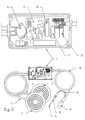
- reference numeral 1 denotes a functional control device according to the invention in its entirety
- 2 and 3 denote foot bellows
- a suction and/or blowing nozzle 4 can be used.
- Hose pipes 5 and 6 connect said bellows to an interface box 7, in which a piezo-electric sensor 8 is actuated by means of pressure fluctuations in the medium in parts 2-6, which medium can be a gas or a liquid.
- a suction or blowing nozzle is used, said medium is of course the ambient air.
- the piezo-electric sensor 8 is designed to generate an analogous output signal, which is amplified in an amplifier 9 and enters an analog/digital converter 10.
- the digital signal enters a memory 11, in which the digital signal is converted to a control code, which is adapted to the respective motor control means and can be a so called grey code, or possibly an inverted grey code, or any digital code according to what is preferred as to the programming.
- the code obtained in this way, enters an output amplifier 12, which adapts the voltage level of the code to the one, which is suitable for the control work.
- An electric wire 13 then connects the box to an adapter 14 for the motor control means.
- the interface receives its electric power supply mainly from the motor control means, which suitably is run by means of a reduced voltage, e.g. 24 V.
- a separate connector 15 can for this purpose be connected in a wire 16, or a special wire, designed for such a power supply through adapter 14, can be connected in wire 13.
- the above-described configuration is shown in Figs. 2-4.
- Figs. 5 and 6 are designed for this purpose. According to these assemblies the signals are led from piezo-electric sensor 8 to an amplifier 17, which can have the same features as amplifier 9, described above, but which for practical reasons can be designed in a somewhat different way. See e.g. Fig. 10. The signal subsequently is divided and led to an amplifier 18 and a simple analog/digital converter 19. Amplifier 18 adapts the analogous signal to such a signal as is required by the motor control means.
- Converter 19 is designed with additional functions, e.g. start, stop, presser foot lifting or lowering, thread cutting and starting and stopping control signals. The amplifier controls the motor speed and a connection/interrelationship between amplifier 18 and converter 19 may exist.
- a functional control device is easy to use for controlling e.g. a sewing machine 20 or a drilling machine 21.
- the forward depressing movement comprises a presser foot and 12 speed steps or steplessly from zero to the maximum motor speed, e.g. 400-9000 rev./min., and a presser foot and a cutting and control function respectively.
- the function of the pressure interface and the electric interface respectively can easily be changed in a way known per se for various types of machine control means and different pressure sensitivities.
- the output signals can also be changed.
- a suction nozzle 4 In case a blowing is required in order to obtain an actuation, this nozzle can be connected to the other connection joint, shown in the drawings, which normally is e.g. plugged up. As an alternative this joint is open to the ambient air.
Landscapes
- Engineering & Computer Science (AREA)
- Physics & Mathematics (AREA)
- General Physics & Mathematics (AREA)
- Automation & Control Theory (AREA)
- Mechanical Engineering (AREA)
- Textile Engineering (AREA)
- Sewing Machines And Sewing (AREA)
- Control Of Multiple Motors (AREA)
- Heat Treatment Of Sheet Steel (AREA)
- Fixed Capacitors And Capacitor Manufacturing Machines (AREA)
- Selective Calling Equipment (AREA)
Claims (10)
- Funktionsregelungsanordnung für Maschinen, insbesondere Nähmaschinen und andere Maschinen der Textilmaschinenindustrie, welche Anordnung als Fernregelungsanordnung mittels zwei Fussbälgen oder Fusspedalen (2, 3) oder einem Saug- bzw. einem Blasmundstück (4) ausgeführt ist, wobei ein gasförmiges oder flüssiges Medium angewendet wird, um die Maschinenfunktion auszulösen, dadurch gekennzeichnet, dass genanntes Medium zum Betätigen einer Anpasschaltung (7) vorgesehen ist, wobei die Druckschwankungen der Regelungsanordnung (1) in einen der Machine angepassten Kode umgewandelt werden, dass genannte Regelungsanordnung pneumatische Fussbälge oder Fusspedale (2, 3) bzw. ein Saug- bzw. ein Blasmundstück (4) besitzt, die zu einem Anpasschaltungskasten (7) führen, welcher eine Nulleinstellung, einen Programmkreis und Kabel (13) für ein Signal zu bzw. von dem Motorregelungsmittel besitzt, dass bei Bedienen der Fussbälge oder Fusspedale einer von diesen eine vorwärts gerichtete absenkende Bewegung und der andere eine rückwärtsgerichtete absenkende Bewegung bewirkt, und dass bei Bedienen eines Mundstückes dieses den gleichen Funktionen entspricht.
- Funktionsregelungsanordnung nach Anspruch 1, dadurch gekennzeichnet, dass genannte vorwärtsgerichtete absenkende Bewegung einen nach unten gerichteten Pressfuss sowie die Geschwindigkeit des Motors in 12 Stufen oder stufenlos von Null bis Maximum beeinflusst, z.B. 400 - 9000 U/min, und dass genannte rückwärtsgerichtete absenkende Bewegung einen Pressfuss nach oben sowie eine Abschneide- bzw. Regelungsfunktion beeinflusst.
- Funktionsregelungsanordnung nach Anspruch 1, dadurch gekennzeichnet, dass die Funktion der Druckanpasschaltung bzw. der elektrischen Anpasschaltung (7) für verschiedene Arten von Maschinenregelungsmitteln und veschiedene Druckempfindlichkeiten einstellbar ist.
- Funktionsregelungsanordnung nach Anspruch 1, dadurch gekennzeichnet, dass die Outputsignale änderbar sind.
- Funktionsregelungsanordnung nach Anspruch 1, dadurch gekennzeichnet, dass bei Bedienung der Fusspedale (2, 3) es sich um genannte Bälge handelt, von denen Schläuche (5, 6) zu einem betreffenden Anschluss an dem Anpasschaltungskasten (7) führen, welche Schläuche genanntes Medium enthalten, und dass bei Anwendung eines Mundstückes (4) dieses an den Anpasschaltungskasten angeschlossen ist und einer der genannten Anschlüsse für eine Blasfunktion oder der andere genannter Anschlüsse für eine Saugfunktion vorgesehen ist unter Anwendung des gleichen Schlauches (5), und dass der nicht angewendete Anschluss verschlossen oder offengelassen ist, um mit der Umgebungsluft zu kommunizieren.
- Funktionsregelungsanordnung nach Anspruch 1, dadurch gekennzeichnet, dass genannte Fusspedale oder Fussbälge bzw. genanntes Mundstück (4) dazu vorgesehen sind, in genannter Anpasschaltung einen piezo-elektrischen Sensor (8) zu betätigen, welcher zur Erzeugung eines analogen Outputsignals vorgesehen ist, welches in einem Verstärker (9 bzw. 17) zum Verstärken vorgesehen ist.
- Funktionsregelungsanordnung nach Anspruch 6, dadurch gekennzeichnet, dass das genannte analoge Outputsignal in Verbindung mit genanntem Verstärker (9) zur Weitergabe an einen analog/digitalen Umwandler (10) vorgesehen ist, von welchem das Signal zur Weitergabe an einen Speicher (11) vorgesehen ist, worin das digitale Signal in einen Kontrollkode umwandelbar ist, welcher an das Regelungsmittel des genannten betreffenden Motors angepasst ist, bevorzugt ein sogenannter grauer Kode oder ein umgekehrter grauer Kode, wovon der auf diese Weise erhaltene Kode zu einem Outputsignalverstärker (12) zur Weitergabe vorgesehen ist, welcher den Spannungspegel des Kodes an den für genanntes Regelungsmittel erforderlichen anpasst, in Verbindung womit genanntes elektrisches Kabel (13) genannten Anpassungsschaltungskasten (7) mit einem Adapter (14) für genanntes Motorregelungsmittel verbindet.
- Funktionsregelungsanordnung nach Anspruch 6, dadurch gekennzeichnet, dass genanntes analoges Outputsignal im Zusammenhange mit genanntem Verstärker (17) zum Aufteilen und gleichzeitigen Weiterbefördern an einen Verstärker (18) bzw. einen einfachen analog/digitalen Unwandler (19) vorgesehen ist, dass der letztgenannte Verstärker (18) genanntes analoges Signal an ein Signal anpasst, welches für genanntes Motorregelungsmittel erforderlich ist, und dass genannter Konverter (19) zusätzliche Funktionen vorsieht, z.B. Start, Stopp, Pressfussanheben und -absenken, Fadenabschneiden sowie Starten und Stoppen von Regelungssignalen, und dass der genannte letztere Verstärker (18) zum Regeln der Motorgeschwindigkeit vorgesehen ist, und dass eine Verbindung oder Zwischenverbindung zwischen genanntem Verstärker (18) und genanntem Umwandler (19) vorgesehen ist.
- Funktionsregelungsanordnung nach Anspruch 1, dadurch gekennzeichnet, dass genannte Anpasschaltung (7) zur Versorgung mit elektrischer Kraft durch genanntes Motorregelungsmittel vorgesehen ist, welches bevorzugt durch reduzierte Spannung angetrieben ist.
- Funktionsregelungsanordnung nach Anspruch 9, dadurch gekennzeichnet, dass die elektrische Kraft zufuhr von genanntem Motorregelungsmittel an genannte Anpasschaltung über ein elektrisches Kabel (16) vorgesehen ist, wobei bevorzugt ein eingebauter Anschluss (15) vorgesehen ist, oder dass bei genanntem elektrischen Kabel (13) zwischen genannter Anpasschaltung und genanntem Motorregelungsmittel ein besonderer Leiter vorgesehen ist, welcher zur Weitergabe der Spannung an genannte Anpasschaltung durch genannten Adapter (14) vorgesehen ist.
Applications Claiming Priority (3)
| Application Number | Priority Date | Filing Date | Title |
|---|---|---|---|
| SE8803756 | 1988-10-20 | ||
| SE19888803756A SE8803756D0 (sv) | 1988-10-20 | 1988-10-20 | Fjaerrkontroll av maskinfunktioner med fotpedaler eller blaasmunstycke |
| PCT/SE1989/000576 WO1990004670A1 (en) | 1988-10-20 | 1989-10-19 | Function control device for machines |
Publications (2)
| Publication Number | Publication Date |
|---|---|
| EP0439487A1 EP0439487A1 (de) | 1991-08-07 |
| EP0439487B1 true EP0439487B1 (de) | 1994-06-08 |
Family
ID=20373694
Family Applications (1)
| Application Number | Title | Priority Date | Filing Date |
|---|---|---|---|
| EP89911628A Expired - Lifetime EP0439487B1 (de) | 1988-10-20 | 1989-10-19 | Funktionsregelungsanordnung bei maschinen |
Country Status (7)
| Country | Link |
|---|---|
| US (1) | US5227706A (de) |
| EP (1) | EP0439487B1 (de) |
| AT (1) | ATE106959T1 (de) |
| AU (1) | AU4420189A (de) |
| DE (1) | DE68916030D1 (de) |
| SE (1) | SE8803756D0 (de) |
| WO (1) | WO1990004670A1 (de) |
Families Citing this family (4)
| Publication number | Priority date | Publication date | Assignee | Title |
|---|---|---|---|---|
| US5587634A (en) * | 1994-11-29 | 1996-12-24 | Ara Electronics Corp. | Human body actuated control apparatus and system for commercial sewing machines |
| US6432203B1 (en) * | 1997-03-17 | 2002-08-13 | Applied Komatsu Technology, Inc. | Heated and cooled vacuum chamber shield |
| US20090005789A1 (en) * | 2007-06-26 | 2009-01-01 | Charles Steven T | Force Sensitive Foot Controller |
| WO2016122295A1 (es) * | 2015-01-27 | 2016-08-04 | Castro Baldenebro Brayan Gamaniel | Dispositivo inalámbrico controlador de maquinas de coser eléctricas |
Family Cites Families (14)
| Publication number | Priority date | Publication date | Assignee | Title |
|---|---|---|---|---|
| FR606578A (fr) * | 1925-02-25 | 1926-06-16 | Machine à écrire permettant de faire apparaître instantanément des caractères lumineux variables | |
| US3582748A (en) * | 1967-02-07 | 1971-06-01 | Janome Sewing Machine Co Ltd | Electric sewing machine with remote hand operated control |
| US3597672A (en) * | 1968-12-30 | 1971-08-03 | Singer Co | Electrical drive systems for sewing machines |
| US4280425A (en) * | 1979-07-09 | 1981-07-28 | Pce Corporation | Method and apparatus for electro-pneumatic control of a stitching machine |
| DE7539310U (de) * | 1975-12-10 | 1976-04-01 | Frankl & Kirchner, Fabrik Fuer Elektromotoren U. Elektrische Apparate, 6830 Schwetzingen | Einrichtung zur hoechststichzahlbegrenzung von naehmaschinen |
| CH606578A5 (en) * | 1976-04-15 | 1978-11-15 | Mefina Sa | Non-electrical control for sewing machine speed regulator |
| CH606579A5 (de) * | 1976-12-29 | 1978-11-15 | Mefina Sa | |
| CH620065A5 (de) * | 1977-12-01 | 1980-10-31 | Mefina Sa | |
| FR2458174A1 (fr) * | 1979-05-29 | 1980-12-26 | Artus | Dispositif pneumatique de commande de la vitesse d'un moteur electrique |
| US4413214A (en) * | 1981-11-12 | 1983-11-01 | The Singer Company | Vented pneumatic foot controller |
| US4583029A (en) * | 1984-07-06 | 1986-04-15 | The Babcock & Wilcox Company | Variable speed resistive network for a pneumatic servo assembly of an electro-pneumatic converter |
| JPS6137282A (ja) * | 1984-07-31 | 1986-02-22 | ジューキ株式会社 | ミシンの入力装置 |
| JPS61217197A (ja) * | 1985-03-20 | 1986-09-26 | ブラザー工業株式会社 | ミシン |
| US4969756A (en) * | 1990-03-19 | 1990-11-13 | General Motors Corporation | Motor driven actuator speed control |
-
1988
- 1988-10-20 SE SE19888803756A patent/SE8803756D0/xx unknown
-
1989
- 1989-10-19 EP EP89911628A patent/EP0439487B1/de not_active Expired - Lifetime
- 1989-10-19 AT AT89911628T patent/ATE106959T1/de not_active IP Right Cessation
- 1989-10-19 DE DE68916030T patent/DE68916030D1/de not_active Expired - Lifetime
- 1989-10-19 AU AU44201/89A patent/AU4420189A/en not_active Abandoned
- 1989-10-19 US US07/678,957 patent/US5227706A/en not_active Expired - Fee Related
- 1989-10-19 WO PCT/SE1989/000576 patent/WO1990004670A1/en not_active Ceased
Also Published As
| Publication number | Publication date |
|---|---|
| AU4420189A (en) | 1990-05-14 |
| WO1990004670A1 (en) | 1990-05-03 |
| ATE106959T1 (de) | 1994-06-15 |
| DE68916030D1 (de) | 1994-07-14 |
| US5227706A (en) | 1993-07-13 |
| SE8803756D0 (sv) | 1988-10-20 |
| EP0439487A1 (de) | 1991-08-07 |
Similar Documents
| Publication | Publication Date | Title |
|---|---|---|
| US4354838A (en) | Foot controller for dental instruments or the like | |
| EP0439487B1 (de) | Funktionsregelungsanordnung bei maschinen | |
| WO1999019892A8 (en) | Control device for providing a variable control signal to a fluid-supplying machine | |
| JPH03142072A (ja) | 電気スタッド溶接装置 | |
| EP0077788B1 (de) | Steuervorrichtung für einen antrieb | |
| JPS61246806A (ja) | ロボツト制御装置 | |
| EP0402654A3 (de) | Anschlussvorrichtung für den Anschluss elektrischer Verbraucher | |
| CN101138884A (zh) | 全自动注吹塑料中空成型机控制装置及其自动控制方法 | |
| KR900013157A (ko) | 건설기계용 조작제어방법 및 장치 | |
| CA2012222A1 (en) | Functional control device | |
| US5233278A (en) | Universal motor speed signal converter | |
| JPH0426459A (ja) | ミシンの押さえ金上昇装置 | |
| KR940003821B1 (ko) | 무선 컨트롤(Control)방식의 세탁기 | |
| JP2500056Y2 (ja) | 信号表示灯 | |
| JPS6394321A (ja) | リモ−ト電源制御方式 | |
| US4888537A (en) | Method of monitoring the end position of a controlling element and circuit arrangement for the carrying out of the method | |
| CN223061216U (zh) | 缝纫机调速装置及缝纫机 | |
| JPH082396B2 (ja) | ミシンの押え上げ制御装置 | |
| JPH0238705A (ja) | エア駆動機器制御装置 | |
| JPS6442703A (en) | Controller for simultaneous multiaxis controller | |
| KR940003760Y1 (ko) | 진공청소기의 구동 전원 분리 회로 | |
| JPS58155002U (ja) | プロセス制御装置 | |
| JPS643304A (en) | Driving controller for hydraulic machine | |
| JPH06105405B2 (ja) | 工作機械における制御用通信システム | |
| JPS63124491U (de) |
Legal Events
| Date | Code | Title | Description |
|---|---|---|---|
| PUAI | Public reference made under article 153(3) epc to a published international application that has entered the european phase |
Free format text: ORIGINAL CODE: 0009012 |
|
| 17P | Request for examination filed |
Effective date: 19910412 |
|
| AK | Designated contracting states |
Kind code of ref document: A1 Designated state(s): AT BE CH DE FR GB IT LI NL SE |
|
| 17Q | First examination report despatched |
Effective date: 19920928 |
|
| GRAA | (expected) grant |
Free format text: ORIGINAL CODE: 0009210 |
|
| AK | Designated contracting states |
Kind code of ref document: B1 Designated state(s): AT BE CH DE FR GB IT LI NL SE |
|
| PG25 | Lapsed in a contracting state [announced via postgrant information from national office to epo] |
Ref country code: IT Free format text: LAPSE BECAUSE OF FAILURE TO SUBMIT A TRANSLATION OF THE DESCRIPTION OR TO PAY THE FEE WITHIN THE PRESCRIBED TIME-LIMIT;WARNING: LAPSES OF ITALIAN PATENTS WITH EFFECTIVE DATE BEFORE 2007 MAY HAVE OCCURRED AT ANY TIME BEFORE 2007. THE CORRECT EFFECTIVE DATE MAY BE DIFFERENT FROM THE ONE RECORDED. Effective date: 19940608 Ref country code: FR Effective date: 19940608 Ref country code: BE Effective date: 19940608 Ref country code: AT Effective date: 19940608 Ref country code: NL Effective date: 19940608 |
|
| REF | Corresponds to: |
Ref document number: 106959 Country of ref document: AT Date of ref document: 19940615 Kind code of ref document: T |
|
| REF | Corresponds to: |
Ref document number: 68916030 Country of ref document: DE Date of ref document: 19940714 |
|
| PG25 | Lapsed in a contracting state [announced via postgrant information from national office to epo] |
Ref country code: SE Effective date: 19940908 |
|
| PG25 | Lapsed in a contracting state [announced via postgrant information from national office to epo] |
Ref country code: DE Effective date: 19940909 |
|
| PG25 | Lapsed in a contracting state [announced via postgrant information from national office to epo] |
Ref country code: GB Effective date: 19941019 |
|
| PG25 | Lapsed in a contracting state [announced via postgrant information from national office to epo] |
Ref country code: LI Effective date: 19941031 Ref country code: CH Effective date: 19941031 |
|
| EN | Fr: translation not filed | ||
| NLV1 | Nl: lapsed or annulled due to failure to fulfill the requirements of art. 29p and 29m of the patents act | ||
| PLBE | No opposition filed within time limit |
Free format text: ORIGINAL CODE: 0009261 |
|
| STAA | Information on the status of an ep patent application or granted ep patent |
Free format text: STATUS: NO OPPOSITION FILED WITHIN TIME LIMIT |
|
| 26N | No opposition filed | ||
| GBPC | Gb: european patent ceased through non-payment of renewal fee |
Effective date: 19941019 |
|
| REG | Reference to a national code |
Ref country code: CH Ref legal event code: PL |