EP0439433A1 - Pneumatisches Schieberventil - Google Patents
Pneumatisches Schieberventil Download PDFInfo
- Publication number
- EP0439433A1 EP0439433A1 EP91810048A EP91810048A EP0439433A1 EP 0439433 A1 EP0439433 A1 EP 0439433A1 EP 91810048 A EP91810048 A EP 91810048A EP 91810048 A EP91810048 A EP 91810048A EP 0439433 A1 EP0439433 A1 EP 0439433A1
- Authority
- EP
- European Patent Office
- Prior art keywords
- slide
- valve
- control
- pressure
- drive
- Prior art date
- Legal status (The legal status is an assumption and is not a legal conclusion. Google has not performed a legal analysis and makes no representation as to the accuracy of the status listed.)
- Granted
Links
Images

Classifications
-
- F—MECHANICAL ENGINEERING; LIGHTING; HEATING; WEAPONS; BLASTING
- F15—FLUID-PRESSURE ACTUATORS; HYDRAULICS OR PNEUMATICS IN GENERAL
- F15B—SYSTEMS ACTING BY MEANS OF FLUIDS IN GENERAL; FLUID-PRESSURE ACTUATORS, e.g. SERVOMOTORS; DETAILS OF FLUID-PRESSURE SYSTEMS, NOT OTHERWISE PROVIDED FOR
- F15B21/00—Common features of fluid actuator systems; Fluid-pressure actuator systems or details thereof, not covered by any other group of this subclass
- F15B21/08—Servomotor systems incorporating electrically operated control means
- F15B21/087—Control strategy, e.g. with block diagram
Definitions
- the invention relates to a pneumatic slide valve according to the preamble of independent claim 1.
- EP-A-0 288 719 has disclosed a control device for a pneumohydraulic power drive, the output variable of which is a feed movement of a piston rod which is carried out with a specific force and speed.
- this device has become freely programmable. This means that switching points, feed forces etc. are numerical can be precisely specified and thus improve the quality of the drive.
- the function of the facility remains unchanged; no matter in which function mode it is operated. It is and remains a pneumo-hydraulic feed drive.
- the invention has for its object to provide a control valve improved in terms of dynamics and slide stability.
- the object is achieved by the invention according to claim 1.
- the slide valve according to the invention can be switched from one operating mode to the other in any working position and shows a significantly higher dynamic range and a higher slide stability.
- the function of the slide valve according to the invention is thus clearly changed by switching the function modes.
- the pressure control gain can be achieved can be gradually adapted to an optimal overall system dynamic. With very good linearity and minimal hysteresis, the air can be vented very quickly. Good response sensitivity is achieved even at high flow rates.
- the slide valve according to the invention is further distinguished by a particularly compact design. Finally, this valve avoids undefined intermediate states when switching from one operating mode to the other. Further advantageous features result from the dependent claims and the following description.
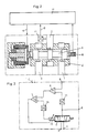
- the 3-way proportional pressure control valve shown in Fig. 1 consists essentially of a valve block 8 with two closure parts 9 and 10, a slide sleeve 6, a longitudinal slide 7 shown here in the middle position, a drive 13 and two sensors 11 and 16.
- Pressure control valve a valve is understood that regulates the pressure on the consumer side independently of pressure fluctuations in the line network and the size of the air consumption.
- the drive 13 is a moving coil drive and serves to move the slide 7 to regulate the pressure or the amount in its longitudinal direction.
- the drive has the function of a converter.
- the electrical manipulated variable is converted electromagnetically into a proportional force by the converter, which then moves the slide.
- the drive has a coil 12 which is connected to the slide and moves in an air gap of the iron core 14 of a permanent magnet. If an electrical current flows through the coil 12, a force is generated which is proportional to the current.
- One coil current direction pulls the coil 12 into the magnet and the other coil current direction pushes the coil out of the magnet.
- the magnet consists of the closure part 10, an iron core 14 and a permanent magnet 15.
- a pin 20 attached to the magnet extends through a cylindrical coil carrier 21 and prevents rotation.
- the slide combination with the longitudinal slide 7 and the slide bush 6 is flowed through radially and axially by the air.
- a supply connection 1 a working connection 2 and a ventilation connection 3 via ring channels 1c and 3b and a longitudinal bore 1b in the slide 7 and via passages 1a, 2a and 3a in the slide bush 6 connectable.
- Control edges on the middle path 22 of the slide 7 and the opposite edges of the slide sleeve 6 take over the air passage regulation.
- a small permanent magnet 16 ' is attached to the slide.
- This permanent magnet 16 ' protrudes into a bore 9' of the closure part 9.
- a Hall sensor 16 ⁇ measures the magnetic field surrounding it, which changes proportionally to the slide position.
- the Hall sensor 16 ⁇ is an analog sensor. It is built on a small ceramic substrate plate. This results in very small dimensions for the position sensor 16 compared to a linear potentiometer with a similar effect.
- the pressure sensor 11 is an analog, piezoresistive pressure sensor known per se. Under pressure, this sensor produces a change in resistance, which in turn produces an electrical voltage proportional to the change in pressure.
- the pressure sensor 11 is screwed to the valve block 8 with pins 11 '. The electrical voltage proportional to the pressure change is made available for processing in accordance with FIGS. 2 and 3 via line 19 of electronics 17.
- the valve mechanism works as follows: In order to increase the pressure, a voltage jump from 2 to 8 V, for example, is applied to the setpoint input B (FIG. 3). The electronics recognizes that the actual pressure value is too low and sends an electrical current surge into the coil 12, which then moves the slide 7 from the position 4 shown in FIG. 2 to the left into the ventilation position. Shortly before the desired pressure is reached, the electronics energize the coil 12, which pushes the slide back into the central position shown in FIG. 2.
- the setpoint is reset, for example to 2 V.
- the sequence is then analogous to that above, except that the slide 7 in FIG. 1 is now pushed to the right into the venting position.
- the longitudinal slide 7 is air-borne in the metallic sealing bush 6.
- the feed pressure is used, which passes from the longitudinal channel 1b via radial bores 4 in annular grooves 5 and from there between the sealing surfaces of the slide 7 and the bush 6.
- the drive 13, the slide combination 6 and 7, the sensors 11 and 16 and the control electronics 17 form a functional unit that belongs together and also Switching between pressure control valve and proportional directional control valve is possible during operation.
- the dynamics of the valve are influenced and controlled by several electronic control loops, for example as shown in FIG. 3.
- 11 denotes a pressure-voltage converter and 16 a position-voltage converter.
- the comparator A compares the signal of the converter 11 with the electrical pressure setpoint of the input B.
- a comparator D compares the output of the comparator A with the signal of the converter 16 and causes the slide 7 in the valve 13 to be displaced via the drive 13 of the valve E. one way or another.
- the converter 11 and the comparator A are switched off. As can be seen, there are no mechanical, but only electronic feedbacks in this valve.
- the inlet pressure P1 at 1 is preferably less than or equal to 12 bar and the working pressure P2 between 0 and 10 bar.
- the supply voltage at C is 24 V DC and the electrical pressure setpoint is between 0 and 10 V DC or 4 and 20 mA.
- An application example for the pressure control valve according to the invention is the ink metering of a printing press.
- the pressure at outlet 2 of the valve acts on the piston surface of the cylinder of a metering slide and generates one Pressure spring counteracting positioning force and thus a certain position of the metering slide.
- the ink layer thickness can be adjusted by changing the pressure setpoint on the pressure control valve.
- Other examples include the uniform unwinding of a paper roll with a controlled brake cylinder, the constant pressure of a roller in a rolling mill and the regulation of impacts and changes in mass in an air suspension with a rubber ball.
Landscapes
- Engineering & Computer Science (AREA)
- Chemical & Material Sciences (AREA)
- Analytical Chemistry (AREA)
- Physics & Mathematics (AREA)
- Fluid Mechanics (AREA)
- Mechanical Engineering (AREA)
- General Engineering & Computer Science (AREA)
- Magnetically Actuated Valves (AREA)
- Multiple-Way Valves (AREA)
- Servomotors (AREA)
- Pens And Brushes (AREA)
- Braking Systems And Boosters (AREA)
Abstract
Description
- Die Erfindung betrifft ein pneumatisches Schieberventil nach dem Oberbegriff des unabhängigen Patentanspruchs 1.
- Im Stand der Technik ist ein Steuerventil dieser Gattung durch die DE-A-32 21 928 und die DE-A-32 16 692 bekannt geworden.
- Ferner ist durch die EP-A-0 288 719 eine Steuereinrichtung für einen pneumohydraulischen Kraftantrieb bekannt geworden, dessen Ausgangsgrösse eine mit bestimmter Kraft und Geschwindigkeit ausgeführte Vorschubbewegung einer Kolbenstange ist.
- Aufgabe dieser Erfindung ist es, einen pneumohydraulischen Zylinder durch den gezielten Einsatz entsprechender Ventile, Sensoren, Druckluft und elektrischer Energie so anzusteuern, dass dem Zylinder die beiden folgenden unterschiedlichen Bewegungsarten eingeprägt werden können:
- a) Eilgang / Schnellgang
Es werden grosse Hübe mit grosser Geschwindigkeit und kleiner Betätigungskraft ausgeführt. - b) Schleichgang / Krafthub
Es werden kleine Hübe mit kleiner Geschwindigkeit und grosser Betätigungskraft ausgeführt. - Dank dem Einsatz von Servoventilen, Druck- und Wegsensoren ist diese Einrichtung frei programmierbar geworden. Das bedeutet, dass Umschaltpunkte, Vorschubkräfte etc. numerisch genau vorgegeben werden können und den Antrieb somit qualitativ verbessern. Die Funkion der Einrichtung bleibt aber unverändert; egal in welchem Funktionsmodus es betrieben wird. Es ist und bleibt ein pneumohydraulischer Vorschubantrieb.
- Der Erfindung liegt die Aufgabe zugrunde, ein bezüglich der Dynamik und der Schieberstabilität verbessertes Steuerventil zu schaffen. Die Aufgabe wird durch die Erfindung gemäss Anspruch 1 gelöst.
- Das erfindungsgemässe Schieberventil ist in jeder Arbeitslage von einem Betriebsmodus in den anderen umschaltbar und zeigt eine deutlich höhere Dynamik und eine höhere Schieberstabilität.
- Die beiden Funktionsmodi sind:
- a) Proportional-Wegeventil
Ein elektrischer Schieberpositionssollwert teilt dem Ventil mit, in welche Position der Ventilschieber bewegt werden soll. Am Ventilausgang wird sich dann ein Volumenstrom und ein Ausgangsdruck einstellen. Der Ausgangsdruck wird aber in diesem Betriebsmodus nicht geregelt. - b) Proportional-Druckregelventil
Ein elektrischer Drucksollwert teilt dem Ventil mit, welcher pneumatische Druck am Ausgang des Ventils eingeregelt werden soll. - Die Funktion des erfindungsgemässen Schieberventils wird also durch das Umschalten der Funktionsmodi eindeutig verändert. Zudem kann die Druckregelverstärkung zur Erzielung einer optimalen Gesamtsystem-Dynamik stufenweise angepasst werden. Bei sehr guter Linearität und minimaler Hysterese kann sehr schnell entlüftet werden. Auch bei hohem Durchfluss wird eine gute Ansprechempfindlichkeit erzielt. In konstruktiver Hinsicht zeichnet sich das erfindungsgemässe Schieberventil weiter durch eine besonders kompakte Bauweise aus. Schliesslich werden bei diesem Ventil beim Umschalten von einem Betriebsmodus in den anderen undefinierte Zwischenzustände vermieden. Weitere vorteilhafte Merkmale ergeben sich aus den abhängigen Ansprüchen und der nachfolgenden Beschreibung.
- Ein Ausführungsbeispiel der Erfindung wird nachfolgend anhand der Zeichnungen näher erläutert. Es zeigen:
- Fig. 1 ein erfindungsgemässes 3-Wege-Proportional-Druckregel-ventil im Längsschnitt,
- Fig. 2 eine schematisierte Darstellung des Regelventils, und
- Fig. 3 ein Schaltbild.
- Das in Fig. 1 gezeigte 3-Wege-Proportional-Druckregelventil besteht im wesentlichen aus einem Ventilblock 8 mit zwei Verschlussteilen 9 und 10, einer Schieberbüchse 6, einem hier in Mittelstellung gezeigten Längsschieber 7, einem Antrieb 13 und zwei Sensoren 11 und 16. Als Druckregelventil wird ein Ventil verstanden, dass den Druck auf der Verbraucherseite unabhängig von Druckschwankungen im Leitungsnetz und der Grösse des Luftverbrauches regelt.
- Der Antrieb 13 ist ein Tauchspulenantrieb und dient dazu, den Schieber 7 zur Regelung des Druckes oder der Menge in seiner Längsrichtung zu verschieben. Der Antrieb hat die Funktion eines Wandlers. Die elektrische Stellgrösse wird durch den Wandler elektromagnetisch in eine proportionale Kraft umgesetzt, welche dann den Schieber bewegt. Der Antrieb besitzt eine Spule 12, die mit dem Schieber verbunden ist und sich in einem Luftspalt des Eisenkerns 14 eines Dauermagneten bewegt. Fliesst ein elektrischer Strom durch die Spule 12, so entsteht eine zum Strom proportionale Kraft. Eine Spulenstromrichtung zieht die Spule 12 in den Magneten und die andere Spulenstromrichtung stösst die Spule aus dem Magneten. Der Magnet besteht aus dem Verschlussteil 10, einem Eisenkern 14 und einem Dauermagneten 15. Ein am Magnet befestigter Stift 20 greift durch einen zylindrischen Spulenträger 21 hindurch und verhindert eine Rotation.
- Die Schieberkombination mit dem Längsschieber 7 und der Schieberbüchse 6 wird von der Luft radial und axial durchflossen. In an sich bekannter Weise sind ein Versorgungsanschluss 1, ein Arbeitsanschluss 2 und ein Entlüftungsanschluss 3 über Ringkanäle 1c und 3b sowie einer Längsbohrung 1b im Schieber 7 sowie über Durchlässe 1a, 2a und 3a in der Schieberbüchse 6 verbindbar. Steuerkanten am Mittelweg 22 des Schiebers 7 und die gegenüberliegenden Kanten der Schieberbüchse 6 übernehmen die Luftdurchlass-Regulierung.
- Zur Erfassung der Position des Schiebers 7 ist auf dem Schieber ein kleiner Dauermagnet 16′ befestigt. Dieser Dauermagnet 16′ ragt in eine Bohrung 9′ des Verschlussteils 9. In der Bohrung 9′ misst ein Hallsensor 16˝ das ihn umgebende Magnetfeld, welches sich proportional zur Schieberstellung verändert. Der Hallsensor 16˝ ist ein analoger Sensor. Er ist auf einem kleinen Keramiksubstrat-Plättchen aufgebaut. Dadurch erhält man, im Vergleich zu einem ähnlich wirkenden Linear-Potentiometer, sehr kleine Abmessungen für den Positionssensor 16.
- Der Drucksensor 11 ist ein an sich bekannter analoger, piezoresistiver Drucksensor. Unter Druckeinwirkung ergibt sich an diesem Sensor eine Widerstandsänderung, die wiederum eine der Druckänderung proportionale elektrische Spannung ergibt. Der Drucksensor 11 ist mit Stiften 11′ am Ventilblock 8 angeschraubt. Die der Druckänderung proportionale elektrische Spannung wird gemäss den Fig. 2 und 3 über die Leitung 19 der Elektronik 17 zur Aufbereitüng zur Verfügung gestellt.
- Die Ventilmechanik arbeitet wie folgt: Um den Druck zu vergrössern, wird am Sollwerteingang B (Fig. 3) ein Spannungssprung von beispielsweise 2 auf 8 V angelegt. Die Elektronik erkennt, dass der Druckistwert zu klein ist und schickt einen elektrischen Stromstoss in die Spule 12, welche dann den Schieber 7 aus der in Fig. 2 gezeigten Stellung 4 nach links in die Belüftungs-Stellung bewegt. Kurz bevor der gewünschte Druck erreicht ist, bestromt die Elektronik die Spule 12, welche den Schieber wieder in die in Fig. 2 gezeigte Mittelstellung schiebt.
- Um den Druck zu verkleinern, wird der Sollwert zurück, beispielsweise auf 2 V gesetzt. Der Ablauf ist dann analog wie oben, ausser dass nun der Schieber 7 in Fig. 1 nach rechts in die Entlüftungs-Stellung geschoben wird.
- Zur Ausführung dieser Bewegungen ist der Längsschieber 7 in der metallisch dichtenden Büchse 6 luftgelagert. Verwendet wird hierzu der Speisedruck, der vom Längskanal 1b über radiale Bohrungen 4 in Ringnuten 5 und von dort zwischen die Dichtungsflächen des Schiebers 7 und der Büchse 6 gelangt. Bei unbedeutendem Luftverlust wird damit eine einfache und besonders verschleissarme Lagerung erreicht.
- Wesentlich ist, dass der Antrieb 13, die Schieberkombination 6 und 7, die Sensoren 11 und 16 und die Regelelektronik 17 eine zusammengehörende Funktionseinheit bilden und auch während des Betriebes ein Umschalten zwischen Druckregelventil und Proportionalwegeventil möglich ist. Beeinflusst und kontrolliert wird die Dynamik des Ventils durch mehrere elektronische Reglerschleifen, beispielsweise wie in Fig. 3 gezeigt. Im Schaltbild nach Fig. 3 sind mit 11 ein Druck-Spannungswandler und mit 16 ein Positions-Spannungswandler bezeichnet. Im Druckregelbetrieb vergleicht der Komparator A das Signal des Wandlers 11 mit dem elektrischen Drucksollwert des Eingangs B. Ein Komparator D vergleicht den Ausgang des Komparator A mit dem Signal des Wandlers 16 und bewirkt über dem Antrieb 13 des Ventils E eine Verschiebung des Schiebers 7 in der einen oder anderen Richtung. Beim Betrieb als Proportionalwegeventil sind der Wandler 11 und der Komparator A ausgeschaltet. Wie ersichtlich gibt es in diesem Ventil keine mechanischen, sondern nur elektronische Rückführungen.
- Der Eingangsdruck P1 bei 1 ist vorzugsweise kleiner gleich 12 bar und der Arbeitsdruck P2 zwischen 0 und 10 bar. Die Versorgungsspannung beträgt bei C 24 V DC und der elektrische Drucksollwert liegt zwischen 0 und 10 V DC, bzw. 4 und 20 mA.
- Ein Anwendungsbeispiel für das erfindungsgemässe Druckregelventil ist die Farbdosierung einer Druckmaschine. Hierbei wirkt der Druck am Ausgang 2 des Ventils auf die Kolbenfläche des Zylinders eines Dosierschiebers und erzeugt eine einen Druckfeder entgegenwirkende Stellkraft und damit eine bestimmte Stellung des Dosierschiebers. Dadurch wird ein gleichmässiger Farbauftrag von der Farbwalze mitgenommen. Die Farbschicht -Dicke kann durch eine Aenderung des Drucksollwertes am Druckregelventil verstellt werden. Weitere Bespiele sind das gleichmässige Abspulen einer Papierrolle mit einem geregelten Bremszylinder, das Konstanthalten des Druckes einer Walze eines Walzwerkes sowie das Ausregeln von Schlägen und Massenänderungen bei einer Luftfederung mit Gummiball.
Claims (4)
- Pneumatisches Schieberventil, mit einem Antrieb (13), mit dem über einen Regelkreis der Schieber (7) zur Luftdruck-Regulierung axial verschiebbar ist, dadurch gekennzeichnet, dass das Ventil einen Drucksensor (11) zur Erfassung des Arbeitsdruckes und einen Positionssensor (16) zur Erfassung und Regelung der Schieberposition aufweist, und dass es während des Betriebes über den wenigstens zwei Reglerschleifen aufweisenden Regelkreis so umschaltbar ist, dass es als Proportional-Wegeventil oder als Proportional-Druckregelventil arbeitet und hierbei der Antrieb (13), der Schieber (7) und die Sensoren (11,16) sowie die Regelelektronik (17) eine Funktionseinheit bilden.
- Schieberventil nach Anspruch 1, dadurch gekennzeichnet, dass der Antrieb (13) ein positionsgeregelter Tauchspulenantrieb ist.
- Schieberventil nach Anspruch 1 oder 2, dadurch gekennzeichnet, dass das Ventil eine metallisch dichtende Schieberkombination mit einer Schieberbüchse (6) und einen darin luftgelagerten Schieber (7) aufweist.
- Schieberventil nach einem der Ansprüche 1 bis 3, dadurch gekennzeichnet, dass die Dynamik des Ventils durch mehrere elektronische Reglerschleifen beeinflusst und kontrolliert ist und lediglich elektronische Rückführungen vorgesehen sind.
Priority Applications (1)
| Application Number | Priority Date | Filing Date | Title |
|---|---|---|---|
| AT91810048T ATE101901T1 (de) | 1990-01-23 | 1991-01-22 | Pneumatisches schieberventil. |
Applications Claiming Priority (2)
| Application Number | Priority Date | Filing Date | Title |
|---|---|---|---|
| CH209/90 | 1990-01-23 | ||
| CH20990 | 1990-01-23 |
Publications (2)
| Publication Number | Publication Date |
|---|---|
| EP0439433A1 true EP0439433A1 (de) | 1991-07-31 |
| EP0439433B1 EP0439433B1 (de) | 1994-02-23 |
Family
ID=4181751
Family Applications (1)
| Application Number | Title | Priority Date | Filing Date |
|---|---|---|---|
| EP91810048A Expired - Lifetime EP0439433B1 (de) | 1990-01-23 | 1991-01-22 | Pneumatisches Schieberventil |
Country Status (3)
| Country | Link |
|---|---|
| EP (1) | EP0439433B1 (de) |
| AT (1) | ATE101901T1 (de) |
| DE (1) | DE59101036D1 (de) |
Cited By (8)
| Publication number | Priority date | Publication date | Assignee | Title |
|---|---|---|---|---|
| DE4218320A1 (de) * | 1992-06-03 | 1993-12-09 | Siemens Ag | Verfahren und Einrichtung zur Prüfung einer durch ein Medium angetriebenen Armatur |
| WO1995021332A1 (en) * | 1994-02-04 | 1995-08-10 | Microhydraulics, Inc. | Hydraulic valves |
| FR2724707A1 (fr) * | 1994-09-19 | 1996-03-22 | Hr Textron Inc | Servovalve a accommodation integree |
| GB2301461A (en) * | 1994-02-04 | 1996-12-04 | Microhydraulics Inc | Hydraulic valves |
| FR2834804A1 (fr) * | 2002-01-17 | 2003-07-18 | Smc Corp | Servo-vanne pneumatique |
| EP1362987A1 (de) * | 2002-04-22 | 2003-11-19 | BorgWarner Inc. | Differentialdruckkontrolsystem mit Regelung mittels Stellungsdetektor zur Minderung der Reibungs- und magnetischen Hysterese |
| EP3378581A1 (de) * | 2017-03-24 | 2018-09-26 | Böllhoff Verbindungstechnik GmbH | Mehrstufige fügevorrichtung und fügeverfahren dafür |
| FR3100855A1 (fr) * | 2019-09-12 | 2021-03-19 | Centre National De La Recherche Scientifique | Electrovanne à actionneur fluidique proportionnel |
Citations (7)
| Publication number | Priority date | Publication date | Assignee | Title |
|---|---|---|---|---|
| DE3216692A1 (de) | 1982-05-05 | 1983-11-10 | Kienzle Apparate Gmbh, 7730 Villingen-Schwenningen | Elektropneumatisches servoventil |
| DE3221928A1 (de) | 1982-06-11 | 1983-12-15 | Kienzle Apparate Gmbh, 7730 Villingen-Schwenningen | Elektropneumatische vorsteuerstufe fuer ein pneumatisches servoventil |
| EP0098719A2 (de) * | 1982-07-02 | 1984-01-18 | Vickers Incorporated | Hydraulisches Ventil mit doppelter Signalrückführung |
| DE3347000A1 (de) * | 1983-12-24 | 1985-07-04 | Robert Bosch Gmbh, 7000 Stuttgart | Elektrohydraulische einrichtung zur steuerung eines doppeltwirkenden hydromotors |
| EP0288719A2 (de) | 1987-04-01 | 1988-11-02 | MANNESMANN Aktiengesellschaft | Steuereinrichtung für einen pneumo-hydraulischen Kraftantrieb |
| DE3804744A1 (de) * | 1988-02-16 | 1989-08-24 | Danfoss As | Steuereinrichtung fuer einen hydraulischen stellmotor |
| DE3818264A1 (de) * | 1988-05-28 | 1989-12-07 | Rexroth Mannesmann Gmbh | Verfahren und vorrichtung zum steuern eines antriebszylinders |
-
1991
- 1991-01-22 DE DE91810048T patent/DE59101036D1/de not_active Expired - Fee Related
- 1991-01-22 EP EP91810048A patent/EP0439433B1/de not_active Expired - Lifetime
- 1991-01-22 AT AT91810048T patent/ATE101901T1/de not_active IP Right Cessation
Patent Citations (7)
| Publication number | Priority date | Publication date | Assignee | Title |
|---|---|---|---|---|
| DE3216692A1 (de) | 1982-05-05 | 1983-11-10 | Kienzle Apparate Gmbh, 7730 Villingen-Schwenningen | Elektropneumatisches servoventil |
| DE3221928A1 (de) | 1982-06-11 | 1983-12-15 | Kienzle Apparate Gmbh, 7730 Villingen-Schwenningen | Elektropneumatische vorsteuerstufe fuer ein pneumatisches servoventil |
| EP0098719A2 (de) * | 1982-07-02 | 1984-01-18 | Vickers Incorporated | Hydraulisches Ventil mit doppelter Signalrückführung |
| DE3347000A1 (de) * | 1983-12-24 | 1985-07-04 | Robert Bosch Gmbh, 7000 Stuttgart | Elektrohydraulische einrichtung zur steuerung eines doppeltwirkenden hydromotors |
| EP0288719A2 (de) | 1987-04-01 | 1988-11-02 | MANNESMANN Aktiengesellschaft | Steuereinrichtung für einen pneumo-hydraulischen Kraftantrieb |
| DE3804744A1 (de) * | 1988-02-16 | 1989-08-24 | Danfoss As | Steuereinrichtung fuer einen hydraulischen stellmotor |
| DE3818264A1 (de) * | 1988-05-28 | 1989-12-07 | Rexroth Mannesmann Gmbh | Verfahren und vorrichtung zum steuern eines antriebszylinders |
Cited By (11)
| Publication number | Priority date | Publication date | Assignee | Title |
|---|---|---|---|---|
| DE4218320A1 (de) * | 1992-06-03 | 1993-12-09 | Siemens Ag | Verfahren und Einrichtung zur Prüfung einer durch ein Medium angetriebenen Armatur |
| WO1995021332A1 (en) * | 1994-02-04 | 1995-08-10 | Microhydraulics, Inc. | Hydraulic valves |
| GB2301461A (en) * | 1994-02-04 | 1996-12-04 | Microhydraulics Inc | Hydraulic valves |
| FR2724707A1 (fr) * | 1994-09-19 | 1996-03-22 | Hr Textron Inc | Servovalve a accommodation integree |
| FR2834804A1 (fr) * | 2002-01-17 | 2003-07-18 | Smc Corp | Servo-vanne pneumatique |
| EP1362987A1 (de) * | 2002-04-22 | 2003-11-19 | BorgWarner Inc. | Differentialdruckkontrolsystem mit Regelung mittels Stellungsdetektor zur Minderung der Reibungs- und magnetischen Hysterese |
| US6792902B2 (en) | 2002-04-22 | 2004-09-21 | Borgwarner Inc. | Externally mounted DPCS (differential pressure control system) with position sensor control to reduce frictional and magnetic hysteresis |
| EP3378581A1 (de) * | 2017-03-24 | 2018-09-26 | Böllhoff Verbindungstechnik GmbH | Mehrstufige fügevorrichtung und fügeverfahren dafür |
| CN108714676A (zh) * | 2017-03-24 | 2018-10-30 | 伯尔霍夫连接技术有限公司 | 多步骤连接装置及其连接方法 |
| US10589341B2 (en) | 2017-03-24 | 2020-03-17 | Böllhoff Verbindungstechnik GmbH | Multi-step joining device and joining method therefor |
| FR3100855A1 (fr) * | 2019-09-12 | 2021-03-19 | Centre National De La Recherche Scientifique | Electrovanne à actionneur fluidique proportionnel |
Also Published As
| Publication number | Publication date |
|---|---|
| EP0439433B1 (de) | 1994-02-23 |
| ATE101901T1 (de) | 1994-03-15 |
| DE59101036D1 (de) | 1994-03-31 |
Similar Documents
| Publication | Publication Date | Title |
|---|---|---|
| DE69516804T2 (de) | Proportionales Elektromagnetventil und Getriebesteuerungsvorrichtung | |
| DE3883534T2 (de) | Vorrichtung und verfahren zur abgabe einer flüssigen masse mit stellungsabhängiger geschwindigkeitsrückkopplung. | |
| DE2447858C3 (de) | Servo-Ventileinrichtung | |
| DE68927150T2 (de) | Fluiddruckregler | |
| DE68915419T2 (de) | Proportional-Mehrwegeventil mit selbstregulierender Drucksteuerung. | |
| DE3410795A1 (de) | Elektropneumatischer wandler | |
| EP1965176B1 (de) | Sensor zum Erfassen der Position eines beweglichen magnetischen Objekts und eine den Sensor aufweisende Fördervorrichtung | |
| DE10059474B4 (de) | Dämpfkraftgesteuerter Hydraulikstoßdämpfer | |
| DE3506053A1 (de) | Schaltmagnet fuer gleichstrom zum antrieb eines ventilgliedes | |
| EP0439433B1 (de) | Pneumatisches Schieberventil | |
| DE10021744A1 (de) | Vorrichtung zur Einstellung des Differenzdrucks in einem Fluidzylinder | |
| DE3216693A1 (de) | Elektropneumatisches servoventil zur steuerung eines volumenstromes bzw. eines druckes | |
| EP0846902A1 (de) | Elektropneumatisches Ventil | |
| EP0047848A1 (de) | Druckregelventil | |
| DE2513548C3 (de) | Einrichtung zur Steuerung der Fördermenge verstellbarer Axialkolbenpumpen | |
| DE19643788A1 (de) | Elektrohydraulische Druckstellvorrichtung und Verfahren zur Umwandlung elektrischer Stellsignale in hydraulischen Stelldruck | |
| EP0092064B1 (de) | Vorrichtung zum Betätigen eines Schiebekörpers, insbesondere des Kolbenschiebers eines Wegeventils | |
| DE102018219365A1 (de) | Hydromaschine, Steuerungsanordnung, Hydraulisches System und Verfahren | |
| EP0902734B1 (de) | Stellvorrichtung zur einrichtung der lage von strangstützelementen | |
| DE4230183A1 (de) | Steuervorrichtung fuer wenigstens einen hydromotor | |
| DE3513282C1 (de) | Stellmotor | |
| DE2618874C3 (de) | Elektrohydraulisches Servoventil | |
| WO1990002070A1 (de) | Hilfskraftlenkung | |
| EP0855520B1 (de) | Ventilanordnung | |
| DE3009960A1 (de) | Steuerung fuer den strom eines fliessfaehigen mediums |
Legal Events
| Date | Code | Title | Description |
|---|---|---|---|
| PUAI | Public reference made under article 153(3) epc to a published international application that has entered the european phase |
Free format text: ORIGINAL CODE: 0009012 |
|
| AK | Designated contracting states |
Kind code of ref document: A1 Designated state(s): AT BE CH DE FR GB IT LI NL SE |
|
| 17P | Request for examination filed |
Effective date: 19911127 |
|
| 17Q | First examination report despatched |
Effective date: 19930429 |
|
| GRAA | (expected) grant |
Free format text: ORIGINAL CODE: 0009210 |
|
| AK | Designated contracting states |
Kind code of ref document: B1 Designated state(s): AT BE CH DE FR GB IT LI NL SE |
|
| PG25 | Lapsed in a contracting state [announced via postgrant information from national office to epo] |
Ref country code: SE Effective date: 19940223 Ref country code: NL Effective date: 19940223 Ref country code: BE Effective date: 19940223 |
|
| REF | Corresponds to: |
Ref document number: 101901 Country of ref document: AT Date of ref document: 19940315 Kind code of ref document: T |
|
| REF | Corresponds to: |
Ref document number: 59101036 Country of ref document: DE Date of ref document: 19940331 |
|
| ITF | It: translation for a ep patent filed | ||
| ET | Fr: translation filed | ||
| GBT | Gb: translation of ep patent filed (gb section 77(6)(a)/1977) |
Effective date: 19940527 |
|
| NLV1 | Nl: lapsed or annulled due to failure to fulfill the requirements of art. 29p and 29m of the patents act | ||
| PLBE | No opposition filed within time limit |
Free format text: ORIGINAL CODE: 0009261 |
|
| PG25 | Lapsed in a contracting state [announced via postgrant information from national office to epo] |
Ref country code: AT Effective date: 19950122 |
|
| 26N | No opposition filed | ||
| PGFP | Annual fee paid to national office [announced via postgrant information from national office to epo] |
Ref country code: CH Payment date: 19990104 Year of fee payment: 9 |
|
| PG25 | Lapsed in a contracting state [announced via postgrant information from national office to epo] |
Ref country code: LI Free format text: LAPSE BECAUSE OF NON-PAYMENT OF DUE FEES Effective date: 20000131 Ref country code: CH Free format text: LAPSE BECAUSE OF NON-PAYMENT OF DUE FEES Effective date: 20000131 |
|
| REG | Reference to a national code |
Ref country code: CH Ref legal event code: PL |
|
| PGFP | Annual fee paid to national office [announced via postgrant information from national office to epo] |
Ref country code: FR Payment date: 20001211 Year of fee payment: 11 |
|
| PGFP | Annual fee paid to national office [announced via postgrant information from national office to epo] |
Ref country code: GB Payment date: 20001218 Year of fee payment: 11 |
|
| PGFP | Annual fee paid to national office [announced via postgrant information from national office to epo] |
Ref country code: DE Payment date: 20001219 Year of fee payment: 11 |
|
| REG | Reference to a national code |
Ref country code: GB Ref legal event code: IF02 |
|
| PG25 | Lapsed in a contracting state [announced via postgrant information from national office to epo] |
Ref country code: GB Free format text: LAPSE BECAUSE OF NON-PAYMENT OF DUE FEES Effective date: 20020122 |
|
| PG25 | Lapsed in a contracting state [announced via postgrant information from national office to epo] |
Ref country code: DE Free format text: LAPSE BECAUSE OF NON-PAYMENT OF DUE FEES Effective date: 20020801 |
|
| GBPC | Gb: european patent ceased through non-payment of renewal fee |
Effective date: 20020122 |
|
| PG25 | Lapsed in a contracting state [announced via postgrant information from national office to epo] |
Ref country code: FR Free format text: LAPSE BECAUSE OF NON-PAYMENT OF DUE FEES Effective date: 20020930 |
|
| REG | Reference to a national code |
Ref country code: FR Ref legal event code: ST |
|
| PG25 | Lapsed in a contracting state [announced via postgrant information from national office to epo] |
Ref country code: IT Free format text: LAPSE BECAUSE OF NON-PAYMENT OF DUE FEES;WARNING: LAPSES OF ITALIAN PATENTS WITH EFFECTIVE DATE BEFORE 2007 MAY HAVE OCCURRED AT ANY TIME BEFORE 2007. THE CORRECT EFFECTIVE DATE MAY BE DIFFERENT FROM THE ONE RECORDED. Effective date: 20050122 |