EP0438820A1 - Conveyor table - Google Patents
Conveyor table Download PDFInfo
- Publication number
- EP0438820A1 EP0438820A1 EP90203284A EP90203284A EP0438820A1 EP 0438820 A1 EP0438820 A1 EP 0438820A1 EP 90203284 A EP90203284 A EP 90203284A EP 90203284 A EP90203284 A EP 90203284A EP 0438820 A1 EP0438820 A1 EP 0438820A1
- Authority
- EP
- European Patent Office
- Prior art keywords
- conveyor
- members
- transport
- guard
- plane
- Prior art date
- Legal status (The legal status is an assumption and is not a legal conclusion. Google has not performed a legal analysis and makes no representation as to the accuracy of the status listed.)
- Granted
Links
- 238000010276 construction Methods 0.000 claims abstract description 35
- 230000005540 biological transmission Effects 0.000 claims description 66
- 239000000725 suspension Substances 0.000 claims description 52
- 238000006073 displacement reaction Methods 0.000 claims description 6
- 239000000463 material Substances 0.000 claims description 5
- XAGFODPZIPBFFR-UHFFFAOYSA-N aluminium Chemical compound [Al] XAGFODPZIPBFFR-UHFFFAOYSA-N 0.000 claims description 2
- 229910052782 aluminium Inorganic materials 0.000 claims description 2
- 239000004411 aluminium Substances 0.000 claims description 2
- 230000005611 electricity Effects 0.000 claims description 2
- 239000004810 polytetrafluoroethylene Substances 0.000 claims description 2
- 229920001343 polytetrafluoroethylene Polymers 0.000 claims description 2
- 230000003068 static effect Effects 0.000 claims description 2
- 238000007789 sealing Methods 0.000 claims 1
- 238000011109 contamination Methods 0.000 description 2
- 230000003670 easy-to-clean Effects 0.000 description 2
- 230000000717 retained effect Effects 0.000 description 2
- 238000005452 bending Methods 0.000 description 1
- 238000007664 blowing Methods 0.000 description 1
- 230000008878 coupling Effects 0.000 description 1
- 238000010168 coupling process Methods 0.000 description 1
- 238000005859 coupling reaction Methods 0.000 description 1
- 230000000694 effects Effects 0.000 description 1
- 238000004519 manufacturing process Methods 0.000 description 1
- 230000000284 resting effect Effects 0.000 description 1
- 230000007704 transition Effects 0.000 description 1
Images


Classifications
-
- B—PERFORMING OPERATIONS; TRANSPORTING
- B65—CONVEYING; PACKING; STORING; HANDLING THIN OR FILAMENTARY MATERIAL
- B65G—TRANSPORT OR STORAGE DEVICES, e.g. CONVEYORS FOR LOADING OR TIPPING, SHOP CONVEYOR SYSTEMS OR PNEUMATIC TUBE CONVEYORS
- B65G13/00—Roller-ways
- B65G13/02—Roller-ways having driven rollers
- B65G13/06—Roller driving means
- B65G13/071—Roller driving means with frictional engagement
-
- B—PERFORMING OPERATIONS; TRANSPORTING
- B65—CONVEYING; PACKING; STORING; HANDLING THIN OR FILAMENTARY MATERIAL
- B65G—TRANSPORT OR STORAGE DEVICES, e.g. CONVEYORS FOR LOADING OR TIPPING, SHOP CONVEYOR SYSTEMS OR PNEUMATIC TUBE CONVEYORS
- B65G13/00—Roller-ways
- B65G13/02—Roller-ways having driven rollers
- B65G13/06—Roller driving means
- B65G13/07—Roller driving means having endless driving elements
-
- B—PERFORMING OPERATIONS; TRANSPORTING
- B65—CONVEYING; PACKING; STORING; HANDLING THIN OR FILAMENTARY MATERIAL
- B65G—TRANSPORT OR STORAGE DEVICES, e.g. CONVEYORS FOR LOADING OR TIPPING, SHOP CONVEYOR SYSTEMS OR PNEUMATIC TUBE CONVEYORS
- B65G13/00—Roller-ways
- B65G13/08—Roller-ways of curved form; with branch-offs
- B65G13/10—Switching arrangements
-
- B—PERFORMING OPERATIONS; TRANSPORTING
- B65—CONVEYING; PACKING; STORING; HANDLING THIN OR FILAMENTARY MATERIAL
- B65G—TRANSPORT OR STORAGE DEVICES, e.g. CONVEYORS FOR LOADING OR TIPPING, SHOP CONVEYOR SYSTEMS OR PNEUMATIC TUBE CONVEYORS
- B65G21/00—Supporting or protective framework or housings for endless load-carriers or traction elements of belt or chain conveyors
- B65G21/20—Means incorporated in, or attached to, framework or housings for guiding load-carriers, traction elements or loads supported on moving surfaces
- B65G21/2027—Suction retaining means
- B65G21/2036—Suction retaining means for retaining the load on the load-carrying surface
Definitions
- each conveyor member extending through one of those openings can be turned relatively to the guard about the corresponding second line without the member engaging or abutting against the edge of the corresponding opening.
- the conveyor member 1 has a circumferential portion 12 which during rotation of that conveyor member 1 about its axis 2 extends through the corresponding opening 14.
- This circumferential portion 12 is constructed as a part of a sphere extending about that axis 2, which sphere seals the corresponding opening 14 except for an annular outer portion thereof.
- An advantage of such a control is that an accurate, low-clearance and wear-resistant control and hence an accurate mutual alignment of the conveyor members 1 can be accomplished.
- the mutual distance between the conveyor units which is necessary to allow the control grid 60 extending between them sufficient freedom of movement, can be maintained in the conveyor table according to the invention in virtue of the fact that the guard plate 13 takes care of a guidance of the articles between the conveyor members 1.
- the direction of transport of the conveyor member 1 can be changed by rotating the suspension member 8 in the opening 36 in which it is bearing-mounted in the recess 37. In respect of this rotation option it is important there is some clearance between the retaining member 38 and the bottom of the combined support construction-guard plate 9, 13.
- the transmission member 5 is suspended from the suspension member 8 in such a way that the axis of rotation 6 of the transmission member 5 is coaxial with the second line 10, about which line the conveyor member 1 can rotate via the suspension member 8 bearing-mounted in the recess 37.
- the position of the transmission member 5 relative to the support construction 9 remains unchanged when the direction of transport of the conveyor member 1 is changed.
- the surface of the guard 13 proximal to the plane of transport 4 is preferably made of smooth material, such as PTFE, PA or anodized aluminium, so that a minimal friction between articles guided along the guard 13 and the guard 13 itself is obtained.
Abstract
Description
- This invention relates to a conveyor table for displacing along a transporting surface articles with at least one substantially flat side, said table being provided with a support construction and with a plurality of substantially rotation-symmetrical conveyor members each suspended for rotation about an axis thereof relative to the support construction and circumferential portions thereof defining the plane of transport, the direction of transport of said conveyor member being controllable by turning said transport member relatively to said support construction about a second line, which is perpendicular to the plane of transport.
- Such a conveyor table is known from US-A 4 180 150.
- By turning each of the rotation-symmetrical conveyor members about a corresponding second line perpendicular to the plane of transport, the direction of transport of the conveyor members can be adjusted, so that the articles can be displaced in a plurality of directions, along the conveyor members and thus along the transport surface. The position of the axis of each conveyor member corresponds in each case with the direction of displacement of the portion of an article that rests against that conveyor member.
- In the known conveyor table the conveyor members are mounted on the support construction, standing free therefrom. This carries with it the drawback that a relatively large number of conveyor members are required to ensure that flexible articles, such as sheets of paper, and also small articles, can be conveyed over the table without getting between the conveyor members by bending or falling. A further drawback is that parts of the body of a person operating the table can be caught between the conveyor members. Yet another drawback is that the control means are arranged above the support construction to stand clear, whereby these means may get contaminated relatively quickly and constitute a hazard for users of the conveyor table. Furthermore, the conveyor members suspended above the support construction form obstacles which make it more difficult to clean the conveyor table.
- FR-A-2 167 878 discloses a conveyor table with spherical conveyor members each retained in position by an opening in a guard plate and each resting on a separate, corresponding disc which is rotatable about an axis perpendicular to the guard plate. The discs are suspended in a support construction which can be displaced relatively to the guard plate along a circular path parallel to the guard. Drawbacks of that conveyor table are that great friction will occur between the conveyor members and the edges of the corresponding openings, that the bearings of the discs will be very heavily loaded by the articles to be conveyed and that controlled, quick changes of the rate and direction of transport are not possible owing to mass inertia of the transport members, each being in contact with the corresponding disc only through their own weight.
- It is an object of the invention to provide a conveyor table in which the drawbacks mentioned are obviated.
- This object is accomplished according to the invention in virtue of the fact that in a conveyor table of the type described in the preamble, parallel to the plane of transport a guard is arranged having substantially circular openings, at least a number of said openings each having one of said conveyor members extending through them and each of said conveyor members having its corresponding second line extending virtually through the centre of the corresponding opening.
- Owing to the fact that the conveyor table is provided with a guard any articles in contact with that table which will tilt for lack of support by the conveyor members, will be taken up by the guard and can be glidingly displaced by the conveyor members which those articles are in contact with, until they have reached any next conveyor members or are removed from the table.
- The guard, moreover, keeps the control means and the greater part of the transport means out of the reach of the user of the table and protects them against contamination.
- In the table according to the invention the conveyor members extend above the guard only over a small distance, so that the surface of the guard is easy to clean.
- In virtue of the fact that the openings are circular and the corresponding second line of each of those conveyor members in each case intersects the centre of the corresponding opening, each conveyor member extending through one of those openings can be turned relatively to the guard about the corresponding second line without the member engaging or abutting against the edge of the corresponding opening.
- Some embodiments of the invention will now be further explained and illustrated with reference to the accompanying drawings, in which:
Fig. 1 is a sectional side view of a portion of an embodiment of the conveyor table according to the invention;
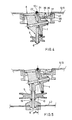
Fig. 2 is a sectional top plan view of a portion of a second embodiment taken along the line II-II of Fig. 3;
Fig. 3 is a sectional side view taken on the line III-III of Fig. 2;
Fig. 4 is sectional view of a portion of a fourth embodiment;
Fig. 5 is a view similar to Fig. 4 of a further embodiment of the invention;
Fig. 6 is a partly cutaway top plan view of a conveyor table according to the invention;
Fig. 7 shows a control grid for controlling a table with a conveyor unit according to Figs. 2 and 3; and
Fig. 8 shows a second embodiment of a control grid. - The portion of an embodiment of a conveyor table according to the invention shown in Fig. 1 is a conveyor unit supported by a support construction 9. The conveyor unit comprises a
conveyor member 1. Theconveyor member 1 has a rotation-symmetrical shape and is suspended relatively to the support construction 9 for rotation about itsaxis 2. - To that effect, the
conveyor member 1 is suspended for rotation about itsaxis 2 in asuspension member 8 which in turn is suspended for rotation about thesecond line 10 relatively to the support construction 9. Acircumferential portion 3 of theconveyor member 1, together with similar circumferential portions offurther conveyor members 1 constituting the conveyor table, defines a plane oftransport 4. The direction of transport of theconveyor member 1 can be adjusted by turning thatconveyor member 1 relatively to the support construction 9 about asecond line 10 perpendicular to the plane oftransport 4. Arranged parallel to the plane oftransport 4 is aguard 13 having substantiallycircular openings 14, one of which is shown in cross-section in Fig. 1. Theconveyor member 1 extends through theopenings 14 and is arranged relatively to theopening 14 in such a way that the correspondingsecond line 10 extends through the centre of that opening 14. - In virtue of the fact that the transport table is provided with a
guard 13, an article that is being conveyed over that table and will tilt for lack of support byconveyor members 1, can be taken up by theguard 13 and can be displaced glidingly over theguard 13 by theconveyor members 1 which that article is in contact with, until that article reaches one of anyfurther conveyor members 1 or is removed from the table. - For the control of the orientation of the
conveyor member 1 about thesecond line 10, thesuspension member 8 is provided with acontrol arm 11, to which a control rod or a control grid (see Figs. 7 and 8) can be connected for driving the rotation of theconveyor member 1 about the line perpendicular to the plane of thetransport 4. - The
guard 13 moreover keeps the control means which connect to thecontrol arm 11 and the greater part of the conveyor units out of the reach of the user of the table and protects these units against contamination. - In the table according to the invention the
conveyor members 1 extend above theguard 13 only by a minor distance, so that the surface of theguard 13 is easy to clean. - In virtue of the fact that the
openings 14 are circular and the correspondingsecond line 10 of each of thoseconveyor members 1 in each case intersects the centre of thecorresponding opening 14, eachconveyor member 1 extending through one of thoseopenings 14 be turned relatively to theguard 13 about thesecond line 10 corresponding with thatmember 1 without that member engaging or abutting against the edge of thecorresponding opening 14. - By means of friction transmission, the
conveyor member 1 is coupled to a rotation-symmetrical transmission member 5 which is rotatable about itsaxis 6. Thisaxis 6 is perpendicular to the plane oftransport 4. According to the embodiment shown, thetransmission member 5 is provided with acontinuous groove 7 for cooperation with a driving rope (see Fig. 6). For the sake of clarity, the driving ropes are not shown in Figs. 1-5. Naturally, for driving the transmission members, other means can be used instead of a driving rope, such as a chain, a geared belt, a toothed wheel or a worm. - Owing to the fact that the
axis 6 of thetransmission member 5 is perpendicular to the plane oftransport 4, the position of the plane in which thetransmission member 5 can rotate is oriented parallel to the plane oftransport 4, so that the rope may be provided in any desired directions parallel to the plane oftransport 4. This gives a great measure of freedom as to the arrangement of the power source, which can be arranged in any desired location in directions parallel to the plane oftransport 4. The mutual coupling oftransmission members 5 is also easy, irrespective of their mutual arrangement in directions parallel to the plane oftransport 4. - The
second line 10 and theaxis 6 of thetransmission member 5 are coaxial. As a result, the position of thetransmission member 5 relative to the support construction remains unchanged, irrespective of the orientation of the axis ofrotation 2 of theconveyor member 1. - The
conveyor member 1 has acircumferential portion 12 which during rotation of thatconveyor member 1 about itsaxis 2 extends through thecorresponding opening 14. Thiscircumferential portion 12 is constructed as a part of a sphere extending about thataxis 2, which sphere seals thecorresponding opening 14 except for an annular outer portion thereof. - Accordingly, the
spherical portion 12 of theconveyor member 1 partly extends continuously through thecorresponding opening 14. The annular gap is maintained irrespective of the orientation of theaxis 2 of theconveyor member 1. - An advantage of this embodiment of the invention is that an article that is slid into contact with the
conveyor member 1 in a direction transverse to the direction of transport of the member, is guided along thecircumferential portion 12 of thatconveyor member 1 towards thecircumferential portion 3 thereof, which co-defines the plane oftransport 4 and will further convey the article. - The opening 14 is virtually closed, so that any articles, parts of the body of persons within reach of the table and dirt will rarely be in a position to pass between the
conveyor member 1 and theguard 13 or be caught between them. - The
circumferential portion 3 referred to is coated with a layer ofrubber 22. This rough material prevents the occurrence of slip between the articles and theconveyor member 1 when articles are being conveyed at high speeds. - The
transmission member 5 comprises abevel gear 15, adriving wheel 17 in which thegroove 7 for receiving the driving rope (not shown) is provided and ashaft 16 which connects thewheels suspension member 8 has a U-shapedfork 18 in which theconveyor member 1 is suspended and within which thebevel gear 15 is suspended. Theshaft 16 extends from thebevel gear 15 mounted thereon, through the bottom of the U-shapedfork 18 of thesuspension member 8 under and through the support construction 9 to thedriving wheel 17. - The
bevel gear 15 engages with theconveyor member 1 by means of a frictional force which is exerted on arubber ring 19 provided about theconveyor member 1. Theshaft 16 is bearing-mounted relatively to the support construction 9 in a bearing bushing 20 which is suspended in asupport tube 21 which in turn is clamped in the support construction 9. Thesuspension member 8 is bearing-mounted on the outer surface of thatsupport tube 21. - Any forces exerted on the
conveyor member 1 are taken up by the U-shapedfork 18 of thesuspension member 8. Thebevel gear 15 is retained against theconveyor member 1 by means of aBelleville washer 23 for generating a normal force for the purpose of exerting the above mentioned frictional force on thering 19. - According to another preferred embodiment of the invention at least one of the conveyor members is suspended in a suspension member, characterized in that said suspension member is provided with an opening which said conveyor member extends through, said suspension member being substantially circular in section in the plane of the guard and filling up the corresponding opening, except for an annular outer portion thereof, that is.
- In the embodiment shown in Figs. 2 and 3, the
suspension member 8 is of C-shaped construction, leaving one end face of the conveyor element free. Thetransmission member 5 is provided with anannular flange 25 which extends around thesuspension member 8 and afree edge 27 of which engages arubber ring 19 arranged around theconveyor member 1 in the area of the free end face. The C-shapedsuspension member 8 forms an arc which extends about acontinuous flange 28 of theconveyor member 1. Thisflange 28 comprises the sphericalcircumferential portion 12 and thecircumferential part 3, which co-defines the plane oftransport 4. Within theflange 28radial ribs 29 extend to acylindrical portion 30 which is bearing-mounted on ashaft 31 and is arranged coaxially with theaxis 2 of theconveyor member 1. Theshaft 31 is further mounted in abore 32 in thesuspension member 8 and transmits forces which are exerted on theconveyor member 1 to thesuspension member 8. - The
suspension member 8 is bearing-mounted on the free end of apin 26 projecting from the support construction 9. Pressure forces on theconveyor member 1 are transmitted via thesuspension member 8 to the end of thepin 26. - Further, between the
suspension member 8 and the support construction 9 thetransmission member 5 is bearing-mounted on thepin 26. By means of aBelleville washer 33, thistransmission member 5 is pressed against therubber ring 19 mounted on theconveyor member 1, with a clearance being maintained between thetransmission member 5 and thesuspension member 8. - In addition to a
first groove 7, a second groove 7' is provided in thetransmission member 5. One of the grooves can receive a rope which drives the transmission member, while the other of the twogrooves 7 and 7' can receive a further rope which is intended for driving a transmission member of another conveyor unit. - At its free end, the
control arm 11 of thesuspension member 8 is connected to acontrol grid 60 for hinging movement. The control grid hasopenings 61, Fig. 3 showing one of them. Thesuspension member 8 can be turned by displacing thecontrol grid 60 translatingly along a circular path which is selected such that the point of thecontrol grid 60 through which extends the shaft of the hinge connection with thecontrol arm 11, is maintained at a constant distance b from thesecond line 10. - An advantage of such a control is that an accurate, low-clearance and wear-resistant control and hence an accurate mutual alignment of the
conveyor members 1 can be accomplished. The mutual distance between the conveyor units which is necessary to allow thecontrol grid 60 extending between them sufficient freedom of movement, can be maintained in the conveyor table according to the invention in virtue of the fact that theguard plate 13 takes care of a guidance of the articles between theconveyor members 1. - Fig. 7 shows a control grid suitable for combination with a conveyor unit according to Figs. 2 and 3. In one of the openings 61 a conveyor unit is shown. In addition to the
openings 61, the control grid has a plurality ofrecesses holes 65. In mounted position, in similar manner as in the case of the conveyor unit shown, acontrol arm 11 of a conveyor unit is connected to each of theholes 65. The thin chain-dotted lines represent the conveyor unit in a position where it has been turned through an angle of 180° about thesecond line 10. The corresponding position of thecontrol grid 60 is also indicated by thin chain-dotted lines. For turning the conveyor unit between the two positions indicated, the control grid is displaced translatingly along a portion of a circular path indicated byarrows 66. The drive of the displacement can be effected by means of a pin which engages ahole 67. It is also possible, however, to drive the rotation about the second line of one of theconveyor members 1, with theother conveyor members 1 being moved along by the correspondingcontrol arms 11 and thecontrol grid 60. It is observed that in order to create the possibility of transport in all directions of the plane of transport it is sufficient to provide for eachconveyor member 1 to be rotatable through 180° about itssecond line 10 and for reversibility of the direction of rotation of eachconveyor member 1 about itsaxis 2. - Fig. 8 shows a further example of a
control grid 60 withopenings 61, recesses 62, 63, and 64, and mountingholes 65. Such acontrol grid 60 is for instance suitable for use in a conveyor table according to Fig. 6 and with conveyor units in which the control arm extends along theaxis 2. In one of the openings 61 a conveyor unit is schematically represented in two positions where it has been pivoted relatively to thecontrol grid 60. It is observed that when mounted, the control grid moves about thesecond line 10 of each conveyor member, as described hereinabove. - The grid may also be connected to the free ends of each of the control arms by means of pin-slot connection, instead of a hinge joint. In that case a rectilinear translating displacement of the control grid can be converted into rotation of the conveyor members about the corresponding second lines.
- In the conveyor units shown in Figs. 4 and 5, each of the conveyor members is suspended in a
suspension member 8 and provided with anopening 34 which thecorresponding conveyor member 1 extends through. Thesuspension member 8 comprises a guarding portion 35 which is circular in section in the plane of theguard 13 and fills up thecorresponding opening 36. - During rotation of the
conveyor member 1 about thesecond line 10, the guarding portion 35 ofsuspension member 8 rotates along with it about thatsame line 10 and thus a closely fitting guard can be obtained irrespective of the form and the position of theconveyor member 1. In virtue thereof, theconveyor member 1 may be of light construction and inexpensive to manufacture, without a large passage arising between thatconveyor member 1 and the circumference of theopening 36. At the same time, this gives greater freedom as to the construction of the surface between the edge of theopening 36 and the portion of theconveyor member 1 that, at least partly, defines the plane oftransport 4. This surface may for instance be chosen such that articles sliding over theguard 13 in a direction transverse to the direction of transport of aconveyor member 1 are fluently guided to the portion of theconveyor member 1 which, at least partly, defines the plane oftransport 4. - A further advantage of this embodiment is that the
guard 13 can also be used, along with other means, to support thesuspension member 8. This option has been used in this embodiment in that theguard 13 also forms the support construction 9 and thesuspension member 8 is suspended in thecorresponding opening 36 in theguard 13. In this way a simple cost-reducing construction of the conveyor table according to the invention can be accomplished. A further advantage is the option of arranging a control grid under thetransmission members 5. This renders superfluous the necessity of providing sufficient freedom of movement for the control grid between the conveyor units, so that they can be arranged at a smaller mutual distance. Moreover, when thecontrol arms 11 are also arranged under thetransmission members 5, displacement of the control grid along a full circle can be obtained. - It is observed that when the
suspension member 8 is not constructed in such a way that it receives support from theguard 13, between the edge of eachopening 36 and thecorresponding suspension member 8 an annular gap can be left open to enable low-friction rotation of thesuspension member 8. - By means of a screw 39 a retaining
member 38 is mounted on the bottom of the suspension member. The retainingmember 8 comprises a continuousupright ridge 40, which extends into the vicinity of the combined support construction-guard plate 9, 13. - The direction of transport of the
conveyor member 1 can be changed by rotating thesuspension member 8 in theopening 36 in which it is bearing-mounted in therecess 37. In respect of this rotation option it is important there is some clearance between the retainingmember 38 and the bottom of the combined support construction-guard plate 9, 13. - The
suspension member 8 is provided with acontinuous ring groove 41 which is coaxial with theopening 36 to be engaged by a rope for driving the rotation of the conveyor member about thesecond line 10. - In the conveyor unit according to Fig. 4 the
transmission member 5 is suspended from thesuspension member 8 in such a way that the axis ofrotation 6 of thetransmission member 5 is coaxial with thesecond line 10, about which line theconveyor member 1 can rotate via thesuspension member 8 bearing-mounted in therecess 37. Thus the position of thetransmission member 5 relative to the support construction 9 remains unchanged when the direction of transport of theconveyor member 1 is changed. - In the conveyor table according to Fig. 5, the
second line 10 of each of theconveyor members 1 is disposed at a distance a from the corresponding axis ofrotation 6 of thetransmission member 5. At its end remote from thesuspension member 8, theshaft 16 of each of thetransmission members 5 is rotatably connected at a fixed place with acontrol grid 42. The control grid can be translatingly displaced relatively to the support construction 9 along a circular path having a radius equaling the distance a between thesecond line 10 and the axis ofrotation 6 of thetransmission member 5. - In this embodiment of the invention, too, a displacement of the control grid along a full circle can be provided. A further advantage of this embodiment is the simple construction due to the fact that the control arm is integrated into the
suspension member 8 and theshaft 16 of thetransmission member 5 also forms a pin for the pivoting connection between thesuspension member 8 and thecontrol grid 42. - Preferably, a further transmission member (not shown) is provided at a fixed place on the
control grid 42, which transmission member may be connected to a power source or a transmission member suspended from the support construction and whose position in axial direction corresponds to that of the saidtransmission member 5 of at least one of the conveyor units. One advantage of this is that upon rotation of theconveyor member 1 about thesecond line 10, the position of the saidtransmission member 5 of one of the conveyor units relative to the further transmission member remains unchanged and hence no special measures are necessary to maintain the mutual engagement of these transmission members. - Fig. 6 shows one example of a conveyor table in which twelve units 43 according to Fig. 4, each comprising a
conveyor member 1, are combined. - Connecting to the conveyor table are a supply track 47 as well as three discharge tracks 48, 49, 50. when the
conveyor members 1 are in the position shown when an article reaches the conveyor table, that article will be conveyed to the discharge track 49 diametrically opposite the supply track 47. For an article to be conveyed to the left-hand or right-hand discharge track 48 or 50, theconveyor members 1 can be rotated about the respectivesecond lines 10 thereof (see Fig. 4) counter-clockwise and clockwise, respectively, while the article is disposed on the conveyor table. - A first rope 44 for driving the rotation of the
conveyor members 1 about therespective axes 2 thereof, is in engagement with the transmission members 5a-5n, with a first driving wheel 45 which is directly connected to a power source 46 and a first bend wheel 51. A second rope 55 for driving the rotation of theconveyor members 1 about the respectivesecond lines 10 is in engagement withgrooves 41 in thesuspension members 8, whichgrooves 41 are each coaxial with theopening 36, a second bend wheel 52 and a second driving wheel 53. The second rope is trained on thesuspension members 8, the second bend wheel 52 and the second driving wheel 53 in the same way as the first rope 44 is trained on the transmission members 5a-5n, the first bend wheel 51, and the first driving wheel 45. - The ropes 44 and 55 may for instance be belts toothed on opposite sides or chains. According to the embodiment shown, the ropes are provided with stops 56 which are arranged in succession on a supporting rope at a mutually uniform distance. Provided in the transmission members 5a-5n, the
suspension members 8 and the wheels 45, 51, 52, and 53, are openings (not shown) which are adjusted for receiving the stops 56 as to their size and mutual interspace. The transmission of the force of the ropes by means of the stops 56 offers the advantage that no mutual differences in rate of circulation will occur between the transmission members 5a-5n and between thesuspension members 8 as a result of stretch of the rope. - The course of the ropes will now be described with reference to rope 44. It will be clear that by analogy the description also applies to the rope 55, which has a similar course. The rope is trained on the transmission members 5a-5n in such a way that they are all driven in one and the same direction. Accordingly, in each of the units 43, the influence of the rotation of the
conveyor member 1 about thesecond line 10 on the rate of rotation of theconveyor member 1 about itsaxis 2 is substantially the same. This is particularly advantageous in conjunction with the increased accuracy of the mutual alignment of the orientations of theconveyor members 1 as obtained by the use of a control grid. The direction of transport of the articles conveyed over the table can be changed during transport without the articles being turned. Due to turning, the articles might be transferred to one of the discharge tracks in an oblique position, which might cause that article to become stuck against a side ridge of that track. - The course of the rope 44 shows intersections of a portion that is located between the transition members 5a and 5b and a portion that is located between the transmission members 5e and 5h, as well as of a portion that is located between the transmission members 5i and 5j and a portion that is located between the transmission members 5m and 5n. At the intersection, the intersecting portions of the rope 44 are preferably disposed at different levels so that contact between them is avoided. This can be readily accomplished in the course of the rope 44 as shown, in virtue of the fact that portions of the rope 44 which are located between intersecting portions of that rope 44 pass along four
transmission members 5. The difference in level between the intersecting portions of the rope 44 can be achieved by providing the continuous grooves of the transmission members 5a-5h and 5i-5n, respectively, in a stepwise staggered relationship relative to each other. Relatively to a plane parallel to the plane oftransport 4, for instance, the groove of the transmission member 5a could be disposed at a level 0, while the grooves of the transmission members 5b-5h are located at levels disposed 1, 2, 3, 4, and 5 mm, respectively, above said plane. In this way a 1 mm difference between the respective levels of the successive transmission members 5a-5h yields a difference in height of more than 4.5 mm between the intersecting portions of the rope 44 at the intersection. The grooves of the transmission members 5i-5n may for instance be provided at 5, 4, 3, 2, 1 and 0 mm above said plane, so that between the intersecting portions of the rope 44 between the transmission members 5i and 5j and between the transmission members 5m and 5n, too, a difference in height of more than 4.5 mm is present and the continuous groove of the transmission member 5n will be disposed at the same level as the continuous groove of the transmission member 5a. - A further advantage of the invention is that the
guard 13 affords the option of sucking off air through theopenings conveyor members 1, so that an increased pressure force against the conveyor members is accomplished, particularly in the case of light, flexible articles, such as sheets of paper, so that they can be conveyed over the conveyor table at relatively high speeds, accurately, and with little or no slip, and blowing up of these articles is prevented. Due to the fact that air is sucked off only along the conveyor members, these articles are sucked against theguard 13 in the area between theconveyor members 1 to a limited extent only and the friction between the guard and the articles remains small. - Sucking off air along the
conveyor members 1 can easily be accomplished by providing the conveyor table with means for creating a reduced pressure under theguard 13. - In the conveyor members according to Figs. 1-3, the axes of
rotation 2 are oriented parallel to theguard 13. This offers the advantage that it enables an accurate unrolling movement of theconveyor member 1 relative to an article to be transported over it. This is particularly advantageous in conjunction with the improved mutual alignment, which can be obtained by using acontrol grid - The surface of the
guard 13 proximal to the plane oftransport 4 is preferably made of smooth material, such as PTFE, PA or anodized aluminium, so that a minimal friction between articles guided along theguard 13 and theguard 13 itself is obtained. - Further, to reduce friction between articles guided along the
guard 13 and theguard 13 itself, the surface of theguard 13 proximal to the plane oftransport 4 comprises material for dissipating static electricity.
Claims (15)
- A conveyor table for displacing along a transporting surface (4) articles with at least one substantially flat side, said table being provided with a support construction (9) and with a plurality of substantially rotation-symmetrical conveyor members (1) each suspended for rotation about an axis thereof relative to the support construction and circumferential portions thereof defining the plane of transport (4), the direction of transport of said conveyor member (1) being controllable by turning said transport member (1) relatively to said support construction about a second line (10), which is perpendicular to the plane of transport (4), characterized in that parallel to the plane of transport (4) a guard (13) is arranged having substantially circular openings (14, 36), at least a number of said openings (14, 36) each having one of said conveyor members (1) extending through them and each of said conveyor members (1) having its corresponding second line (10) extending virtually through the centre of the corresponding opening (14, 36).
- A conveyor table according to claim 1, characterized in that of at least one of the conveyor members (1), a circumferential portion (12) which during rotation of said conveyor member (1) about its axis (2) extends through the corresponding opening (14) is constructed as a portion of a sphere extending round about said axis, said sphere sealing off the corresponding opening (14) except for an annular outer portion thereof.
- A conveyor table according to claim 1, in which at least one of the conveyor members (1) is suspended in a suspension member (8), characterized in that said suspension member (8) is provided with an opening (34), which said conveyor member (1) extends through, said suspension member (8) being substantially circular in section in the plane of the guard (13) and filling up the corresponding opening (36), at least, except for an annular outer portion thereof.
- A conveyor table according to claim 3, characterized in that the guard (13) also forms the support construction (9) and at least said suspension member (8) is suspended in the corresponding opening (36) in the guard (13).
- A conveyor table according to claim 4, characterized in that the second line (10) of each of the conveyor members (1) is located at a distance (a) from the corresponding axis of rotation (6) of the transmission member, the shaft (16) of each of the transmission members (5) having its end remote from the suspension member (8) rotatably connected at a fixed place with a control grid (42), which is adapted for translating displacement relative to the support construction (9) along a circular path having a radius equal to the distance (a) between the second line (10) and the axis of rotation (6) of the transmission member (5).
- A conveyor table according to claim 1, characterized by means for sucking off air along the conveyor members (1).
- A conveyor table according to claim 6, characterized by means for creating a reduced pressure under the guard (13).
- A conveyor table according to claim 1, characterized in that each of the conveyor members (1) is suspended from a suspension member (8), each of the suspension members (8) being suspended for rotation about the corresponding second axis (10) relatively to the support construction (9) and being provided with a control arm (11), the control arms (11) being mutually connected by means of a control grid (60) which is connected to a free end of each of the control arms (11) for hinge movement, each control arm (11) being connected to the control grid (60) in such a way that the conveyor members (1) are always oriented for transport in a common direction.
- A conveyor table according to claim 8, characterized in that the control grid is suspended in a plane that extends through the conveyor members (1) and the suspension members (8) and is provided with openings (61) and recesses (62, 63, 64) each leaving space for one of the conveyor members (1) and a corresponding suspension member (8), and being formed in such a way that the control grid (60) can be translatingly displaced in its plane relatively to the second lines (10) of each of said conveyor members (1) along a part of a circular path having a radius equal to the distance (b) between each of the second lines (10) and the axis of the hinge at the free end of the corresponding control arm (11).
- A conveyor table according to claim 5 or 8, characterized in that the transmission members (5) are connected in such a way that they are drivable in one and the same direction of rotation by the at least one power source (46)
- A conveyor table according to claim 10, characterized by at least one group of six conveyor members (1), each coupled with a transmission member (5a-5h, 5i-5n), with a rope (44) engaging with said transmission members (5a-5h, 5i-5n), which are arranged in two parallel, opposite rows, each consisting of three of said transmission members (5a, 5e, 5d; 5h, 5b, 5c; 5i, 5m, 5l; 5n, 5j, 5k), the rope (44) being wound about a first outer and a central pair of opposite transmission members (5b, 5e and 5c, 5d; 5m, 5j and 5l, 5k) and extending obliquely from each of the central transmission members (5e, 5b, 5m, 5j) to a transmission member (5h, 5a, 5n, 5i, respectively) forming part of the other row and a second pair of exterior transmission members, said rope (44) passing between the transmission members (5a and 5h; 5i and 5n, respectively) of the second outer pair, the portions of the rope (44) extending between the central and the second outer pair of transmission members (5e, 5b and 5h and 5a; and 5m, 5j and 5i, 5n, respectively) intersecting each other and the transmission members (5a-5h; 5i-5n) succeeding each other along the course of rope (44) being arranged relatively to the plane of transport (4) in stepwise, vertically staggered relationship.
- A conveyor table according to claim 5 or 8, characterized in that the axes of rotation (2) of at least a number of the conveyor members are directed parallel to the guard (13).
- A conveyor table according to claim 1, characterized in that the surface of the guard (13) proximal to the plane of transport (4) is made of smooth material, such as PTFE, PA or anodized aluminium.
- A conveyor table according to claim 1, characterized in that the surface of the guard (13) proximal to the plane of transport (4) comprises material for dissipating static electricity.
- A unit for application in a conveyor table for displacing along a transporting surface articles having at least one substantially flat side, comprising a suspension member (8) and a substantially rotation-symmetrical conveyor member (1) suspended for rotation about its axis (2) from the suspension member (8), characterized in that the suspension member (8) is substantially circular in section in at least one plane parallel to and spaced away from said axis (2).
Priority Applications (1)
| Application Number | Priority Date | Filing Date | Title |
|---|---|---|---|
| EP94200778A EP0611012B1 (en) | 1989-12-14 | 1990-12-13 | Conveyor table |
Applications Claiming Priority (2)
| Application Number | Priority Date | Filing Date | Title |
|---|---|---|---|
| NL8903070 | 1989-12-14 | ||
| NL8903070A NL8903070A (en) | 1989-12-14 | 1989-12-14 | TRANSPORT TABLE. |
Related Child Applications (2)
| Application Number | Title | Priority Date | Filing Date |
|---|---|---|---|
| EP94200778A Division EP0611012B1 (en) | 1989-12-14 | 1990-12-13 | Conveyor table |
| EP94200778.2 Division-Into | 1990-12-13 |
Publications (2)
| Publication Number | Publication Date |
|---|---|
| EP0438820A1 true EP0438820A1 (en) | 1991-07-31 |
| EP0438820B1 EP0438820B1 (en) | 1995-10-04 |
Family
ID=19855783
Family Applications (2)
| Application Number | Title | Priority Date | Filing Date |
|---|---|---|---|
| EP90203284A Expired - Lifetime EP0438820B1 (en) | 1989-12-14 | 1990-12-13 | Conveyor table |
| EP94200778A Expired - Lifetime EP0611012B1 (en) | 1989-12-14 | 1990-12-13 | Conveyor table |
Family Applications After (1)
| Application Number | Title | Priority Date | Filing Date |
|---|---|---|---|
| EP94200778A Expired - Lifetime EP0611012B1 (en) | 1989-12-14 | 1990-12-13 | Conveyor table |
Country Status (4)
| Country | Link |
|---|---|
| US (1) | US5222585A (en) |
| EP (2) | EP0438820B1 (en) |
| DE (2) | DE69033367T2 (en) |
| NL (1) | NL8903070A (en) |
Cited By (3)
| Publication number | Priority date | Publication date | Assignee | Title |
|---|---|---|---|---|
| EP0564740B1 (en) * | 1992-04-09 | 1996-12-18 | GIDDINGS & LEWIS INC. | Rotate/translate conveyor module |
| WO1998033727A1 (en) * | 1997-01-29 | 1998-08-06 | Knapp Logistik Automation Gesellschaft Mbh | Points for a conveyor arrangement |
| EP3760557A4 (en) * | 2018-02-27 | 2021-11-24 | Itoh Denki Co., Ltd. | Conveyor device and conveying-direction changing device |
Families Citing this family (18)
| Publication number | Priority date | Publication date | Assignee | Title |
|---|---|---|---|---|
| IL117242A0 (en) | 1996-02-23 | 1996-06-18 | Orbotech Ltd | Conveyor system having selectively enabled conveyor elements |
| IL120071A (en) * | 1997-01-24 | 2002-03-10 | Orbotech Ltd | Method and system for continuously processing workpieces along a production line |
| DE29920618U1 (en) * | 1999-11-24 | 2000-02-24 | Holzma Maschinenbau Gmbh | Friction roller |
| JP3562635B2 (en) * | 2000-06-20 | 2004-09-08 | 伊東電機株式会社 | Transfer direction changing device |
| JP3516343B1 (en) * | 2002-06-20 | 2004-04-05 | 旭精機工業株式会社 | Transfer device and transfer system |
| DE20216094U1 (en) * | 2002-10-19 | 2003-05-08 | Transnorm System Gmbh | Conveyer roller powered by second roller with raised friction at right angles to first |
| US7040478B2 (en) * | 2003-08-05 | 2006-05-09 | Rapistan Systems Advertising Corp. | Steerable diverter system |
| US8292063B2 (en) * | 2007-02-25 | 2012-10-23 | Fori Automation, Inc. | Pallet conveyor with corner assembly |
| US7708134B2 (en) * | 2007-02-25 | 2010-05-04 | Fori Automation, Inc. | Power conveyor with corner assembly and pallet therefor |
| US20100065400A1 (en) * | 2008-09-09 | 2010-03-18 | David Pruett | Ball transfer device |
| JP5551888B2 (en) * | 2009-04-14 | 2014-07-16 | 株式会社井口機工製作所 | Free ball bearing, bearing device, support table, transfer equipment, turntable |
| AT510224A1 (en) | 2010-07-16 | 2012-02-15 | Tgw Mechanics Gmbh | TRANSFER CONVEYOR |
| JP6771864B2 (en) * | 2015-04-30 | 2020-10-21 | トーヨーカネツ株式会社 | Sorting device |
| US10464753B2 (en) | 2017-09-19 | 2019-11-05 | Omtec, Corp. | Pop-up wheel device for use in material handling equipment |
| DE102017125981A1 (en) * | 2017-11-07 | 2019-05-09 | Josef Moser | Ball feed table system |
| JP7383042B2 (en) * | 2019-03-22 | 2023-11-17 | フィブ・イントラロジスティクス・コーポレイション | Conveyor with anti-jam diverter wheel |
| KR102099107B1 (en) * | 2019-07-09 | 2020-04-09 | 화동하이테크 주식회사 | Diverter for Transferring Conveyor |
| CN112777192A (en) * | 2019-11-07 | 2021-05-11 | 伊东电机株式会社 | Conveying device and conveying direction changing device |
Citations (4)
| Publication number | Priority date | Publication date | Assignee | Title |
|---|---|---|---|---|
| US1460539A (en) * | 1919-05-08 | 1923-07-03 | William L Leary | Conveying apparatus |
| DE1931701A1 (en) * | 1969-06-23 | 1971-01-07 | Dahmen Kg Werkstaetten Karl | Device for transporting packaged or self-supporting goods |
| DE8629392U1 (en) * | 1986-11-04 | 1987-04-09 | Trumpf Gmbh & Co, 7257 Ditzingen, De | |
| EP0311699A1 (en) * | 1987-10-12 | 1989-04-19 | Carl Schenck Ag | Transport device for turning round piece-goods on the same level |
Family Cites Families (21)
| Publication number | Priority date | Publication date | Assignee | Title |
|---|---|---|---|---|
| US1660327A (en) * | 1926-06-09 | 1928-02-28 | Pittsburgh Plate Glass Co | Cutting table |
| DE1237003B (en) * | 1963-09-14 | 1967-03-16 | Martin Roeckner Dipl Ing | Ball table for roller conveyors or the like. |
| GB1240077A (en) * | 1968-11-22 | 1971-07-21 | Bernard Kuzniak | Improvements relating to pneumatic conveyors |
| US3739894A (en) * | 1971-03-15 | 1973-06-19 | Western Gear Corp | Ball transfer unit |
| DE2117546A1 (en) * | 1971-04-10 | 1972-10-19 | Mertens H | All-round rolling table |
| BE793824A (en) * | 1972-01-11 | 1973-07-10 | Wagner Ab Fredr | SWITCHING MECHANISM FOR CARRIERS |
| GB1366206A (en) * | 1972-07-07 | 1974-09-11 | Sovex Ltd | Diverting arrangements for example in conveying devices |
| US3920290A (en) * | 1974-02-11 | 1975-11-18 | J & M Hydraulic Servic Inc | Ball transfer unit |
| US3978975A (en) * | 1975-06-30 | 1976-09-07 | The Boeing Company | Cargo power drive unit |
| US4180150A (en) * | 1977-10-27 | 1979-12-25 | Moore Archie S | Multi-directional transfer device |
| US4399675A (en) * | 1981-10-29 | 1983-08-23 | The Boeing Company | Apparatus and method for sheet metal part alignment |
| US4696583A (en) * | 1984-05-25 | 1987-09-29 | The Boeing Company | Ball support assembly |
| US4706793A (en) * | 1985-07-15 | 1987-11-17 | Camillo Masciarelli | Conveyor system with rollers and plungers |
| JPS6256202A (en) * | 1985-09-02 | 1987-03-11 | Isao Kurata | Transport mechanism |
| US4660994A (en) * | 1986-04-23 | 1987-04-28 | Camillo Masciarelli | Anti-friction element |
| US4732490A (en) * | 1986-04-23 | 1988-03-22 | Camillo Masciarelli | Anti-friction element |
| DE3637003C1 (en) * | 1986-10-30 | 1988-02-04 | Loedige Foerdertechnik | Transport deck for piece goods or the like |
| NL8700099A (en) * | 1987-01-16 | 1988-08-16 | Nico Rombouts | TRANSPORTATION DEVICE WITH POWERED BALLS, PROTECTIVE FROM OVERLOADING. |
| GB8801911D0 (en) * | 1988-01-28 | 1988-02-24 | Weldwork Cargo Systems Ltd | Rolling ball assembly for rolling ball deck |
| DE3805494A1 (en) * | 1988-02-22 | 1989-08-31 | Bavaria Cargo Tech | CONVEYOR BALL UNIT |
| US5012914A (en) * | 1989-10-23 | 1991-05-07 | Automotion, Inc. | Diverter assembly for article conveyor |
-
1989
- 1989-12-14 NL NL8903070A patent/NL8903070A/en not_active Application Discontinuation
-
1990
- 1990-12-13 DE DE69033367T patent/DE69033367T2/en not_active Expired - Fee Related
- 1990-12-13 DE DE69022840T patent/DE69022840T2/en not_active Expired - Fee Related
- 1990-12-13 EP EP90203284A patent/EP0438820B1/en not_active Expired - Lifetime
- 1990-12-13 EP EP94200778A patent/EP0611012B1/en not_active Expired - Lifetime
- 1990-12-14 US US07/627,508 patent/US5222585A/en not_active Expired - Lifetime
Patent Citations (4)
| Publication number | Priority date | Publication date | Assignee | Title |
|---|---|---|---|---|
| US1460539A (en) * | 1919-05-08 | 1923-07-03 | William L Leary | Conveying apparatus |
| DE1931701A1 (en) * | 1969-06-23 | 1971-01-07 | Dahmen Kg Werkstaetten Karl | Device for transporting packaged or self-supporting goods |
| DE8629392U1 (en) * | 1986-11-04 | 1987-04-09 | Trumpf Gmbh & Co, 7257 Ditzingen, De | |
| EP0311699A1 (en) * | 1987-10-12 | 1989-04-19 | Carl Schenck Ag | Transport device for turning round piece-goods on the same level |
Cited By (5)
| Publication number | Priority date | Publication date | Assignee | Title |
|---|---|---|---|---|
| EP0564740B1 (en) * | 1992-04-09 | 1996-12-18 | GIDDINGS & LEWIS INC. | Rotate/translate conveyor module |
| WO1998033727A1 (en) * | 1997-01-29 | 1998-08-06 | Knapp Logistik Automation Gesellschaft Mbh | Points for a conveyor arrangement |
| AT406041B (en) * | 1997-01-29 | 2000-01-25 | Knapp Holding Gmbh | SWITCH FOR A CONVEYOR |
| US6179113B1 (en) | 1997-01-29 | 2001-01-30 | Knapp Logistik Automation Gellschaft M.B.H. | Points for a conveyor arrangement |
| EP3760557A4 (en) * | 2018-02-27 | 2021-11-24 | Itoh Denki Co., Ltd. | Conveyor device and conveying-direction changing device |
Also Published As
| Publication number | Publication date |
|---|---|
| NL8903070A (en) | 1991-07-01 |
| EP0611012B1 (en) | 1999-11-24 |
| DE69033367D1 (en) | 1999-12-30 |
| EP0438820B1 (en) | 1995-10-04 |
| US5222585A (en) | 1993-06-29 |
| DE69022840D1 (en) | 1995-11-09 |
| EP0611012A1 (en) | 1994-08-17 |
| DE69033367T2 (en) | 2000-06-08 |
| DE69022840T2 (en) | 1996-06-20 |
Similar Documents
| Publication | Publication Date | Title |
|---|---|---|
| EP0438820A1 (en) | Conveyor table | |
| KR101560018B1 (en) | Conveyor systems for diverting objects | |
| JP2902050B2 (en) | Product alignment equipment | |
| JP2895224B2 (en) | Modular transport device | |
| EP1075443B1 (en) | Transverse conveyance apparatus for roller conveyors and a lift device | |
| US4180150A (en) | Multi-directional transfer device | |
| WO1992004258A1 (en) | Side-flexing chain with wheels | |
| JPH11500399A (en) | Powered conveyor / belt converter | |
| CA2361894A1 (en) | Low tension dual helical conveyor system | |
| US4509636A (en) | Diverting roller system | |
| US4819787A (en) | Apparatus for transporting materials | |
| JPH01133805A (en) | Conveyor for turning bulk material in one plane | |
| JPWO2019167864A1 (en) | Transport device and transport direction changing device | |
| KR0134821B1 (en) | Rolling ball assembly and deck | |
| US4196312A (en) | Accumulation live roller conveyor | |
| JP7176726B2 (en) | Conveyor with rolling mechanism | |
| US3713555A (en) | Conveyor | |
| CN111410001A (en) | Liftable roller conveyor and conveying line convenient to pass through | |
| US4919256A (en) | Loading roller conveyor with drive via intermediate rollers | |
| JPH04367432A (en) | Direction regulating device for container | |
| CN220282430U (en) | Light-duty rotary conveying mechanism | |
| CN208630939U (en) | A kind of roller suitable for soft bag reason bag machine | |
| JPH06312832A (en) | Cross-feeder | |
| GB2152463A (en) | Powered overhead conveyor systems | |
| CN108860758A (en) | A kind of roller suitable for soft bag reason bag machine |
Legal Events
| Date | Code | Title | Description |
|---|---|---|---|
| PUAI | Public reference made under article 153(3) epc to a published international application that has entered the european phase |
Free format text: ORIGINAL CODE: 0009012 |
|
| 17P | Request for examination filed |
Effective date: 19901213 |
|
| AK | Designated contracting states |
Kind code of ref document: A1 Designated state(s): DE FR GB NL |
|
| 17Q | First examination report despatched |
Effective date: 19930402 |
|
| GRAA | (expected) grant |
Free format text: ORIGINAL CODE: 0009210 |
|
| AK | Designated contracting states |
Kind code of ref document: B1 Designated state(s): DE FR GB NL |
|
| XX | Miscellaneous (additional remarks) |
Free format text: TEILANMELDUNG 94200778.2 EINGEREICHT AM 13/12/90. |
|
| ET | Fr: translation filed | ||
| REF | Corresponds to: |
Ref document number: 69022840 Country of ref document: DE Date of ref document: 19951109 |
|
| PLBE | No opposition filed within time limit |
Free format text: ORIGINAL CODE: 0009261 |
|
| STAA | Information on the status of an ep patent application or granted ep patent |
Free format text: STATUS: NO OPPOSITION FILED WITHIN TIME LIMIT |
|
| 26N | No opposition filed | ||
| PGFP | Annual fee paid to national office [announced via postgrant information from national office to epo] |
Ref country code: NL Payment date: 19991223 Year of fee payment: 10 |
|
| NLT1 | Nl: modifications of names registered in virtue of documents presented to the patent office pursuant to art. 16 a, paragraph 1 |
Owner name: NEOPOST B.V. |
|
| PG25 | Lapsed in a contracting state [announced via postgrant information from national office to epo] |
Ref country code: NL Free format text: LAPSE BECAUSE OF NON-PAYMENT OF DUE FEES Effective date: 20010701 |
|
| NLV4 | Nl: lapsed or anulled due to non-payment of the annual fee |
Effective date: 20010701 |
|
| REG | Reference to a national code |
Ref country code: GB Ref legal event code: IF02 |
|
| PGFP | Annual fee paid to national office [announced via postgrant information from national office to epo] |
Ref country code: DE Payment date: 20051212 Year of fee payment: 16 |
|
| PGFP | Annual fee paid to national office [announced via postgrant information from national office to epo] |
Ref country code: FR Payment date: 20051219 Year of fee payment: 16 |
|
| PGFP | Annual fee paid to national office [announced via postgrant information from national office to epo] |
Ref country code: GB Payment date: 20051222 Year of fee payment: 16 |
|
| PG25 | Lapsed in a contracting state [announced via postgrant information from national office to epo] |
Ref country code: DE Free format text: LAPSE BECAUSE OF NON-PAYMENT OF DUE FEES Effective date: 20070703 |
|
| GBPC | Gb: european patent ceased through non-payment of renewal fee |
Effective date: 20061213 |
|
| REG | Reference to a national code |
Ref country code: FR Ref legal event code: ST Effective date: 20070831 |
|
| PG25 | Lapsed in a contracting state [announced via postgrant information from national office to epo] |
Ref country code: GB Free format text: LAPSE BECAUSE OF NON-PAYMENT OF DUE FEES Effective date: 20061213 |
|
| PG25 | Lapsed in a contracting state [announced via postgrant information from national office to epo] |
Ref country code: FR Free format text: LAPSE BECAUSE OF NON-PAYMENT OF DUE FEES Effective date: 20070102 |