EP0437655B1 - Châssis en échelle - Google Patents
Châssis en échelle Download PDFInfo
- Publication number
- EP0437655B1 EP0437655B1 EP90100914A EP90100914A EP0437655B1 EP 0437655 B1 EP0437655 B1 EP 0437655B1 EP 90100914 A EP90100914 A EP 90100914A EP 90100914 A EP90100914 A EP 90100914A EP 0437655 B1 EP0437655 B1 EP 0437655B1
- Authority
- EP
- European Patent Office
- Prior art keywords
- carriers
- longitudinal
- ladder frame
- frame according
- transverse
- Prior art date
- Legal status (The legal status is an assumption and is not a legal conclusion. Google has not performed a legal analysis and makes no representation as to the accuracy of the status listed.)
- Expired - Lifetime
Links
Images
Classifications
-
- B—PERFORMING OPERATIONS; TRANSPORTING
- B62—LAND VEHICLES FOR TRAVELLING OTHERWISE THAN ON RAILS
- B62D—MOTOR VEHICLES; TRAILERS
- B62D21/00—Understructures, i.e. chassis frame on which a vehicle body may be mounted
- B62D21/02—Understructures, i.e. chassis frame on which a vehicle body may be mounted comprising longitudinally or transversely arranged frame members
Definitions
- Such lead frames are each attached to the chassis frame of a truck or a trailer and serve to transmit the forces introduced into the floor covering profiles due to the load onto the chassis.
- Boards made of wood-based materials, wooden boards, metal profiles or sheet metal plates are usually used as floor covering profiles, each of which forms the so-called loading area with its upper side and which is supported on the lead frame with its lower side.
- Bodies are understood to mean both open and closed bodies, such as, for example, platform, tipping, box and refrigerated bodies.
- Platforms are to be understood as pure loading areas that have no laterally closing elements or the like. Have structures.
- Lead frames of the generic type i.e. those in which the side members have openings in the intersection area through which the cross members extend, result in a relatively torsion-resistant construction, in particular when the cross members are connected to one another at the respective intersection points in the region of the neutral zone.
- Torsionally soft leadframe constructions have the advantage that practically no cracking problems occur in the area of the connection points between the longitudinal and cross members, which is particularly advantageous in vehicles with long bodies or vehicles for off-road use. It is also advantageous that, due to the openings in the side members, the position of the cross members relative to the side members is precisely specified, so that only relatively simple devices can be used when mounting the cross members on the side members.
- lead frames of the generic type have the disadvantage that the contact surfaces of the cross members are always offset in height below the contact surfaces of the side members.
- compensating constructions must therefore be arranged on the contact surfaces of the crossbeams, as a result of which the construction and assembly become more complex and therefore more expensive, as a result of which the above Advantage in connection with the position of the cross members over the side members is largely nullified again.
- cross members are placed on the top of the longitudinal members and connected to them by means of stiffening or gusset plates.
- the contact surfaces of the crossmember lie in a common plane, so that there is a flush construction with respect to the crossmember, which does not require any construction-consuming compensating structures, since the floor covering profiles rest directly on the contact surfaces of the crossmember.
- connection with stiffening or gusset plates results in a relatively torsionally or torsionally rigid construction which leads to undesirable crack formation in vehicles for off-road use or in vehicles with long structures.
- sections of the side members running between adjacent cross members cannot be used to support the floor covering profiles, as a result of which the specific load capacity is adversely affected, particularly in the critical central region of the loading area. Due to the arrangement of the cross members on the top of the side members, such lead frames are also comparatively high, which also has an unfavorable effect on the loading area and vehicle height.
- US Pat. No. 4,534,589 describes a lead frame for supporting and fastening floor covering profiles with two parallel longitudinal beams and a large number of mutually parallel cross beams.
- This lead frame shows the features of the preamble of claim 1.
- the longitudinal members have notches on their upper side, into which the cross members, which are designed as a straight U-profile, are inserted from above.
- This construction is therefore not suitable for longitudinal beam profiles with an overhead belt that would offer a better contact surface as well as better load-bearing and deformation properties.
- a particularly rigid and torsionally rigid frame is realized, which, as described above, can lead to crack formation, in particular in vehicles with long bodies or in vehicles for off-road use.
- the US-PS 27 00 551 describes a chassis frame for trucks, which is constructed from two parallel side members and a plurality of parallel cross members, but does not belong to the aforementioned type of lead frames, which are attached as a subframe for attaching floor covering profiles on a chassis frame.
- the cross members have some deformations, such as offsets, and the longitudinal members are plugged onto straight end sections of the cross members and welded to them.
- the upper edges of the cross beams are arranged lower than the upper edges of the longitudinal beams.
- This known construction aims to create a frame that is as torsion and torsionally rigid as possible.
- the object of the present invention is to develop a lead frame of the type mentioned at the outset in such a way that, with a simple construction and simple assembly, a flush construction with an increased specific loading area load is achieved.
- a leadframe construction is created for the first time, which on the one hand combines the advantages of the known leadframe structures described at the outset and on the other hand avoids their disadvantages.
- leadframe constructions of the type according to the invention are relatively torsion-resistant, so that cracking problems do not occur. Due to the deformation of the cross members, the contact surfaces of the cross members lie in the plane of the contact surfaces of the side members, so that both the cross members and the side members can be used to support and fasten the floor covering profiles without the need for complex compensation structures. Also, no complex devices are required during assembly so that the position of the cross members on the longitudinal members is precisely fixed by the openings arranged in the longitudinal members. Measurement errors during assembly can therefore not occur.
- the construction Due to the bearing surfaces of all beams lying on one level, the construction is absolutely flush with the floor covering profiles with a high specific load-bearing capacity, which also means that heavy loads can be loaded Device, such as forklifts, is possible. Furthermore, stiffening or gusset plates for connecting the cross members to the side members are not required. The welding effort for connecting the cross members to the side members is comparatively low, as is the case with lead frame constructions of the generic type.
- the cross members are inserted through the openings in the longitudinal members until they have reached their final position.
- this type of assembly can only be realized if the cross members are continuously straight.
- the merit of the inventor can be seen in particular in recognizing that deformed cross members can also be inserted through the openings in the side members, provided the deformation of the cross members is coordinated with the shape of the openings in the side members.
- the deformation of the cross member can be designed in a variety of ways.
- the deformation of the crossbeams in the intersection area can be designed as an offset.
- Such an offset is preferably achieved by bending out a cross member section of a certain length laterally offset with respect to the longitudinal axis of the cross member.
- This offset formed by laterally bending out a cross member section can be designed in a variety of ways. So it is possible to make the overhang arc-shaped or V-shaped. However, it is particularly advantageous to make the overhang trapezoidal. On the one hand, this makes it easy to insert the Installation enables and on the other hand ensures that the largest possible contact surface of the cross member is available to support the floor covering profiles.
- a particularly useful trapezoidal configuration is achieved in that the offset cross member section is aligned parallel to the laterally adjacent, usually straight sections of the cross member and has adjoining transition sections on both sides at an obtuse angle, which merge into the laterally adjacent sections.
- the arrangement is preferably such that the transition sections run at an angle of approximately 150 ° to the parallel offset cross member section.
- Lead frames are assembled from commercially available profiles for cost reasons.
- U-profiles, Z, double-T or C-profiles are used for the side members as well as for the cross members. If such profiles are used, it is advantageous to adapt the openings in the longitudinal beams to the profile shape and to arrange them in the region of the web between the upper and lower flange of the profiles.
- top flange and the bottom flange of the respective cross member run essentially parallel to one another in the region of the offset.
- the longitudinal beams of a lead frame do not run straight through, but laterally with respect to the longitudinal direction have offset sections.
- Such longitudinal beams which are laterally offset in the longitudinal direction can also be provided in the case of lead frames designed according to the invention.
- connection of the side members with the cross members can basically be done in any way. It is advantageous to design the connection as a welded connection with a vertically extending weld seam. In order to ensure the torsionally soft construction described at the outset, it is expedient to connect the cross members in the region of the neutral zone to the longitudinal members.
- the connection in the area of the neutral zone means that crack formation is practically impossible, especially when using welded connections.
- the side members generally have a greater profile height than the cross members
- the cross members will have a deformation in the form of an overhang.
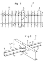
- the lead frame 10 consists of two side members 14 and a number of cross members 16 running transversely to the side members 14.
- the longitudinal members 14 each consist of a straight section in which they run parallel to one another, an angled section adjoining this straight section at an obtuse angle, in which they diverge, and a further straight section adjoining the angled section, in which they are arranged in one run larger distance than in the first straight section parallel to each other.
- This side member design represents one of many design options. Basically, the shape of the side member of the truck chassis is always decisive.
- the cross beams are arranged next to one another and approximately parallel to one another at approximately equal distances. They are each connected to the longitudinal beams 14 in the intersection area 12, as will be described in the following.
- a complete leadframe naturally also has a large number of further elements, which are omitted in the present FIG. 1 for the sake of clarity.
- FIG. 2 shows the construction of the lead frame according to the invention in the intersection area 12 between the longitudinal beam 14 and the cross beam 16.
- the longitudinal beam 14 and the cross beam 16 are formed by a commercially available, horizontally arranged U-profile.
- the upper leg of the U-profile forms the upper chord and the lower leg forms the lower chord of the construction.
- the web running between the legs has a greater height in the case of the longitudinal member 14 than in the case of the cross member 16.
- the longitudinal beam 14 is provided with an opening 18 in the intersection area 12.
- this opening 18 corresponds approximately to the cross section of the cross member 16. In the present exemplary embodiment, it is arranged only in the web of the side member somewhat below the top chord.
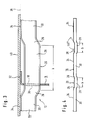
- the upper side of the upper chord forms a support surface 32 and 34 for a floor covering profile 40 both in the longitudinal beam 14 and in the cross beam 16, as shown in FIG. 3.
- the floor covering profile 40 is designed as a plate.
- each cross member 16 is deformed in the intersection area 12 such that the contact surface 34 of the cross member 16 lies in a common plane 38 (see FIG. 3) with the contact surface 32 of the side member 14.
- this deformation is designed as a trapezoidal offset 20.
- This trapezoidal offset 20 has an offset cross member section 28 which runs parallel to the laterally adjacent sections 30 of the cross member. Transition sections 26 adjoin the offset cross member section 28 on both sides at an obtuse angle and merge into the laterally adjacent sections 30.
- Such a trapezoidal offset can be produced relatively easily in a simple bending device.
- the deformation of the cross member 16 in the manner of an offset 20 is according to the invention matched to the cross section of the opening 18 in the cross member 14 such that the cross member 16 can be inserted through the opening 18 into the final position shown in FIGS. 2 and 3.
- This final situation lies the Support surface 32 of side member 14 and support surface 34 of cross member 16 in support plane 38 for floor covering profiles 40.
- the cross members 16 are connected to the longitudinal members 14 by means of a vertically running weld seam 36, as is shown in FIGS. 2 and 3.
- each cross member 16 has two offsets 20, as shown in FIG. 4.
- the length b of the offset section 28 of the offset 20 is chosen to be somewhat greater than the length d of the offset of each longitudinal member 14 (cf. FIG. 1). This ensures that all cross members 16 of the lead frame according to the invention can be of the same design and can be arranged both in the first straight section, in the diverging angled section and in the further straight section of the side members 14.
- the lead frame 10 To assemble the lead frame 10 according to the invention, it is only necessary to arrange the two longitudinal beams next to one another in a mounting device at the predetermined distance and in the predetermined orientation. Subsequently, only the cross member 16 must be inserted through the openings 18 in their final position. Due to the absolutely identical design of the cross member 16, mix-ups or incorrect arrangements are not possible. Also, with regard to the spacing of the cross members and the position relative to the side members, no errors can be made, since these parameters are exactly predetermined by the openings 18 provided in the side members. It is only necessary to provide means to prevent the cross members 16 from closing inserted too far or too little. This can be done, for example, by simple stops in the area of the cross beam ends.
Landscapes
- Engineering & Computer Science (AREA)
- Chemical & Material Sciences (AREA)
- Combustion & Propulsion (AREA)
- Transportation (AREA)
- Mechanical Engineering (AREA)
- Body Structure For Vehicles (AREA)
- Lead Frames For Integrated Circuits (AREA)
- Piezo-Electric Or Mechanical Vibrators, Or Delay Or Filter Circuits (AREA)
- Ladders (AREA)
Claims (15)
- Châssis en échelle (10), pour soutenir et fixer des profilés de revêtement de plancher (40) venant de structures ou de plates-formes de camions ou de remorques,- avec un ou plusieurs longerons (14)- une pluralité de traverses (16), s'étendant transversalement par rapport aux longerons et leur étant reliées,- avec des passages (18) fermés en pourtour, ménagés dans les longerons (14) et à travers lesquels s'étendent les traverses (16),- avec des surfaces d'appui (32), réalisées en face supérieure des longerons (14) et sur lesquelles reposent les profilés de garniture de plancher (40),- ainsi qu'avec des surfaces d'appui (34), réalisées en face supérieure des traverses (16),caractérisé en ce que- dans la zone de croisement (12) avec les longerons (14), les traverses (16) sont déformées de façon que les surfaces d'appui (34) des traverses (16) soient situées dans le plan (38) des surfaces d'appui (32) des longerons (14),- et en ce que la déformation des traverses (16) et les passages (18), fermés en pourtour et ménagés dans le longeron (14), sont conçus, les uns pur rapport aux autres, de manière que les traverses (16) puissent être enfilées, conjointement avec les tronçons (20) déformés, à travers les passages (18), jusqu'à leur position finale.
- Châssis en échelle selon la revendication 1, caractérisé en ce que les longerons (14) sont réalisés sous forme de profilé horizontal en U, en Z, en double T ou en C, et en ce que les passages (18) sont chacun disposés dans la zone de l'âme située entre la membrure supérieure et la membrure inférieure.
- Châssis en échelle selon la revendication 1 ou 2, caractérisé en ce que les traverses (16) sont réalisées sous forme de profilé couché en U, en Z, en double T ou en C.
- Châssis en échelle selon la revendication 1, caractérisé en ce que la déformation des traverses dans la zone de croisement (12) est réalisée sous la forme d'un dévoiement (20).
- Châssis en échelle selon la revendication 4, caractérisé en ce que le dévoiement (20) est formé par un tronçon de traverse (28) décalé par rapport aux tronçons (30) limitrophes de la traverse (16) et présente des deux côtés des tronçons de transition (26), pour assurer le raccordement aux tronçons (30) limitrophes latéralement.
- Châssis en échelle selon la revendication 5, caractérisé en ce que le dévoiement est arqué.
- Châssis en échelle selon la revendication 5, caractérisé en ce que le dévoiement est en V.
- Châssis en échelle selon la revendication 5, caractérisé en ce que le dévoiement (20) est trapézoïdal.
- Châssis en échelle selon la revendication 8, caractérisé en ce que le tronçons de traverse (28) décalé s'étend parallèlement aux tronçons (30) limitrophes latéralement de la traverse (16) et présente des tronçons de transition (26), se raccordant des deux côtés selon un angle obtus et se transformant en les tronçons (30) limitrophes latéralement.
- Châssis en échelle selon la revendication 9, caractérisé en ce que les tronçons de transition (26) s'étendent sous un angle de 150° par rapport au tronçon (28) décalé parallèlement.
- Châssis en échelle selon les revendication, 3 à 5, caractérisé en ce que, dans la zone du dévoiement (20), la membrure supérieure et le membrure inférieure de la traverse (16) s'étendent sensiblement parallèlement.
- Châssis en échelle selon l'une des revendications précédentes, caractérisé en ce que la section transversale des passages (18) ménagés dans les longerons (14) correspond sensiblement à celle des traverses (16).
- Châssis en échelle selon l'une des revendications précédentes, avec un longeron (14) décalé latéralement dans la direction longitudinale, caractérisé en ce que la longueur (b) du dévoiement (20) correspond a peu près à la valeur (d) du décalage du longeron (14).
- Châssis en échelle selon la revendication 1, caractérisé en ce que les longerons (14) et les traverses (16) sont reliés ensemble dans la zone de croisement (12), près de la zone neutre.
- Châssis en échelle selon la revendication 14, caractérisé en ce que la liaison est réalisée sous forme de liaison soudée, avec un cordon de soudure (36) vertical.
Priority Applications (3)
| Application Number | Priority Date | Filing Date | Title |
|---|---|---|---|
| AT9090100914T ATE105245T1 (de) | 1990-01-17 | 1990-01-17 | Leiterrahmen. |
| EP90100914A EP0437655B1 (fr) | 1990-01-17 | 1990-01-17 | Châssis en échelle |
| DE59005622T DE59005622D1 (de) | 1990-01-17 | 1990-01-17 | Leiterrahmen. |
Applications Claiming Priority (1)
| Application Number | Priority Date | Filing Date | Title |
|---|---|---|---|
| EP90100914A EP0437655B1 (fr) | 1990-01-17 | 1990-01-17 | Châssis en échelle |
Publications (2)
| Publication Number | Publication Date |
|---|---|
| EP0437655A1 EP0437655A1 (fr) | 1991-07-24 |
| EP0437655B1 true EP0437655B1 (fr) | 1994-05-04 |
Family
ID=8203505
Family Applications (1)
| Application Number | Title | Priority Date | Filing Date |
|---|---|---|---|
| EP90100914A Expired - Lifetime EP0437655B1 (fr) | 1990-01-17 | 1990-01-17 | Châssis en échelle |
Country Status (3)
| Country | Link |
|---|---|
| EP (1) | EP0437655B1 (fr) |
| AT (1) | ATE105245T1 (fr) |
| DE (1) | DE59005622D1 (fr) |
Families Citing this family (3)
| Publication number | Priority date | Publication date | Assignee | Title |
|---|---|---|---|---|
| US5655792A (en) * | 1994-12-29 | 1997-08-12 | East Manufacturing | Composite trailer and van type container assembly using bi-metal materials |
| US5474331A (en) * | 1994-12-29 | 1995-12-12 | Booher; Howard | Composite trailer assembly using bi-metal materials |
| US20040148778A1 (en) * | 2003-01-31 | 2004-08-05 | Fleming Sean M. | Method for manufacturing a vehicle frame assembly |
Family Cites Families (5)
| Publication number | Priority date | Publication date | Assignee | Title |
|---|---|---|---|---|
| DE595854C (de) * | 1934-04-28 | Fritz H Hellmuth Dr Ing | Rahmen fuer Fahrzeuge | |
| US2113403A (en) * | 1933-02-23 | 1938-04-05 | Midland Steel Prod Co | Automobile frame |
| US2700551A (en) * | 1948-10-01 | 1955-01-25 | Daimler Benz Ag | Welded frame, especially for motor vehicles |
| US3534977A (en) * | 1968-08-08 | 1970-10-20 | Smith Corp A O | Universal crossmember for laddertype vehicle frame |
| US4534589A (en) * | 1984-03-22 | 1985-08-13 | Howard Booher | Unitized trailer assembly |
-
1990
- 1990-01-17 DE DE59005622T patent/DE59005622D1/de not_active Expired - Fee Related
- 1990-01-17 EP EP90100914A patent/EP0437655B1/fr not_active Expired - Lifetime
- 1990-01-17 AT AT9090100914T patent/ATE105245T1/de not_active IP Right Cessation
Also Published As
| Publication number | Publication date |
|---|---|
| ATE105245T1 (de) | 1994-05-15 |
| EP0437655A1 (fr) | 1991-07-24 |
| DE59005622D1 (de) | 1994-06-09 |
Similar Documents
| Publication | Publication Date | Title |
|---|---|---|
| DE4319231C2 (de) | Kraftfahrzeugkarosserierahmen | |
| DE2702243C2 (fr) | ||
| DE2945550A1 (de) | Lastentraggestell | |
| DE2933429C2 (de) | In Modulbauweise gefertigter Eisenbahnwagen | |
| DE10126234B4 (de) | Aufbaustruktur für ein Kraftfahrzeug mit zusammengesetzten Trägern | |
| DE102019105689B3 (de) | Untergestell eines Schienenfahrzeuges | |
| DE102020129504A1 (de) | Fahrgestellkonstruktion für ein Nutzfahrzeug | |
| EP0437655B1 (fr) | Châssis en échelle | |
| DE19807747B4 (de) | Karosserieabschnitt eines Kraftfahrzeuges | |
| EP1640251A1 (fr) | Véhicule utilitaire avec support d'un agrégat sur un chassis auxiliaire | |
| DE10200982A1 (de) | Transporteinrichtung | |
| DE2713883A1 (de) | Transportfahrzeug | |
| EP0293789A1 (fr) | Poutre de grue en caisson | |
| AT408644B (de) | Untergestell für ein schienenfahrzeug | |
| EP1281602B1 (fr) | Châssis pour véhicule automobile | |
| EP1800986B1 (fr) | Système d'assemblage pour une structure de paroi ou de sol | |
| DE4336709A1 (de) | Längsträger für ein Fahrgestell von LKW-Anhängern oder Aufliegern | |
| DE102021133018B3 (de) | Fertigungsverfahren einer Linearachse, Strukturelement und Strukturteil | |
| DE102021120692A1 (de) | Kabinenmodul für einen behandlungstunnel einer behandlungsanlage, behandlungstunnel und behandlungsanlage | |
| EP4015340A1 (fr) | Châssis d'un véhicule ferroviaire | |
| EP0065623A1 (fr) | Construction à brides pour l'assemblage par vis entre le châssis et le cadre de la carrosserie d'une remorque | |
| EP0250782B1 (fr) | Dispositif de support du chassis ou de la carrosserie d'un véhicule | |
| WO2003104066A1 (fr) | Structure nodale ramifiee constituee de profiles creux | |
| DE2448517A1 (de) | Ladeaufbau fuer transportfahrzeuge | |
| DE102021129218A1 (de) | Deichselanordnung für einen Fahrzeuganhänger sowie Fahrzeuganhänger mit einer solchen Deichselanordnung |
Legal Events
| Date | Code | Title | Description |
|---|---|---|---|
| PUAI | Public reference made under article 153(3) epc to a published international application that has entered the european phase |
Free format text: ORIGINAL CODE: 0009012 |
|
| AK | Designated contracting states |
Kind code of ref document: A1 Designated state(s): AT BE CH DE DK FR IT LI LU NL |
|
| 17P | Request for examination filed |
Effective date: 19911025 |
|
| 17Q | First examination report despatched |
Effective date: 19920930 |
|
| RAP1 | Party data changed (applicant data changed or rights of an application transferred) |
Owner name: LUCCIOLA-KOEGEL S.R.L. Owner name: KOEGEL FAHRZEUGWERKE AKTIENGESELLSCHAFT |
|
| GRAA | (expected) grant |
Free format text: ORIGINAL CODE: 0009210 |
|
| AK | Designated contracting states |
Kind code of ref document: B1 Designated state(s): AT BE CH DE DK FR IT LI LU NL |
|
| PG25 | Lapsed in a contracting state [announced via postgrant information from national office to epo] |
Ref country code: DK Effective date: 19940504 |
|
| REF | Corresponds to: |
Ref document number: 105245 Country of ref document: AT Date of ref document: 19940515 Kind code of ref document: T |
|
| REF | Corresponds to: |
Ref document number: 59005622 Country of ref document: DE Date of ref document: 19940609 |
|
| ET | Fr: translation filed | ||
| ITF | It: translation for a ep patent filed |
Owner name: STUDIO TORTA SOCIETA' SEMPLICE |
|
| PG25 | Lapsed in a contracting state [announced via postgrant information from national office to epo] |
Ref country code: LU Free format text: LAPSE BECAUSE OF NON-PAYMENT OF DUE FEES Effective date: 19950131 Ref country code: BE Effective date: 19950131 |
|
| PLBE | No opposition filed within time limit |
Free format text: ORIGINAL CODE: 0009261 |
|
| STAA | Information on the status of an ep patent application or granted ep patent |
Free format text: STATUS: NO OPPOSITION FILED WITHIN TIME LIMIT |
|
| 26N | No opposition filed | ||
| BERE | Be: lapsed |
Owner name: LUCCIOLA-KOGEL S.R.L. Effective date: 19950131 Owner name: KOGEL FAHRZEUGWERKE A.G. Effective date: 19950131 |
|
| PG25 | Lapsed in a contracting state [announced via postgrant information from national office to epo] |
Ref country code: NL Effective date: 19950801 |
|
| PG25 | Lapsed in a contracting state [announced via postgrant information from national office to epo] |
Ref country code: FR Effective date: 19950929 |
|
| NLV4 | Nl: lapsed or anulled due to non-payment of the annual fee |
Effective date: 19950801 |
|
| REG | Reference to a national code |
Ref country code: FR Ref legal event code: ST |
|
| PGFP | Annual fee paid to national office [announced via postgrant information from national office to epo] |
Ref country code: CH Payment date: 19960125 Year of fee payment: 7 |
|
| PGFP | Annual fee paid to national office [announced via postgrant information from national office to epo] |
Ref country code: AT Payment date: 19960131 Year of fee payment: 7 |
|
| PGFP | Annual fee paid to national office [announced via postgrant information from national office to epo] |
Ref country code: DE Payment date: 19960227 Year of fee payment: 7 |
|
| PG25 | Lapsed in a contracting state [announced via postgrant information from national office to epo] |
Ref country code: AT Effective date: 19970117 |
|
| PG25 | Lapsed in a contracting state [announced via postgrant information from national office to epo] |
Ref country code: LI Effective date: 19970131 Ref country code: CH Effective date: 19970131 |
|
| REG | Reference to a national code |
Ref country code: CH Ref legal event code: PL |
|
| PG25 | Lapsed in a contracting state [announced via postgrant information from national office to epo] |
Ref country code: DE Effective date: 19971001 |
|
| PG25 | Lapsed in a contracting state [announced via postgrant information from national office to epo] |
Ref country code: IT Free format text: LAPSE BECAUSE OF NON-PAYMENT OF DUE FEES;WARNING: LAPSES OF ITALIAN PATENTS WITH EFFECTIVE DATE BEFORE 2007 MAY HAVE OCCURRED AT ANY TIME BEFORE 2007. THE CORRECT EFFECTIVE DATE MAY BE DIFFERENT FROM THE ONE RECORDED. Effective date: 20050117 |