EP0437578B1 - Erntevorrichtung - Google Patents
Erntevorrichtung Download PDFInfo
- Publication number
- EP0437578B1 EP0437578B1 EP90912099A EP90912099A EP0437578B1 EP 0437578 B1 EP0437578 B1 EP 0437578B1 EP 90912099 A EP90912099 A EP 90912099A EP 90912099 A EP90912099 A EP 90912099A EP 0437578 B1 EP0437578 B1 EP 0437578B1
- Authority
- EP
- European Patent Office
- Prior art keywords
- crop
- elements
- region
- relief region
- relief
- Prior art date
- Legal status (The legal status is an assumption and is not a legal conclusion. Google has not performed a legal analysis and makes no representation as to the accuracy of the status listed.)
- Expired - Lifetime
Links
Images


Classifications
-
- A—HUMAN NECESSITIES
- A01—AGRICULTURE; FORESTRY; ANIMAL HUSBANDRY; HUNTING; TRAPPING; FISHING
- A01D—HARVESTING; MOWING
- A01D41/00—Combines, i.e. harvesters or mowers combined with threshing devices
- A01D41/06—Combines with headers
Definitions
- the present invention relates to apparatus for harvesting required crop parts from standing crop.
- the invention is concerned with detaching from the stems or other plant parts of standing crop, seeds, seed-bearing parts, leaves, twigs, flowers, or other predetermined required portion of the crop, collecting the required portion, and leaving the remaining stripped parts of the crop standing in the field.
- the invention has particular but not exclusive application in the harvesting of grain crops, such as wheat, oats, barley, and rice.
- the invention also has application in the stripping of leaves, young shoots, and sometimes blossom from crops. Examples include lucerne (alfalfa) leaves for protein production, and the leaves and flowers of herbs and other crops used for the extraction of essential oils and other constituents.
- standing crop crop in the field before any havesting operation has been carried out on it, for example before any cutting operation, and the term standing crop includes crop which may be laid, leaning, or twisted, as well as upright crop.
- apparatus for harvesting required crop parts from standing crop comprising a mobile frame for movement over the ground, moveable support means mounted for driven movement relative to the frame, a plurality of outwardly projecting crop engaging elements mounted on the moveable support means in rows transverse to the normal direction of forward travel of the apparatus, guide means cooperating with the crop engaging elements to form a crop flow passage, and drive means for driving the moveable support means to carry the elements upwardly at a front region of the apparatus so as to detach from standing crop predetermined required parts of the crop and to move the detached crop parts along the crop flow passage, the crop engaging elements being arranged to engage standing crop while projecting forwardly relative to the direction of forward travel of the apparatus, the crop engaging elements being arranged to form a plurality of crop gathering regions each having an intake region with inwardly converging boundaries leading to at least two succeeding relief regions which lead inwardly away from the distal ends of the elements, each relief region having curved concave boundaries which, at the entrance to the relief region, diverge from each other and
- each cusp is formed at the intersection of two circles, with the tangents to the circles at the point of intersection being inclined to each other at an angle of 90° or, more preferably, less than 90°.
- each relief region preferably lies substantially on a circle.
- each crop engaging element has a distal tip for entering into and dividing crop, and has side edges diverging from each other in a direction away from the distal tip of the element.
- each crop engaging element has a transverse surface for impelling detached crop parts along the crop flow passage
- the drive means is arranged to drive the crop engaging elements at a speed such that detached crop parts are impelled along the crop flow passage and do not reside to any substantial extent on the moving elements.
- the crop stripping elements are resiliently mounted, and/or made of flexible resilient material.
- the said crop stripping elements are arranged with elements which follow each other around the support means being in register with one another.
- the moveable support means may comprise a rotor or an endless conveyor.
- the guide means comprises a cover extending at least around part of the region at which the crop engaging elements move upwardly at the front region of the apparatus.
- a method of harvesting crop comprising moving through a standing crop a harvesting apparatus, moving upwardly at a front region of the apparatus a plurality of outwardly projecting crop engaging elements arranged in rows transverse to the normal direction of forward travel of the apparatus, engaging the standing crop by the moving elements when projecting forwardly relative to the direction of movement of the apparatus, gathering crop in crop gathering regions of the elements having boundaries converging inwardly away from the distal ends of the elements, guiding the crop to at least two succeeding relief regions which are provided at the junction of adjacent crop engaging elements in the same transverse row and which lead inwardly away from the distal ends of the elements, each relief region having curved concave boundaries which, at the entrance to the relief region, diverge from each other and face away from the distal ends of the crop engaging elements, and the width of the entrance to each relief region being less than the depth of that relief region in
- the apparatus shown by way of example is a harvesting apparatus for stripping grain from a cereal crop.
- the apparatus comprises a mobile frame 12 on which is mounted a rotor 11, carrying outwardly projecting crop engaging elements 15.
- the rotor 11 is driven in the so-called overshot mode so that the crop engaging elements 15 are moved in an upward direction at the front of the apparatus.
- a hood or cover 18 extends around at least part of the front half of the rotor and defines with the rotor elements 15 a crop flow passage 33 along which crop is conveyed by the rotor.
- rotation of the rotor 11 moves the crop engaging elements 15 so that the distal tips of the elements enter the crop with minimum disturbance of the stems of the crop, the elements 15 then move upwardly through the crop, gathering one or more crop stems.
- the required crop parts for example grain
- the required crop parts are conveyed upwardly and rearwardly over the rotor 11 and pass to a transverse crop feed auger 27 positioned within a collecting trough 28, for transferring crop laterally towards the centre of the apparatus.
- the crop is then transferred rearwardly by a slatted chain elevator (not shown) up an inclined pathway.
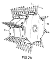
- the rotor 11 comprises an inner core 13 and a succession of transverse combs 14 spaced circumferentially around the rotor.
- Each tooth 15 of the comb has side edges 16 and 17 which diverge from each other in a direction away from the distal tip of the tooth 15.
- material including free grain, grain heads, and some straw, is dislodged by the edges of the apertures 21 of the teeth 15, and is impelled upwardly and rearwardly along the passage 33 to the auger 27.
- FIGs 3a and 3b show an improved form of the crop stripping elements 15 of Figure 2.
- Adjacent crop stripping elements 15 define a crop gathering region 22 which has an intake region 23 with inwardly converging boundaries formed by the side edges 16 and 17 of adjacent crop engaging elements 15.
- the crop gathering region 22 also has two succeeding relief regions 21A and 21B which succeed each other inwardly away from the distal ends of the elements 15.
- Each relief region is bounded by edges 20 of adjacent crop engaging elements.
- the entrance to the first relief region 21A is formed between respective junctions 24 and 25 of the inwardly converging boundaries 16 and 17 of the intake region 23, with the diverging boundaries 20 of the first relief region 21A.
- the entrance to the second relief region is formed by opposed cusps 26 and 27 produced by respective junctions 26 and 27 of the curved boundaries 20 of the first relief region 21A with the curved boundaries 20 of the second relief region 21B.
- the width of the entrance to each relief region 21A and 21B is less than the width of the relief region, and is less than the depth of the relief region in the inward direction away from the distal ends of the elements 15.
- the width of the entrance to a relief region is about half the width and is also about half the depth, of the relief region itself.
- the cusps 26 and 27 constitute opposed salients on the sides of adjacent elements 15, and the entrance to the second relief region 21B is formed between the opposed salients. It will be appreciated that in use, or in original manufacture, the opposed cusps 26 and 27 may be slightly rounded from the pointed shapes shown in the figure.
- the double keyhole shape shown in Figure 3b has been found to give improved stripping of crop, and reduced losses. It is believed that the following factors play a part in this improvement. It is believed that, with the double keyhole shown in Figure 3b, that stripping takes place in the first hole 21A of the keyhole, and the second hole 21B of the keyhole is available as a reservoir for already stripped crop stems. Thus when the rotor is well forward into the crop, crop stems which are already stripped can be held in the innermost hole 21B (the "reservoir") until release takes place as the machine moves forward. Fresh crop can pass from the inclined side edges 16 and 17 into the first hole 21A, and can be stripped in the most favourable manner by the edges of the first hole 21A.
- the opposed cusps 26 and 27 at the entrance to the second relief region 21B allow the easy passage of stripped stems away from the stripping aperture 21A into the reservoir aperture 21B as the machine moves forward, but at the same time provide sufficient pinch point between the two holes 21A and 21B to hold the stripped straw out of the way of the unstripped straw.
- the main dimensions which determine the form of the crop engaging elements are: the overall length of each crop engaging element 15, indicated at I; the length of the outer portion of each crop engaging element 15, beyond the entrance to the first relief aperture, indicated at II; the pitch of the tips of the crop engaging elements 15, that is to say the transverse distance between the tips, indicated at III; the diameter of the relief apertures 21A and 21B, indicated at IV; and the transverse width of the entrance to each relief aperture 21A and 21B, indicated at V.
- One guide which may be used in selecting these dimensions is that preferably the diameter IV of each relief region lies in the range of one quarter to one half, of the length II of the outer portion of the crop engaging element taken from the entrance to the first aperture, to the tip of the element, preferably the ratio being one third.
- the transverse width V of the entrance to a relief aperture is in the range one third to two thirds of the diameter IV of the relief aperture, most preferably about half the diameter of the aperture.
- the width of the entrance is set at half the width of the relief aperture, but is slightly greater than half the depth of the relief aperture.
- the diameter IV of a relief region lies in the range one third to two thirds of the pitch III of the tips of the elements, most preferably being equal to one half the pitch of the tips of the elements.
- the entrance to the second relief region is formed between opposed cusps on the sides of adjacent crop stripping elements.
- Numerous variations may be made in the shape of the cusps, and various criteria may be adopted in setting the shape. Because the sides of the salient are curved, the angle of approach of the sides will vary, but preferably is, when at its smallest value, about 90° or less than 90°.
Landscapes
- Life Sciences & Earth Sciences (AREA)
- Environmental Sciences (AREA)
- Harvesting Machines For Specific Crops (AREA)
- Outside Dividers And Delivering Mechanisms For Harvesters (AREA)
- Combines (AREA)
Claims (11)
- Vorrichtung zum Ernten benötigter Feldfruchtteile von einer stehenden Feldfrucht, mit
einem beweglichen Rahmen (12) zur Bewegung über dem Boden,
beweglichen Trägermitteln (11), die zur angetriebenen Bewegung relativ zum Rahmen (12) angebracht sind, und
einer Vielzahl von nach außen vorspringenden Feldfrucht-Greifelementen (15), die auf den beweglichen Trägermitteln (11) in zur Normalrichtung der Vorwärtsbewegung der Vorrichtung querstehenden Reihen angebracht sind,
Führungsmitteln (18), die mit den Feldfrucht-Greifelementen zusammenwirken, um einen Feldfrucht-Durchlaufkanal (33) zu bilden, und Antriebsmitteln zum Antreiben der beweglichen Trägermittel (11), um die Elemente (15) aufwärts an einem Vorderbereich der Vorrichtung zu fördern, um von der stehenden Feldfrucht vorbestimmte benötigte Feldfruchtteile abzutrennen und die abgetrennten Feldfruchtteile längs des Feldfrucht-Durchlaufkanals (33) zu bewegen, wobei die Feldfrucht-Greifelemente (15) so angeordnet sind, daß sie die stehende Feldfrucht ergreifen, während sie nach vorwärts bezüglich der Richtung der Vorwärtsbewegung der Vorrichtung vorspringen,
wobei die Feldfrucht-Greifelemente (15) so angeordnet sind, daß sie eine Vielzahl von Feldfrucht-Sammelbereichen (22) bilden, die jeweils einen Einlaßbereich (23) mit nach innen zulaufenden Randbereichen (16, 17) aufweisen, der zu wenigstens zwei nachfolgenden Freigabebereichen (21A, 21B) führt, welche nach innen weg von den entfernten (distal) Enden der Elemente (15) führen, wobei jeder Freigabebereich gekrümmte konkave Randbereiche (20) hat, die am Eingang zum Freigabebereich auseinanderlaufen und von den entfernten Enden der Feldfrucht-Greifelemente (15) wegzeigen, und die Breite des Eingangs zu jedem Freigabebereich (21A, 21B) kleiner ist als die Tiefe des Freigabebereichs in der Einwärts-Richtung weg von den entfernten Enden der Elemente (15), wobei jeder Feldfrucht-Sammelbereich (22) durch benachbarte Feldfrucht-Greifelemente (15) in derselben Querreihe definiert ist,
dadurch gekennzeichnet, daß der Eingang zu dem ersten Freigabebereich (21A) gebildet ist zwischen jeweiligen Übergängen (24, 25) der nach innen zulaufenden Grenzbereiche (16, 17) des Einlaßbereichs (23) zu den auseinanderlaufenden Teilen der gekrümmten konkaven Randbereiche (20) des ersten Freigabebereichs (21A), und der Eingang zu dem zweiten Freigabebereich (21B) gebildet ist zwischen gegenüberliegenden Wendepunkten bzw. Spitzen (26, 27) auf den Seiten der benachbarten Elemente (15), erzeugt durch jeweilige Übergänge (26, 27) der gekrümmten konkaven Randbereiche (20) des ersten Freigabebereichs (21A) zu den gekrümmten konkaven Randbereichen (20) des zweiten Freigabebereichs (21B). - Vorrichtung nach Anspruch 1, wobei der Randbereich (20) jedes Freigabebereichs im wesentlichen auf einem Kreis liegt.
- Vorrichtung nach Anspruch 1 oder 2, wobei jedes Feldfrucht-Greifelement (15) ein entferntes Ende hat, um in eine Feldfrucht einzudringen und sie zu zerteilen, und Seitenkanten (16, 17) hat, die auseinanderlaufen in einer Richtung weg von der entfernten Spitze des Elementes, wobei jedes Feldfrucht-Greifelement (15) eine Oberfläche quer zur Bewegungsrichtung des Elementes (15) hat durch die beweglichen Trägermittel (11), um die abgetrennten Feldfruchteile längs des Feldfrucht-Durchlaufkanals anzutreiben.
- Vorrichtung nach Anspruch 1, 2 oder 3, wobei die Feldfrucht-Abtrennelemente (15) so angeordnet sind, daß Elemente, die einander um die Trägermittel (11) folgen, miteinander ausgerichtet sind bzw. fluchten.
- Vorrichtung nach einem vorhergehenden Anspruch, wobei die beweglichen Trägermittel (11) einen Rotor aufweisen, und die Führungsmittel (18) einen Deckel aufweisen, der sich wenigstens um einen Teil des Bereichs erstreckt, an dem sich die Feldfrucht-Greifelemente an dem Vorderbereich der Vorrichtung nach oben bewegen.
- Vorrichtung nach einem vorhergehenden Anspruch, wobei jede Spitze (26, 27) gebildet ist an dem Schnittpunkt von zwei Kreisen, wobei die Tangenten an den Kreisen an dem Schnittpunkt gegeneinander in weniger als 90° geneigt sind.
- Verfahren zum Ernten von Feldfrüchten, mit
Bewegen einer Erntevorrichtung durch eine stehende Feldfrucht,
Bewegen einer Vielzahl von nach außen vorspringenden Feldfrucht-Greifelementen (15), die in Reihen quer zur normalen Richtung der Vorwärtsbewegung der Vorrichtung angeordnet sind, an einem Vorderbereich der Vorrichtung,
Greifen der stehenden Feldfrucht durch die sich bewegenden Elemente (15), wenn sie vorwärts bezüglich der Bewegungsrichtung der Vorrichtung vorspringen,
Sammeln von Feldfrüchten in Feldfrucht-Sammelbereichen der Elemente mit Randbereichen (16, 17), die nach innen weg von den entfernten Enden der Elemente (15) zulaufen,
Führen der Feldfrüchte zu wenigstens zwei nachfolgenden Freigabebereichen (21A, 21B), die an dem Übergang der benachbarten Feldfrucht-Greifelemente (15) in derselben Querreihe vorgesehen sind und die nach innen weg von den entfernten Enden der Elemente (15) führen, wobei jeder Freigabebereich (21A, 21B) gekrümmte konkave Randbereiche (20) hat, die am Eingang zu dem Freigabebereich auseinanderlaufen und weg von den entfernten Enden der Feldfrucht-Greifelemente (15) zeigen, und die Breite des Eingangs zu jedem Freigabebereich (21A, 21B) kleiner ist als die Tiefe dieses Freigabebereichs in der Einwärts-Richtung weg von den entfernten Enden der Elemente (15), Abtrennen von Feldfruchtteilen durch die Wirkung der Kanten der Elemente (15),
Halten der abgetrennten Feldfruchtstiele zwischen benachbarten Elementen (15) vor der Lösung aufgrund der Vorwärtsbewegung der Vorrichtung, und Freigeben verbleibender abgetrennter Feldfruchtstiele von den Elementen (15),
dadurch gekennzeichnet, daß die Führungs- und Halteschritte aufweisen; Führen der Feldfrucht direkt von dem Einlaßbereich (23) in den ersten Freigabebereich (21A) durch den Eingang dafür, der gebildet ist zwischen jeweiligen Übergängen (24, 25) der nach innen zulaufenden Randbereiche (16, 17) des Einlaßbereiches (23) zu den auseinanderlaufenden Teilen der gekrümmten konkaven Randbereiche (20) des ersten Freigabebereiches (21A), und
Halten der abgetrennten Feldfruchtstiele in dem zweiten Freigabebereich (21B), und zwar vor der Lösung aufgrund der Vorwärtsbewegung der Vorrichtung, und zwar vermittels gegenüberliegender Spitzen bzw. Wendepunkte (26, 27) auf den Seiten benachbarter Elemente, erzeugt durch jeweilige Übergänge (26, 27) der gekrümmten konkaven Randbereiche (20) des ersten Freigabebereichs (21A) zu den gekrümmten konkaven Randbereichen (20) des zweiten Freigabebereichs (21B) an dem Eingang zu dem zweiten Freigabebereich (21B). - Verfahren nach Anspruch 7, wobei der Schritt des Ablösens von Feldfruchtteilen das Ablösen der Feldfruchtteile von Bereichen der stehenden Feldfrucht aufweist, die bezüglich der Bewegungrichtung der Vorrichtung nach vorn zeigen, und zwar durch Kanten (20) der Feldfrucht-Greifelemente (15), die von den entfernten Enden der Elemente wegzeigen.
- Verfahren nach Anspruch 7 oder 8, mit dem Schritt des Antreibens der abgelösten Feldfruchtteile längs des Feldfrucht-Durchlaufkanals (33) vermittels querliegender Oberflächen, die auf den Elementen (15) vorgesehen sind.
- Verfahren nach einem der Ansprüche 7 bis 9, mit dem Schritt des Eindringens in und Trennens von Feldfrüchten durch entfernte Spitzen der Feldfrucht-Greifelemente (15) mit Seitenkanten (16, 17), die auseinanderlaufen in einer Richtung von der entfernten Spitze des Elementes (15) weg.
- Verfahren nach einem der Ansprüche 7 bis 10, mit dem Schritt des Antreibens der abgelösten Feldfruchtteile längs des Feldfrucht-Durchlaufkanals (33) durch die Feldfrucht-Greifelemente (15) in einem sich schnell bewegenden Strom.
Applications Claiming Priority (3)
| Application Number | Priority Date | Filing Date | Title |
|---|---|---|---|
| GB898918015A GB8918015D0 (en) | 1989-08-07 | 1989-08-07 | Crop harvesting apparatus |
| GB8918015 | 1989-08-07 | ||
| PCT/GB1990/001225 WO1991001626A1 (en) | 1989-08-07 | 1990-08-06 | Crop harvesting apparatus |
Publications (2)
| Publication Number | Publication Date |
|---|---|
| EP0437578A1 EP0437578A1 (de) | 1991-07-24 |
| EP0437578B1 true EP0437578B1 (de) | 1994-06-08 |
Family
ID=10661282
Family Applications (1)
| Application Number | Title | Priority Date | Filing Date |
|---|---|---|---|
| EP90912099A Expired - Lifetime EP0437578B1 (de) | 1989-08-07 | 1990-08-06 | Erntevorrichtung |
Country Status (9)
| Country | Link |
|---|---|
| US (1) | US5175984A (de) |
| EP (1) | EP0437578B1 (de) |
| AU (1) | AU640948B2 (de) |
| CA (1) | CA2038783C (de) |
| DE (1) | DE69009723T2 (de) |
| DK (1) | DK0437578T3 (de) |
| ES (1) | ES2057581T3 (de) |
| GB (2) | GB8918015D0 (de) |
| WO (1) | WO1991001626A1 (de) |
Families Citing this family (14)
| Publication number | Priority date | Publication date | Assignee | Title |
|---|---|---|---|---|
| US5501067A (en) * | 1994-07-29 | 1996-03-26 | Brown; Claude E. | Selective harvesting machine |
| WO1996012400A1 (en) * | 1994-10-25 | 1996-05-02 | Bjurenvall, Ingemar | System for harvesting crops by combing |
| US5551221A (en) * | 1995-03-01 | 1996-09-03 | Sund; Lloyd P. | Replaceable pick-up tooth assembly for crop pick-up |
| US5557912A (en) * | 1995-06-13 | 1996-09-24 | Western Combine Corporation | Stripper header attachment |
| GB9816213D0 (en) | 1998-07-24 | 1998-09-23 | Shelbourne Reynolds Eng | Crop strippers and stripper toothing |
| US7820878B2 (en) * | 1999-11-19 | 2010-10-26 | Kyowa Hakko Kirin Co., Ltd. | Production of ungulates, preferably bovines that produce human immunoglobulins |
| GB2424166A (en) * | 2005-03-18 | 2006-09-20 | Ian Fletcher | Harvesting and sowing system and apparatus |
| DE102014102694A1 (de) * | 2014-02-28 | 2015-09-03 | Leibniz-Institut für Agrartechnik Potsdam-Bornim e.V.(ATB) | Vorrichtung und Verfahren zum Pflücken von Blüten von Blütenpflanzen |
| DE102014014871B8 (de) | 2014-10-06 | 2016-05-19 | Lucian Andrej Fink | Erntevorrichtung für Getreide, Reis, Samen und Körner |
| US11485031B2 (en) * | 2015-03-06 | 2022-11-01 | Katherine Waymire | Herb-stripping devices, assemblies, and components |
| WO2020069611A1 (fr) * | 2018-10-02 | 2020-04-09 | Les Machineries Pronovost Inc. | Panier à peigne et ensemble nettoyeur pour un système de récolte d'asclépiade, et ledit système de récolte |
| AR116260A1 (es) * | 2019-08-02 | 2021-04-21 | Huergo Hector Augusto | Cabezal para cosecha |
| WO2024010949A1 (en) * | 2022-07-07 | 2024-01-11 | Applequist Mfg. Inc. | Crop stripper rotor with dynamic balancing system |
| US20250261588A1 (en) * | 2024-02-21 | 2025-08-21 | Concurrent Engineering Inc. | Multi section flexible stripper header |
Citations (1)
| Publication number | Priority date | Publication date | Assignee | Title |
|---|---|---|---|---|
| AU6011665A (en) * | 1966-06-15 | 1967-12-21 | William Alfred Dunstan | A trash stripper for the preparation of planting cane |
Family Cites Families (5)
| Publication number | Priority date | Publication date | Assignee | Title |
|---|---|---|---|---|
| US4578937A (en) * | 1984-05-21 | 1986-04-01 | Deere & Company | Harvester machine for stripping seeds from a standing crop |
| GB8424395D0 (en) * | 1984-09-27 | 1984-10-31 | British Res Agricult Eng | Crop harvesting |
| GB8608585D0 (en) * | 1986-04-09 | 1986-05-14 | British Res Agricult Eng | Crop harvesting apparatus |
| US4843806A (en) * | 1984-09-27 | 1989-07-04 | National Research Development Corporation | Crop harvesting apparatus and methods |
| AU1080288A (en) * | 1987-01-05 | 1988-07-27 | Wilfred Erwin Klinner | Apparatus and method for harvesting crops |
-
1989
- 1989-08-07 GB GB898918015A patent/GB8918015D0/en active Pending
-
1990
- 1990-08-06 WO PCT/GB1990/001225 patent/WO1991001626A1/en not_active Ceased
- 1990-08-06 DE DE69009723T patent/DE69009723T2/de not_active Expired - Fee Related
- 1990-08-06 CA CA002038783A patent/CA2038783C/en not_active Expired - Fee Related
- 1990-08-06 DK DK90912099.0T patent/DK0437578T3/da active
- 1990-08-06 ES ES90912099T patent/ES2057581T3/es not_active Expired - Lifetime
- 1990-08-06 AU AU62740/90A patent/AU640948B2/en not_active Ceased
- 1990-08-06 EP EP90912099A patent/EP0437578B1/de not_active Expired - Lifetime
- 1990-08-06 US US07/671,790 patent/US5175984A/en not_active Expired - Lifetime
-
1991
- 1991-03-14 GB GB9105433A patent/GB2240455B/en not_active Revoked
Patent Citations (1)
| Publication number | Priority date | Publication date | Assignee | Title |
|---|---|---|---|---|
| AU6011665A (en) * | 1966-06-15 | 1967-12-21 | William Alfred Dunstan | A trash stripper for the preparation of planting cane |
Also Published As
| Publication number | Publication date |
|---|---|
| US5175984A (en) | 1993-01-05 |
| GB9105433D0 (en) | 1991-05-01 |
| EP0437578A1 (de) | 1991-07-24 |
| DE69009723D1 (de) | 1994-07-14 |
| AU640948B2 (en) | 1993-09-09 |
| GB8918015D0 (en) | 1989-09-20 |
| DK0437578T3 (da) | 1994-07-11 |
| WO1991001626A1 (en) | 1991-02-21 |
| AU6274090A (en) | 1991-03-11 |
| DE69009723T2 (de) | 1995-01-26 |
| GB2240455B (en) | 1993-09-29 |
| ES2057581T3 (es) | 1994-10-16 |
| CA2038783A1 (en) | 1991-02-08 |
| GB2240455A (en) | 1991-08-07 |
| CA2038783C (en) | 2001-02-13 |
Similar Documents
| Publication | Publication Date | Title |
|---|---|---|
| EP0241276B1 (de) | Erntemaschine für Feldfrüchte und Verfahren | |
| EP0437578B1 (de) | Erntevorrichtung | |
| AU599577B2 (en) | Crop harvesting apparatus & methods | |
| EP0340229B1 (de) | Apparat und verfahren zum ernten von feldfrüchten | |
| US4516390A (en) | Apparatus and method of picking up and conveying cut crop | |
| US5419107A (en) | Crop stripping apparatus | |
| CN100566547C (zh) | 甘蔗联合收割机 | |
| EP1009214B1 (de) | Pflückvorsatz für eine erntemaschine | |
| CN107960197A (zh) | 一种叶片收割机 | |
| CN107969214A (zh) | 菊花采收机及菊花采收方法 | |
| US4951453A (en) | Crop harvesting apparatus and methods | |
| US4991385A (en) | Crop harvesting apparatus and methods | |
| GB2207847A (en) | Crop harvesting apparatus and methods | |
| CN113348846A (zh) | 一种三垄六行花生有序铺放收获机 | |
| CN207948180U (zh) | 一种叶片收割机 | |
| CN217644234U (zh) | 一种辣椒采摘割台 | |
| CN215122121U (zh) | 一种三垄六行花生有序铺放收获机 | |
| FI83585C (fi) | Skoerdeanordning och -foerfaranden. | |
| CA1324725C (en) | Crop harvesting apparatus and methods | |
| JP3155517B2 (ja) | コンバインの茎稈掻込装置 | |
| JPH0135635Y2 (de) | ||
| SU1186124A1 (ru) | Подборщик валков к сельскохоз йственной уборочной машине | |
| JPS5863315A (ja) | 刈取機の掻込装置 | |
| CN2329164Y (zh) | 一种与割前脱粒收获机相配套的禾秆切割装置 | |
| JPS60145014A (ja) | コンバイン |
Legal Events
| Date | Code | Title | Description |
|---|---|---|---|
| PUAI | Public reference made under article 153(3) epc to a published international application that has entered the european phase |
Free format text: ORIGINAL CODE: 0009012 |
|
| 17P | Request for examination filed |
Effective date: 19910319 |
|
| AK | Designated contracting states |
Kind code of ref document: A1 Designated state(s): BE DE DK ES FR GB IT NL SE |
|
| RAP1 | Party data changed (applicant data changed or rights of an application transferred) |
Owner name: BRITISH TECHNOLOGY GROUP PLC |
|
| RAP3 | Party data changed (applicant data changed or rights of an application transferred) |
Owner name: BRITISH TECHNOLOGY GROUP LTD |
|
| 17Q | First examination report despatched |
Effective date: 19920914 |
|
| GRAA | (expected) grant |
Free format text: ORIGINAL CODE: 0009210 |
|
| AK | Designated contracting states |
Kind code of ref document: B1 Designated state(s): BE DE DK ES FR GB IT NL |
|
| ITF | It: translation for a ep patent filed | ||
| REG | Reference to a national code |
Ref country code: DK Ref legal event code: T3 |
|
| REF | Corresponds to: |
Ref document number: 69009723 Country of ref document: DE Date of ref document: 19940714 |
|
| ET | Fr: translation filed | ||
| REG | Reference to a national code |
Ref country code: ES Ref legal event code: FG2A Ref document number: 2057581 Country of ref document: ES Kind code of ref document: T3 |
|
| PLBE | No opposition filed within time limit |
Free format text: ORIGINAL CODE: 0009261 |
|
| STAA | Information on the status of an ep patent application or granted ep patent |
Free format text: STATUS: NO OPPOSITION FILED WITHIN TIME LIMIT |
|
| 26N | No opposition filed | ||
| REG | Reference to a national code |
Ref country code: GB Ref legal event code: IF02 |
|
| PGFP | Annual fee paid to national office [announced via postgrant information from national office to epo] |
Ref country code: GB Payment date: 20050803 Year of fee payment: 16 Ref country code: NL Payment date: 20050803 Year of fee payment: 16 |
|
| PGFP | Annual fee paid to national office [announced via postgrant information from national office to epo] |
Ref country code: DE Payment date: 20050804 Year of fee payment: 16 |
|
| PGFP | Annual fee paid to national office [announced via postgrant information from national office to epo] |
Ref country code: FR Payment date: 20050809 Year of fee payment: 16 |
|
| PGFP | Annual fee paid to national office [announced via postgrant information from national office to epo] |
Ref country code: DK Payment date: 20050815 Year of fee payment: 16 |
|
| PGFP | Annual fee paid to national office [announced via postgrant information from national office to epo] |
Ref country code: ES Payment date: 20050927 Year of fee payment: 16 |
|
| PGFP | Annual fee paid to national office [announced via postgrant information from national office to epo] |
Ref country code: BE Payment date: 20051013 Year of fee payment: 16 |
|
| PG25 | Lapsed in a contracting state [announced via postgrant information from national office to epo] |
Ref country code: DK Free format text: LAPSE BECAUSE OF NON-PAYMENT OF DUE FEES Effective date: 20060831 Ref country code: BE Free format text: LAPSE BECAUSE OF NON-PAYMENT OF DUE FEES Effective date: 20060831 |
|
| PGFP | Annual fee paid to national office [announced via postgrant information from national office to epo] |
Ref country code: IT Payment date: 20060831 Year of fee payment: 17 |
|
| PG25 | Lapsed in a contracting state [announced via postgrant information from national office to epo] |
Ref country code: DE Free format text: LAPSE BECAUSE OF NON-PAYMENT OF DUE FEES Effective date: 20070301 Ref country code: NL Free format text: LAPSE BECAUSE OF NON-PAYMENT OF DUE FEES Effective date: 20070301 |
|
| REG | Reference to a national code |
Ref country code: DK Ref legal event code: EBP |
|
| GBPC | Gb: european patent ceased through non-payment of renewal fee |
Effective date: 20060806 |
|
| NLV4 | Nl: lapsed or anulled due to non-payment of the annual fee |
Effective date: 20070301 |
|
| REG | Reference to a national code |
Ref country code: FR Ref legal event code: ST Effective date: 20070430 |
|
| REG | Reference to a national code |
Ref country code: ES Ref legal event code: FD2A Effective date: 20060807 |
|
| PG25 | Lapsed in a contracting state [announced via postgrant information from national office to epo] |
Ref country code: GB Free format text: LAPSE BECAUSE OF NON-PAYMENT OF DUE FEES Effective date: 20060806 |
|
| BERE | Be: lapsed |
Owner name: BRITISH *TECHNOLOGY GROUP LTD Effective date: 20060831 |
|
| PG25 | Lapsed in a contracting state [announced via postgrant information from national office to epo] |
Ref country code: ES Free format text: LAPSE BECAUSE OF NON-PAYMENT OF DUE FEES Effective date: 20060807 |
|
| PG25 | Lapsed in a contracting state [announced via postgrant information from national office to epo] |
Ref country code: FR Free format text: LAPSE BECAUSE OF NON-PAYMENT OF DUE FEES Effective date: 20060831 |
|
| PG25 | Lapsed in a contracting state [announced via postgrant information from national office to epo] |
Ref country code: IT Free format text: LAPSE BECAUSE OF NON-PAYMENT OF DUE FEES Effective date: 20070806 |