EP0437245A2 - Finger joint cutter machine and method - Google Patents
Finger joint cutter machine and method Download PDFInfo
- Publication number
- EP0437245A2 EP0437245A2 EP91100204A EP91100204A EP0437245A2 EP 0437245 A2 EP0437245 A2 EP 0437245A2 EP 91100204 A EP91100204 A EP 91100204A EP 91100204 A EP91100204 A EP 91100204A EP 0437245 A2 EP0437245 A2 EP 0437245A2
- Authority
- EP
- European Patent Office
- Prior art keywords
- finger
- tables
- boards
- pivoted
- cutter
- Prior art date
- Legal status (The legal status is an assumption and is not a legal conclusion. Google has not performed a legal analysis and makes no representation as to the accuracy of the status listed.)
- Granted
Links
Images


Classifications
-
- B—PERFORMING OPERATIONS; TRANSPORTING
- B27—WORKING OR PRESERVING WOOD OR SIMILAR MATERIAL; NAILING OR STAPLING MACHINES IN GENERAL
- B27M—WORKING OF WOOD NOT PROVIDED FOR IN SUBCLASSES B27B - B27L; MANUFACTURE OF SPECIFIC WOODEN ARTICLES
- B27M3/00—Manufacture or reconditioning of specific semi-finished or finished articles
- B27M3/0013—Manufacture or reconditioning of specific semi-finished or finished articles of composite or compound articles
- B27M3/0026—Manufacture or reconditioning of specific semi-finished or finished articles of composite or compound articles characterised by oblong elements connected laterally
- B27M3/0053—Manufacture or reconditioning of specific semi-finished or finished articles of composite or compound articles characterised by oblong elements connected laterally using glue
-
- B—PERFORMING OPERATIONS; TRANSPORTING
- B27—WORKING OR PRESERVING WOOD OR SIMILAR MATERIAL; NAILING OR STAPLING MACHINES IN GENERAL
- B27D—WORKING VENEER OR PLYWOOD
- B27D1/00—Joining wood veneer with any material; Forming articles thereby; Preparatory processing of surfaces to be joined, e.g. scoring
- B27D1/10—Butting blanks of veneer; Joining same along edges; Preparatory processing of edges, e.g. cutting
-
- B—PERFORMING OPERATIONS; TRANSPORTING
- B27—WORKING OR PRESERVING WOOD OR SIMILAR MATERIAL; NAILING OR STAPLING MACHINES IN GENERAL
- B27F—DOVETAILED WORK; TENONS; SLOTTING MACHINES FOR WOOD OR SIMILAR MATERIAL; NAILING OR STAPLING MACHINES
- B27F1/00—Dovetailed work; Tenons; Making tongues or grooves; Groove- and- tongue jointed work; Finger- joints
- B27F1/02—Making tongues or grooves, of indefinite length
-
- B—PERFORMING OPERATIONS; TRANSPORTING
- B27—WORKING OR PRESERVING WOOD OR SIMILAR MATERIAL; NAILING OR STAPLING MACHINES IN GENERAL
- B27F—DOVETAILED WORK; TENONS; SLOTTING MACHINES FOR WOOD OR SIMILAR MATERIAL; NAILING OR STAPLING MACHINES
- B27F1/00—Dovetailed work; Tenons; Making tongues or grooves; Groove- and- tongue jointed work; Finger- joints
- B27F1/16—Making finger joints, i.e. joints having tapers in the opposite direction to those of dovetail joints
-
- B—PERFORMING OPERATIONS; TRANSPORTING
- B27—WORKING OR PRESERVING WOOD OR SIMILAR MATERIAL; NAILING OR STAPLING MACHINES IN GENERAL
- B27M—WORKING OF WOOD NOT PROVIDED FOR IN SUBCLASSES B27B - B27L; MANUFACTURE OF SPECIFIC WOODEN ARTICLES
- B27M3/00—Manufacture or reconditioning of specific semi-finished or finished articles
- B27M3/0013—Manufacture or reconditioning of specific semi-finished or finished articles of composite or compound articles
- B27M3/002—Manufacture or reconditioning of specific semi-finished or finished articles of composite or compound articles characterised by oblong elements connected at their ends
-
- B—PERFORMING OPERATIONS; TRANSPORTING
- B30—PRESSES
- B30B—PRESSES IN GENERAL
- B30B1/00—Presses, using a press ram, characterised by the features of the drive therefor, pressure being transmitted directly, or through simple thrust or tension members only, to the press ram or platen
- B30B1/02—Presses, using a press ram, characterised by the features of the drive therefor, pressure being transmitted directly, or through simple thrust or tension members only, to the press ram or platen by lever mechanism
- B30B1/08—Presses, using a press ram, characterised by the features of the drive therefor, pressure being transmitted directly, or through simple thrust or tension members only, to the press ram or platen by lever mechanism operated by fluid-pressure means
Definitions
- the invention relates to a finger joint milling machine for the production of finger joints on the end face of boards which are to be glued on the end face in continuous succession or individually with boards provided with corresponding finger joints.
- the object of the invention was to significantly reduce the space and cost of a finger jointing system and, on the other hand, to increase its performance and to simplify its operation.
- the invention enables a considerable improvement and effective acceleration of the processing of the boards intended for plywood beams.
- the automatically feedable boards are milled and glued on both sides in one programmable operation. They can then be automatically transported to the finger press again. Manual work, in particular lifting the boards around is avoided
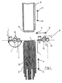
- the finger jointing machine shown in FIG. 1 has two tables 3 and 4 which can be displaced relative to one another in the direction of arrows 1 and 2, over which the boards 5 to be machined, lying upright and arranged in a stack, are pushed and aligned by a stop 6 for processing.
- the milling device 9 can be displaced in front of the end faces of the boards 5 by working cylinders, not shown.
- the milling device 9 consists of a chipper 10 for cutting the ends of the boards 5 in the plane of the dashed line 11, the milling cutter 12 having a finger joint profile for cutting the finger joints and the glue dispensing device 13 with which the cut finger joints are provided with glue. Chipper 11, milling machine 12 and glue dispenser 13 are arranged on a common console, not shown.
- the milling device 9 can be pivoted about the vertical axis 14 of the milling cutter 14 by 180 ° on this console.
- the mode of operation is as follows:
- the boards 5, which have different lengths, are pushed onto the table 3 when it moves back in the direction of arrow 2 and when it moves forward in the direction of arrow 1 at the stop 6 which is then moved into the position of the broken line 11 aligned so that their end faces are in the plane of the chipper 10.
- the milling device 9 then moves in the direction of Arrow 7 through, cuts the ends of the boards 5 smooth, milled the finger joints and provides them with glue, as shown in Figure 2a.
- the milling device 9 travels to position 15 and pivots there about the axis 14 of the milling cutter 12 by 180 °.
- the tables 3 and 4 move towards one another, the table 4 taking over the stack of boards 5 when the tables 3 and 4 move apart again in the direction of the arrows 1 and 2.
- the boards 5 are aligned when the table 4 is moved back in the direction of arrow 2 at its other end to the dashed line 11 and cut smooth in the direction of arrow 8, milled on finger joints and with Apply glue, as shown in Figure 2 b.
- the finger jointing machine 9 is pivoted back into its original position by 180 ° in order to trim the next stack of boards arriving.
- the boards 5 of different lengths are then provided at both ends with geometrically exactly the same and glued finger joints and can now be conveyed one after the other into the finger press and assembled there to form an endless belt.
- the tables 16 and 17 are pivotable about the vertical axes 18 and 19 in the horizontal plane, so that bevel cuts are possible.
- the arrangement of the finger jointing machine 20 is the same as that shown in FIG. 1 However, instead of the chipper 10, a circular saw 10 'is provided, since here the boards have to be cut through at an angle, as shown at 20, and not just dressed.
- the finger joint milling machine turns here in the same way, if it has trimmed the boards on one end side, after swiveling through 180 ° in order to machine the other ends of the boards 5, and swivels back again after reaching its starting position by 180 °
- FIG. 4 shows wooden structures made of plywood support parts that can be produced with boards that are cut to size according to FIG. 3 and are provided with finger joints.
Landscapes
- Life Sciences & Earth Sciences (AREA)
- Engineering & Computer Science (AREA)
- Wood Science & Technology (AREA)
- Forests & Forestry (AREA)
- Mechanical Engineering (AREA)
- Manufacturing & Machinery (AREA)
- Veneer Processing And Manufacture Of Plywood (AREA)
- Dovetailed Work, And Nailing Machines And Stapling Machines For Wood (AREA)
- Saccharide Compounds (AREA)
- Finger-Pressure Massage (AREA)
- Scissors And Nippers (AREA)
- Dental Tools And Instruments Or Auxiliary Dental Instruments (AREA)
- Surgical Instruments (AREA)
- Electrophonic Musical Instruments (AREA)
- Wire Bonding (AREA)
- Orthopedics, Nursing, And Contraception (AREA)
- Seal Device For Vehicle (AREA)
- Lining Or Joining Of Plastics Or The Like (AREA)
Abstract
Description
Die Erfindung betrifft eine Keilzinkenfräse zur Herstellung von Keilzinken an der Stirnseite von Brettern, die mit mit entsprechenden Keilzinken versehenen Brettern stirnseitig in fortlaufender Folge oder einzeln verleimt werden sollen.The invention relates to a finger joint milling machine for the production of finger joints on the end face of boards which are to be glued on the end face in continuous succession or individually with boards provided with corresponding finger joints.
Bei herkömmlichen Verfahren zur Herstellung von Keilverzinkungen werden Bretter unterschiedlicher Länge hochkant stehend auf einen Frästisch zu Stapeln unter Ausrichten an einer ihrer Stirnseiten zusammengefaßt und dort mit einem Zerspahner oder einer Kreissäge im rechte Winkel zu den Brettersäumen geradegeschnitten. Sodann werden die 10 bis 30 cm langen Keilzinken von einem Profilfräser herausgeschnitten und anschließend mit Leim angegeben. Die Bretter werden im nächsten Schritt an ihren anderen Stirnseiten aufeinander ausgerichtet und von einem zweiten Satz der gleichen Maschinen mit Keilzinken versehen, die mit Leim angegeben werden. Die so bearbeiteten Bretter werden anschließend mit ihren Zinkenprofilen zusammengefügt und während des Abbindens des Leims in einer Keilzinkenpresse verpreßt.In conventional methods for the production of finger joints, boards of different lengths are stacked upright on a milling table and aligned on one of their end faces, where they are cut straight at right angles to the board edges using a cutter or a circular saw. Then the 10 to 30 cm long finger tines are cut out by a profile cutter and then given with glue. In the next step, the boards are aligned with each other on their other faces and are finger-jointed by a second set of the same machines, which are given with glue. The so processed boards are then joined together with their tine profiles and pressed in a finger press during the setting of the glue.
Bei der so gegebenen Notwendigkeit der Verwendung zweier Profil-fräsen für die beiden Bretterenden muß die Geometrie der beiderseitigen Werkzeuge genau aufeinander verpaßt sein, um beim Zusammensetzen der Bretter zu Bahnen einen völlig exakten Fugenverlauf zu erhalten und Verbindungslücken oder Verquetschungen zu vermeiden, vorallem aber um eine Verleimung der Zinken auf ihre gesamte Länge sicherzustellen. Die Verbindung der Bretter muß so sein, daß sie in ihrer statischen Belastbarkeit der von gewachsenem Holz entspricht. Es entstehen also Anpassungsprobleme beim Nachschleifen der Werkzeuge, was zu zeitraubenden Produktionsunterbrechungen führt. Auch erfordert der doppelte Satz von Bearbeitungsmaschinen erheblichen Stellraum. Es wurde vorgeschlagen, den Fräßtisch für die 5 m und mehr langen Bretter einen um 180° schwenkbaren Frästisch anzuordnen, um mit nur einem Satz der Bearbeitungsmaschinen auszukommen, da dann beide Enden des Bretterstapels an der selben Stelle zugerichtet werden können, doch dann ergibt sich ein noch größerer Platzbedarf und eine Verminderung der Leistung je Zeiteinheit.Given the need to use two profile milling cutters for the two board ends, the geometry of the tools on both sides must be precisely matched to one another in order to obtain a completely exact joint course when assembling the boards into strips and to avoid connection gaps or crushing, but above all by one Ensure that the tines are glued along their entire length. The connection of the boards must be such that their static load capacity corresponds to that of grown wood. So there are adjustment problems when regrinding the tools, which leads to time-consuming production interruptions. The double set of processing machines also requires considerable space. It has been proposed to arrange the milling table for the 5 m and more long boards with a milling table which can be swiveled through 180 ° in order to get by with only one set of the processing machines, since both ends of the board stack can then be trimmed in the same place, but this results in even larger space requirements and a reduction in performance per unit of time.
Aufgabe der Erfindung war es, Platzbedarf und Kostenaufwand für eine Keilzinkenfräsanlage wesentlich zu verringern und andererseits ihre Leistung zu erhöhen wie auch ihre Bedienung zu vereinfachen.The object of the invention was to significantly reduce the space and cost of a finger jointing system and, on the other hand, to increase its performance and to simplify its operation.
Diese Aufgabe wird mit den in den Ansprüchen angegebenen Maßnahmen gelöst.This object is achieved with the measures specified in the claims.
Die Erfindung ermöglicht eine erhebliche Verbesserung und wirkungsvolle Beschleunigung der Bearbeitung der für Schichtholzträger bestimmten Bretter. Die automatisch zuführbaren Bretter werden in einem programmierbaren Arbeitsgang beiderseits gefräst und eingeleimt. Sie können dann wieder automatisch zur Keilzinkenpresse transportiert werden. Handarbeit, insbesondere das Herumheben der Bretter ist vermiedenThe invention enables a considerable improvement and effective acceleration of the processing of the boards intended for plywood beams. The automatically feedable boards are milled and glued on both sides in one programmable operation. They can then be automatically transported to the finger press again. Manual work, in particular lifting the boards around is avoided
Ausführungsbeispiele der Erfindung werden im folgenden an Hand der Zeichnungen näher beschrieben. Es zeigen in schematischer Darstellung
- Fig.1
- eine Draufsicht auf eine erfindungsgemäße Keilzinkenpresse
- Fig.2
- a) die gleiche Keilzinkenfräse bei Beginn des Fräsens der Stirnseite eines Bretterstapels
b) bei Beginn des Fräsens der anderen Stirnseite des gleichen Bretterstapels - Fig.3
- eine andere Ausführungsform eine erfindungsgemäßen Keilzinkenfräse
- Fig.4
- Beispiele der mi der Keilzinkenfräse gemäß Fig.3 herstellbaren Holzkonstruktionen.
- Fig. 1
- a plan view of a finger press according to the invention
- Fig. 2
- a) the same finger jointing machine at the start of milling the end face of a stack of boards
b) at the start of milling the other end face of the same board stack - Fig. 3
- another embodiment of a finger jointing machine according to the invention
- Fig. 4
- Examples of the wooden constructions that can be produced with the finger joint milling machine according to FIG. 3.
Die in Figur 1 dargestellte Keilzinkenfräse weist zwei gegeneinander in Richtung der Pfeile 1 und 2 verschiebbaren Tishe 3 und 4 auf, über die die zu bearbeitenden, hochkant liegendenden und zu einem Stapel geordneten Bretter 5 geschoben und durch einen Anschlag 6 zur Bearbeitung ausgerichtet werden. In Richtung der Pfeile 7 und 8 ist die Fräsvorrichtung 9 vor den Stirnseiten der Bretter 5 durch nicht dargestellte Arbeitszylinder verschiebbar. Die Fräsvorrichtung 9 besteht aus einem Zerspaner 10 zum Geradeschneiden der Enden der Bretter 5 in der Ebene der gestrichelten Linie 11, der ein Keilzinkenprofil aufweisenden Fräse 12 zum Schneiden der Keilzinken und der Leimangabevorrichtung 13, mit der die geschnittenen Keilzinken mit Leim versehen werden. Zerspaner 11, Fräse 12 und Leimangabevorrichtung 13 sind auf einer gemeinsamen nicht dargestellten Konsole angeordnet. Die Fräsvorrichtung 9 ist um die senkrechte Achse 14 der Fräse 14 um 180° auf dieser Konsole schwenkbar.The finger jointing machine shown in FIG. 1 has two tables 3 and 4 which can be displaced relative to one another in the direction of
Die Wirkungsweise ist folgende: Die Bretter 5, die verschiedene Längen aufweisen, werden auf den Tisch 3 bei dessen Zurückfahren in Richtung des Pfeiles 2 aufgeschoben und bei dessen Wiedervorfahren in Richtung des Pfeiles 1 an dem dann in die Lage der gestrichelten Linie 11 versetzten Anschlag 6 ausgerichtet, sodaß ihre Stirnseiten in der Ebene des Zerspaners 10 liegen Die Fräsvorrichtung 9 fährt dann in Richtung des Pfeiles 7 durch, schneidet die Enden der Bretter 5 glatt, fräst die Keilzinken und versieht sie mit Leim, wie dies in Figur 2 a dargestellt ist. Die Fräsvorrichtung 9 fährt bis zur Position 15 durch und schwenkt dort um die Achse 14 der Fräse 12 um 180°. Gleichzeitig fahren die Tische 3 und 4 aufeinander zu, wobei der Tisch 4 den Stapel der Bretter 5 beim erneuten Auseinanderfahren der Tische 3 und 4 in Richtung der Pfeile 1 und 2 übernimmt. Nach Versetzen des Anschlages 6 in die in Figur 1 gezeigte Stellung werden die Bretter 5 bei Wiederzurückfahren des Tisches 4 in Richtung des Pfeiles 2 an ihrem anderen Ende auf die gestrichelte Linie 11 ausgerichtet und in der Richtung des Pfeiles 8 glattgeschnitten, auf Keilzinken gefräst und mit Leim versehen, wie dies Figur 2 b zeigt. In ihrer Endposition wird die Keilzinkenfräse 9 wieder um 180° in ihre ursprüngliche Stellung zurückgeschwenkt, um den nächsten ankommenden Bretterstapel zu beschneiden.The mode of operation is as follows: The
Die verschiedenlangen Bretter 5 sind dann an beiden Enden mit geometrisch genau gleichen und beleimten Keilverzinkungen versehen und können nun einzeln hintereinander in die Keilzinkenpresse befördert und dort zu einem endlosen Band zusammengesetzt werden.The
Bei der Ausführungsform zu Figur 3 sind die Tische 16 und 17 um die senkrechten Achsen 18 und 19 in horizontaler Ebene schwenkbar, sodaß Schrägschnitte möglich sind. Die Anordnung der Keilzinkenfräse 20 ist die gleiche wie die bei der in Figur 1 gezeigte Es ist jedoch statt des Zerspaners 10 eine Kreissäge 10' vorgesehen, da hier die Bretter in einem Winkel, wie er bei 20 gezeigt ist, durchgeschnitten und nicht nur abgerichtet werden müssen.In the embodiment of Figure 3, the tables 16 and 17 are pivotable about the
Die Keilzinkenfräse kehrt hier in gleicher Weise, wenn sie die Bretter an einer Stirnseite beschnittewn hat, nach Schwenken um 180° um, um die anderen Enden der Bretter 5 zu bearbeiten, und sie schwenkt nach Erreichen ihrer Ausgangsposition wieder um 180° zurückThe finger joint milling machine turns here in the same way, if it has trimmed the boards on one end side, after swiveling through 180 ° in order to machine the other ends of the
In Figur 4 sind Holzkonstruktionen aus Schichtholzträgerteilen dargestellt, die sich mit Brettern herstellen lassen, die mit der Anardnung gemäß Figur 3 zugeschnitten und mit Keilverzinkungen versehen sind.FIG. 4 shows wooden structures made of plywood support parts that can be produced with boards that are cut to size according to FIG. 3 and are provided with finger joints.
Bei den gezeigten Ausführungsformen können alle Bewegungen der Tische 3, 4 , 16 und 17 sowie die der Keilzinkenfräsen 9 und 20 bzw. die ihrer Konsolen mit Hilfe von Arbeitszylinder ausgeführt werden, wobei die gesamte hydraulische Anlage auf den beschriebenen Arbeitsgang programmiert sein kann, sodaß Handarbeit im laufenden Arbeitsgang vollständig vermieden wird.In the embodiments shown, all movements of the tables 3, 4, 16 and 17 as well as those of the
Claims (4)
dadurchgekennzeichnet , daß die Keilzinkenfräse (9,20) auf einer zwischen den Tischen(3,4,16,17) hin-und herfahrbaren Konsole angeordnet ist und daß sie in den außerhalb der Tische(3,4,9,20) liegenden Endpositionen um die senkrechte Achse(14) der Fräse(12) um 180° schwenkbar ist.Finger jointing arrangement according to claim 1,
characterized in that the finger jointing machine (9, 20) is arranged on a bracket that can be moved back and forth between the tables (3, 4, 16, 17) and in the end positions lying outside the tables (3, 4, 9, 20) about the vertical axis (14) of the milling cutter (12) can be pivoted through 180 °.
dadurch gekennzeichnet, daß die Tische(6,17) zur Herstellung von Schrägschnitten um senkrechte Achsen (18,19) in horizontaler Ebene schwenkbar sind.Finger jointing arrangement according to claim 1, 2
characterized in that the tables (6, 17) can be pivoted about vertical axes (18, 19) in the horizontal plane for making bevel cuts.
dadurch gekennzeichnet, daß die Bretter (5) von einem ersten Tisch(3) aufgenommen und zum Ausrichten gegen einen Anschlag(6) und in die Arbeitsebene(11) der Keilzinkenfräse(9) geschoben werden, daß sodann nach Abschwenken des Zerspaners(6) die Keilzinkenfräse(9) zum Schneiden und Beleimen der Keilzinken zwischen den Tischen (3,4,) durchgefahren und bei Erreichen ihrer Endposition um 180° geschwenkt wird, und daß sodann die an ihrer einen Stirnseite bearbeiteten Bretter(5) bei Zusammenfahren der Tische(3,4,) von dem zweiten Tisch(4) übernommen und nach Auseinanderfahren der Tische (3,4) wieder rückwärts gegen einen Ansachlag(6) auf die Bearbeitungsebene(11) der Keilzinkenfräse(9) ausgerichtet werden, worauf die um 180° gewendete Keilzinkenfräse(9) zwischen den Tischen(3,4) zur Herstellung der Keilzinken und deren Beleimung am anderen Ende der Bretter(5) zurückgefahren und in ihrer Endposition wieder um 180° zurückgeschwenkt wird.With the finger joint arrangement according to claim 1, 2, method to be carried out,
characterized in that the boards (5) are received by a first table (3) and pushed for alignment against a stop (6) and into the working plane (11) of the finger jointing machine (9) are that then after pivoting the chipper (6) the finger joint cutter (9) for cutting and gluing the finger joint between the tables (3, 4,) is moved through and pivoted by 180 ° when it reaches its end position, and then that at its one Machined boards (5) when the tables (3, 4,) move together from the second table (4) and after moving the tables (3, 4) backwards again against a face (6) on the processing level (11) of the finger jointing machine (9) are aligned, whereupon the finger joint cutter (9) turned over between the tables (3, 4) for producing the finger joints and their gluing at the other end of the boards (5) is retracted and pivoted back again in its end position by 180 ° .
Applications Claiming Priority (4)
| Application Number | Priority Date | Filing Date | Title |
|---|---|---|---|
| DE4000804 | 1990-01-12 | ||
| DE19904000804 DE4000804A1 (en) | 1990-01-12 | 1990-01-12 | Plank end dovetailing milling machine |
| DE4035423 | 1990-11-07 | ||
| DE4035423A DE4035423A1 (en) | 1990-01-12 | 1990-11-07 | ENERGY- SPACE- AND COST-SAVING METHOD FOR THE PRODUCTION OF ENDLESS WOODS THROUGH WEDGE-JOINTING TO GLUE-PLATED WOODEN CARRIERS AND OTHER WOODEN PRODUCTS THAT, TOO WELL, TOO WELL, TOO WELL |
Publications (3)
| Publication Number | Publication Date |
|---|---|
| EP0437245A2 true EP0437245A2 (en) | 1991-07-17 |
| EP0437245A3 EP0437245A3 (en) | 1991-11-06 |
| EP0437245B1 EP0437245B1 (en) | 1996-06-26 |
Family
ID=25889021
Family Applications (2)
| Application Number | Title | Priority Date | Filing Date |
|---|---|---|---|
| EP91100204A Expired - Lifetime EP0437245B1 (en) | 1990-01-12 | 1991-01-08 | Finger joint cutter machine and method |
| EP91100205A Expired - Lifetime EP0437246B1 (en) | 1990-01-12 | 1991-01-08 | Finger jointing press |
Family Applications After (1)
| Application Number | Title | Priority Date | Filing Date |
|---|---|---|---|
| EP91100205A Expired - Lifetime EP0437246B1 (en) | 1990-01-12 | 1991-01-08 | Finger jointing press |
Country Status (8)
| Country | Link |
|---|---|
| US (2) | US5090462A (en) |
| EP (2) | EP0437245B1 (en) |
| JP (2) | JPH04211901A (en) |
| AT (2) | ATE139724T1 (en) |
| DE (3) | DE4035423A1 (en) |
| FI (2) | FI910164A (en) |
| RU (2) | RU2067525C1 (en) |
| YU (2) | YU2291A (en) |
Cited By (2)
| Publication number | Priority date | Publication date | Assignee | Title |
|---|---|---|---|---|
| EP0512503A2 (en) * | 1991-05-07 | 1992-11-11 | Reinhard Dimter | Finger jointing press and combined finger jointing milling, gluing and press installation |
| US8091698B2 (en) | 2007-05-15 | 2012-01-10 | Joema Gmbh | Transport device for a finger jointing system |
Families Citing this family (14)
| Publication number | Priority date | Publication date | Assignee | Title |
|---|---|---|---|---|
| US5457869A (en) * | 1992-12-07 | 1995-10-17 | Doyle; James J. | Slat removal and nail stubble elimination apparatus for use in repairing pallets |
| US5588578A (en) * | 1994-09-02 | 1996-12-31 | Doyle; James J. | Nail flattening apparatus |
| US5679191A (en) * | 1995-07-20 | 1997-10-21 | Robinson; T. Lee | Method of fabricating trailer length platform truck flooring |
| US5934347A (en) * | 1997-06-19 | 1999-08-10 | Phelps; Marvin M. | System and process for material management |
| US6701984B2 (en) | 1999-12-15 | 2004-03-09 | 9069-0470 Quebec Inc. | Wood board made of a plurality of wood pieces, method of manufacture and apparatus |
| US6546980B2 (en) * | 2001-06-26 | 2003-04-15 | Feng-Yuan Chen | Method of fabricating bamboo slats for bamboo blinds |
| DE102004040129B3 (en) * | 2004-08-18 | 2005-09-08 | Nkt Neue-Keilzink-Technologie Maschinenbau Ohg | Wood facing machine has inclined work table with work clamp and working head movable with respect to it |
| US7703488B1 (en) | 2006-04-14 | 2010-04-27 | Douglas Lawrence M | Through dovetailing jig assembly |
| US8342161B2 (en) * | 2007-01-18 | 2013-01-01 | New Archery Products Corp. | Arrow rest |
| US7857019B2 (en) * | 2008-06-03 | 2010-12-28 | Phillip Freeman Willis | System and method for cutting a profile in a workpiece |
| CN103612297A (en) * | 2013-11-25 | 2014-03-05 | 杨洪斌 | Finger joint board method for santos rosewood |
| CN108406985A (en) * | 2018-05-16 | 2018-08-17 | 沙县香材主机械制造有限公司 | A kind of self-locking assembling unit |
| CN112497385B (en) * | 2020-11-25 | 2022-07-12 | 高邮市力博机床附件厂 | Glue spraying mechanism in woodworking material receiving device |
| US11787081B1 (en) | 2023-05-30 | 2023-10-17 | Frametec Alpha IP LLC | Wooden truss manufacturing system and method |
Citations (7)
| Publication number | Priority date | Publication date | Assignee | Title |
|---|---|---|---|---|
| DE1453268A1 (en) * | 1964-04-28 | 1969-10-02 | Erwin Dimter | Finger joint milling machine |
| DE1921599A1 (en) * | 1969-04-28 | 1970-11-12 | Hombak Maschinenfab Kg | System for gluing end grains using finger joints |
| DE2504307A1 (en) * | 1975-02-03 | 1976-08-05 | Kindal Kapital Und Handelsgese | Alignment device for wood bundles - has pusher to align one face during vertical shaking movement |
| DE2612134A1 (en) * | 1975-03-22 | 1976-10-14 | Wadkin Ltd | METHOD AND DEVICE FOR THE FORMATION OF JOINING POINTS IN WOOD |
| DE2854621A1 (en) * | 1975-10-09 | 1980-07-03 | Sauter Maschbau | End dovetailing machine with wooden workpiece clamping mechanism - has divider plate above conveyor providing two piles with side clamping faces |
| EP0292863A2 (en) * | 1987-05-26 | 1988-11-30 | Okoma Oberkochener Maschinen Gmbh | Woodworking machine |
| DE8900075U1 (en) * | 1988-01-07 | 1989-07-06 | Essetre Di Sella Giovanni, Thiene | Machine for attaching strips to panels or boards |
Family Cites Families (8)
| Publication number | Priority date | Publication date | Assignee | Title |
|---|---|---|---|---|
| DE1110393B (en) * | 1958-02-24 | 1961-07-06 | Huebel & Platzer | Device for longitudinal gluing of wood or wood-like materials |
| DE1212282B (en) * | 1963-02-06 | 1966-03-10 | Huebel & Platzer | Device for connecting workpieces at their front ends by means of a binding agent, in particular workpieces made of wood |
| DE2524100A1 (en) * | 1975-05-30 | 1976-12-09 | Festo Maschf Stoll G | DEVICE FOR PROCESSING WORK PIECES IN THE FORM OF SMALL LENGTH OF WOOD CUTTING LENGTH TO LUMBER, FOR EXAMPLE, STRIPS, BEAMS AND / OR THE LIKE. |
| GB1464807A (en) * | 1975-09-25 | 1977-02-16 | Nord B I | Method and apparatus for the joining together of pieces of wood |
| GB1509473A (en) * | 1976-11-29 | 1978-05-04 | Cook Bolinders Ltd | Finger jointing machine |
| US4248280A (en) * | 1978-12-07 | 1981-02-03 | Taylor Keith A | Method and machine structure for finger jointing of lumber |
| SU1167013A1 (en) * | 1984-02-10 | 1985-07-15 | Южный Зональный Проектный И Научно-Исследовательский Институт Сельского Строительства | Apparatus for joining work lengthwise |
| GB8608892D0 (en) * | 1986-04-11 | 1986-05-14 | Wadkin Public Ltd Co | Cutting end joints |
-
1990
- 1990-11-07 DE DE4035423A patent/DE4035423A1/en not_active Ceased
-
1991
- 1991-01-08 DE DE59107952T patent/DE59107952D1/en not_active Expired - Fee Related
- 1991-01-08 EP EP91100204A patent/EP0437245B1/en not_active Expired - Lifetime
- 1991-01-08 EP EP91100205A patent/EP0437246B1/en not_active Expired - Lifetime
- 1991-01-08 DE DE59105282T patent/DE59105282D1/en not_active Expired - Fee Related
- 1991-01-08 AT AT91100204T patent/ATE139724T1/en not_active IP Right Cessation
- 1991-01-08 AT AT91100205T patent/ATE121665T1/en not_active IP Right Cessation
- 1991-01-10 YU YU2291A patent/YU2291A/en unknown
- 1991-01-10 JP JP3001594A patent/JPH04211901A/en active Pending
- 1991-01-10 YU YU2791A patent/YU2791A/en unknown
- 1991-01-10 JP JP3001597A patent/JPH04211902A/en not_active Withdrawn
- 1991-01-11 RU SU914894369A patent/RU2067525C1/en active
- 1991-01-11 US US07/640,245 patent/US5090462A/en not_active Expired - Fee Related
- 1991-01-11 US US07/640,244 patent/US5137066A/en not_active Expired - Fee Related
- 1991-01-11 FI FI910164A patent/FI910164A/en not_active Application Discontinuation
- 1991-01-11 RU SU914894266A patent/RU2070108C1/en active
- 1991-01-11 FI FI910163A patent/FI910163A/en not_active Application Discontinuation
Patent Citations (7)
| Publication number | Priority date | Publication date | Assignee | Title |
|---|---|---|---|---|
| DE1453268A1 (en) * | 1964-04-28 | 1969-10-02 | Erwin Dimter | Finger joint milling machine |
| DE1921599A1 (en) * | 1969-04-28 | 1970-11-12 | Hombak Maschinenfab Kg | System for gluing end grains using finger joints |
| DE2504307A1 (en) * | 1975-02-03 | 1976-08-05 | Kindal Kapital Und Handelsgese | Alignment device for wood bundles - has pusher to align one face during vertical shaking movement |
| DE2612134A1 (en) * | 1975-03-22 | 1976-10-14 | Wadkin Ltd | METHOD AND DEVICE FOR THE FORMATION OF JOINING POINTS IN WOOD |
| DE2854621A1 (en) * | 1975-10-09 | 1980-07-03 | Sauter Maschbau | End dovetailing machine with wooden workpiece clamping mechanism - has divider plate above conveyor providing two piles with side clamping faces |
| EP0292863A2 (en) * | 1987-05-26 | 1988-11-30 | Okoma Oberkochener Maschinen Gmbh | Woodworking machine |
| DE8900075U1 (en) * | 1988-01-07 | 1989-07-06 | Essetre Di Sella Giovanni, Thiene | Machine for attaching strips to panels or boards |
Cited By (3)
| Publication number | Priority date | Publication date | Assignee | Title |
|---|---|---|---|---|
| EP0512503A2 (en) * | 1991-05-07 | 1992-11-11 | Reinhard Dimter | Finger jointing press and combined finger jointing milling, gluing and press installation |
| EP0512503A3 (en) * | 1991-05-07 | 1993-05-05 | Reinhard Dimter | Finger jointing press and combined finger jointing milling, gluing and press installation |
| US8091698B2 (en) | 2007-05-15 | 2012-01-10 | Joema Gmbh | Transport device for a finger jointing system |
Also Published As
| Publication number | Publication date |
|---|---|
| YU2791A (en) | 1995-01-31 |
| YU2291A (en) | 1995-01-31 |
| FI910164A0 (en) | 1991-01-11 |
| EP0437246A3 (en) | 1991-11-06 |
| RU2067525C1 (en) | 1996-10-10 |
| DE59107952D1 (en) | 1996-08-01 |
| EP0437246A2 (en) | 1991-07-17 |
| RU2070108C1 (en) | 1996-12-10 |
| US5090462A (en) | 1992-02-25 |
| ATE139724T1 (en) | 1996-07-15 |
| US5137066A (en) | 1992-08-11 |
| FI910163A (en) | 1991-07-13 |
| FI910163A0 (en) | 1991-01-11 |
| EP0437245B1 (en) | 1996-06-26 |
| FI910164A (en) | 1991-07-13 |
| EP0437245A3 (en) | 1991-11-06 |
| DE4035423A1 (en) | 1992-06-04 |
| JPH04211901A (en) | 1992-08-03 |
| EP0437246B1 (en) | 1995-04-26 |
| JPH04211902A (en) | 1992-08-03 |
| ATE121665T1 (en) | 1995-05-15 |
| DE59105282D1 (en) | 1995-06-01 |
Similar Documents
| Publication | Publication Date | Title |
|---|---|---|
| DE69805763T2 (en) | PANEL SAWING METHOD AND MACHINE WITH PANEL SLIDER MOVABLE IN SIDE DIRECTION | |
| EP0229668B1 (en) | Cutting machine for work pieces in the shape of a plate | |
| EP0437245A2 (en) | Finger joint cutter machine and method | |
| DE69606615T2 (en) | DEVICE FOR ATTACHING AND CUTING EDGE MATERIAL ON PLATE-SHAPED WORKPIECES | |
| EP0453935B1 (en) | Method and device for transporting stacked sheet material from a delivery field to a feeding field in a cutting machine | |
| DE19521488A1 (en) | Cutting machine for elongated workpieces | |
| DE68906892T2 (en) | SAWING DEVICE. | |
| EP0217784B1 (en) | Method and machine for edge-trimming trunks | |
| WO1998047378A1 (en) | Method, device and cutting tool for producing individual pieces of dough from a continuous line of dough | |
| EP0261568B1 (en) | Wood-working machine | |
| DE2330476C3 (en) | Prefabricated panel dividing device | |
| DE3741171A1 (en) | CARPENTRY TUNING MACHINE | |
| EP0602308A1 (en) | Device for working the side edges of continuously fed panel shaped workpieces | |
| DE3913765C2 (en) | ||
| DE69705749T2 (en) | METHOD FOR CUTTING WOOD TRUNKS | |
| DE2920755A1 (en) | DEVICE AND METHOD FOR THE FRONT SIDE COMPOSITION OF WOODS BY MEANS OF FINGER JOINTS | |
| DE2518359A1 (en) | WOODWORKING MACHINE | |
| DE102017001703B4 (en) | Device for processing panel edges and method for trimming a panel | |
| EP0292864B1 (en) | Wood-working machine | |
| DE2720762A1 (en) | METHOD AND DEVICE FOR PROCESSING ROUND TIMBER INTO SAW WOOD | |
| EP3922422A1 (en) | Method for processing plate-shaped workpieces | |
| CH665159A5 (en) | GRINDING MACHINE. | |
| DE4414322C2 (en) | Process for simultaneous chamfering of the transverse edges of at least two plasterboard panels lying one above the other | |
| EP0254798A2 (en) | Method and machine for manufacturing wooden frames | |
| EP0394521B1 (en) | Method and device for cutting up or edging pieces of wood or the like |
Legal Events
| Date | Code | Title | Description |
|---|---|---|---|
| PUAI | Public reference made under article 153(3) epc to a published international application that has entered the european phase |
Free format text: ORIGINAL CODE: 0009012 |
|
| 17P | Request for examination filed |
Effective date: 19910123 |
|
| AK | Designated contracting states |
Kind code of ref document: A2 Designated state(s): AT BE CH DE DK ES FR GB GR IT LI LU NL SE |
|
| PUAL | Search report despatched |
Free format text: ORIGINAL CODE: 0009013 |
|
| RBV | Designated contracting states (corrected) |
Designated state(s): AT DE FR GB IT SE |
|
| AK | Designated contracting states |
Kind code of ref document: A3 Designated state(s): AT BE CH DE DK ES FR GB GR IT LI LU NL SE |
|
| 17Q | First examination report despatched |
Effective date: 19930312 |
|
| RAP1 | Party data changed (applicant data changed or rights of an application transferred) |
Owner name: DIMTER, ERWIN |
|
| 18D | Application deemed to be withdrawn |
Effective date: 19930923 |
|
| 18RA | Request filed for re-establishment of rights before grant |
Effective date: 19940308 |
|
| 18RR | Decision to grant the request for re-establishment of rights before grant |
Free format text: 941006 ANGENOMMEN |
|
| REG | Reference to a national code |
Ref country code: DE Ref legal event code: 8570 |
|
| GRAA | (expected) grant |
Free format text: ORIGINAL CODE: 0009210 |
|
| AK | Designated contracting states |
Kind code of ref document: B1 Designated state(s): AT DE FR GB IT SE |
|
| PG25 | Lapsed in a contracting state [announced via postgrant information from national office to epo] |
Ref country code: GB Effective date: 19960626 Ref country code: FR Effective date: 19960626 Ref country code: IT Free format text: LAPSE BECAUSE OF FAILURE TO SUBMIT A TRANSLATION OF THE DESCRIPTION OR TO PAY THE FEE WITHIN THE PRESCRIBED TIME-LIMIT;WARNING: LAPSES OF ITALIAN PATENTS WITH EFFECTIVE DATE BEFORE 2007 MAY HAVE OCCURRED AT ANY TIME BEFORE 2007. THE CORRECT EFFECTIVE DATE MAY BE DIFFERENT FROM THE ONE RECORDED. Effective date: 19960626 |
|
| REF | Corresponds to: |
Ref document number: 139724 Country of ref document: AT Date of ref document: 19960715 Kind code of ref document: T |
|
| REF | Corresponds to: |
Ref document number: 59107952 Country of ref document: DE Date of ref document: 19960801 |
|
| PG25 | Lapsed in a contracting state [announced via postgrant information from national office to epo] |
Ref country code: SE Effective date: 19960926 |
|
| EN | Fr: translation not filed | ||
| GBV | Gb: ep patent (uk) treated as always having been void in accordance with gb section 77(7)/1977 [no translation filed] |
Effective date: 19960626 |
|
| PG25 | Lapsed in a contracting state [announced via postgrant information from national office to epo] |
Ref country code: AT Free format text: LAPSE BECAUSE OF NON-PAYMENT OF DUE FEES Effective date: 19970108 |
|
| PLBE | No opposition filed within time limit |
Free format text: ORIGINAL CODE: 0009261 |
|
| STAA | Information on the status of an ep patent application or granted ep patent |
Free format text: STATUS: NO OPPOSITION FILED WITHIN TIME LIMIT |
|
| 26N | No opposition filed | ||
| PGFP | Annual fee paid to national office [announced via postgrant information from national office to epo] |
Ref country code: DE Payment date: 20080331 Year of fee payment: 18 |
|
| PG25 | Lapsed in a contracting state [announced via postgrant information from national office to epo] |
Ref country code: DE Free format text: LAPSE BECAUSE OF NON-PAYMENT OF DUE FEES Effective date: 20090801 |