EP0436795B1 - Türgriffverbindung - Google Patents
Türgriffverbindung Download PDFInfo
- Publication number
- EP0436795B1 EP0436795B1 EP90121396A EP90121396A EP0436795B1 EP 0436795 B1 EP0436795 B1 EP 0436795B1 EP 90121396 A EP90121396 A EP 90121396A EP 90121396 A EP90121396 A EP 90121396A EP 0436795 B1 EP0436795 B1 EP 0436795B1
- Authority
- EP
- European Patent Office
- Prior art keywords
- leaf spring
- screw
- square
- handle
- fixing means
- Prior art date
- Legal status (The legal status is an assumption and is not a legal conclusion. Google has not performed a legal analysis and makes no representation as to the accuracy of the status listed.)
- Expired - Lifetime
Links
Images


Classifications
-
- E—FIXED CONSTRUCTIONS
- E05—LOCKS; KEYS; WINDOW OR DOOR FITTINGS; SAFES
- E05B—LOCKS; ACCESSORIES THEREFOR; HANDCUFFS
- E05B3/00—Fastening knobs or handles to lock or latch parts
- E05B3/02—Fastening knobs or handles to the spindle by pinning or riveting
Definitions
- the invention relates to a door handle connection according to the preamble of claim 1.
- Door handles are usually connected to each other by means of a square pin that passes through a lock nut.
- a square pin that passes through a lock nut.
- the bolt latch moving forward or backward due to the rotation of the lock nut.
- the square pin must be anchored on both sides in the interior of the handle necks, so that they sit axially immovable, but can be rotated in their storage, in accordance with the respective door thickness.
- a two-part connecting pin was previously used, which has wider notches at one end of each pin half with wedge surfaces that narrow in two directions and between which a conical expansion screw, which is radially screwed into the handle neck, engages. Occasionally, however, their seat depth is too large or too small. Another disadvantage is that a left and right half is required for each square pin; Production and warehousing are burdened twice as a result.
- a door handle connection according to DE-U-8 605 427 with a spreading extension over the entire length of a two-part connecting pin is also more favorable in this regard.
- a threaded pin presses an onion-shaped thickening when screwing in so that the square halves wedge in the blind hole of each handle neck and in the lock nut.
- the penetrated tip of the grub screw is supported in the longitudinal groove cavity on the displaced material of the collar edges.
- the square halves can shift slightly against each other when subjected to heavy loads and then torsions that occur cannot be fully transferred.
- a solid pin described in DE-U-8 811 672 has at least at one end a longitudinal slot with grooves which serve as a receiving channel for a plastic core in order to hold a screw tip, which is also thickened in an onion, in tough material. But this can age and become brittle; the screwed onion tip can work in the softer and more flexible material, so that a permanent axial fastening is not always guaranteed.
- the arrangement according to FR-A-2 076 269 provides a connecting pin with a continuous longitudinal groove, which e.g. Be V-shaped and can be deformed from the cone of a grub screw to the outside. No spring element is present, so that an axially stepless connection is possible, but without the bracing required to bridge the manufacturing tolerances in the handle parts and therefore not permanently fixed.
- an undulated leaf spring which is slotted on one side is provided. It should be fixed with a bend in the outside door handle, which requires the frictional driving of the connecting pin into the handle neck.
- the leaf spring must be radial in the so-called hole part next to the connecting pin 2 Have movement play.
- Such connections include a construction according to DE-U-7 426 528, a one-piece, ie solid square pin each having a recess on the end faces into which a weakly corrugated leaf spring engages with bent back ends. It lies largely on a side surface of the square, one end of which has a corrugated bevel. Fastening is therefore basically only possible with the tolerance of the groove spacing, which is why the axial adjustment is unsafe and more or less shaky due to the given step dimension.
- the inclined surface is not only complex in terms of production technology, but also a great disadvantage when it comes to assembly.
- its inclination forces the fastening screw to have a different depth, which in the case of large door thicknesses engages further out and then protrudes from the surface of the handle, which is optically unfavorable and can even cause injury.
- the screw always hits the leaf spring and is intended to press the leaf spring into or into a transverse groove on the inclined surface.
- this is by no means guaranteed because the screw tip - if it penetrates the leaf spring at all - can meet a rib between the transverse grooves; but if it slips or has to slip, the connecting pin is inevitably axially looser.
- the object of the invention is to provide an improved door handle connection with a solid square pin, which can be produced inexpensively and assembled continuously, a wide range of door thicknesses and the reusability after repeated disassembly should be possible with means that are simplified compared to conventional devices.
- the connecting pin has on one side surface a continuous, cross-sectionally V-shaped longitudinal groove and at the end a blind hole with shoulders for supporting the angled ends of the leaf spring, which have a uniform width throughout and are therefore simple with or without pretension, but is set securely and without displacement on the square pin.
- Whose longitudinal groove facilitates the penetration of the fastening screw into a leaf spring longitudinal slot which is provided at the end and is narrower than a thickening of the fastening screw, so that it presses into or through the longitudinal slot with a bead.
- This attachment receives a special tension that the corrugated area of the leaf spring holds the connecting pin in the lock nut, so that it can not "wander". Manufacturing and assembly are very simple and correspondingly inexpensive.
- the blind hole diameter according to claim 2 is substantially equal to the width of a shallow groove receiving the leaf spring, so that a uniform border is ensured.
- a particularly stable fastening is also achieved in that the longitudinal slots and the longitudinal groove are aligned with one another, in particular in the center.
- Such a symmetrical structure best takes into account the general assembly conditions.
- the longitudinal slots are somewhat offset with respect to the longitudinal groove in order to achieve or support additional lateral clamping.
- the groove walls can assume a wedge angle to each other that is at least almost the same as the opening angle of a cone tip of the fastening screw.
- the cone tip When screwing in, the cone tip is therefore guided so that it penetrates the bottom of the groove transversely into the square pin. Displaced material supports the cone tip on the side, which gives it even better grip.
- the fastening screw can be a threaded pin with an onion-shaped cone tip, as known from DE-U-8 605 427.
- This training is recommended for fastening metallic components.
- a self-tapping screw is advantageously used, the lower thread edge of which secures the desired fastening by cutting into the leaf spring and into the square pin.
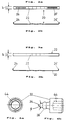
- Fig. 1 shows an example of a door handle connection with two door handles 10 and 10 ', which are connected to their handle necks 12 and 12' by means of a square connecting pin 14.
- a fastening screw 30 is screwed into a radial threaded hole 32 of each handle neck 12 or 12 ', which can be provided with a cone tip 34 as well as a thickening or a bead 36 and an internal hexagon 44 (FIG. 4b).
- a leaf spring 20 is arranged on a side surface 16 of the square pin 14, for which different embodiments come into consideration.
- 2a and 2b show a leaf spring 20 with a central corrugation area 22 and angled ends 24, 24 '. Towards these ends, longitudinal slots 26, 26 'are preferably provided which are missing in the embodiment of FIGS. 3 and 3b.
- the leaf spring 20 shown there has basically the same structure, but without openings.
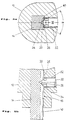
- the cone tip 34 of the fastening screw 30 has a specific cone opening angle ⁇ . This is preferably slightly smaller than a wedge angle of the longitudinal groove 40, which extends over the entire length of the connecting pin 14. If the screw 30 is now screwed into the radial threaded hole 32 of the handle neck 12, the conical tip 34 and then also the thickening 36 first penetrates the leaf spring 20, which can have a suitable longitudinal slot 26 (FIG. 5b). In the longitudinal groove 40, the cone tip 34 is guided centrally into the groove base (FIG. 5a), into which it is pressed when it is screwed in further (FIG. 5b).
- FIGS. 6a and 6b show that the square pin 14 has a flat groove 18 on one side surface 16 in order to receive the leaf spring 20 (FIGS. 2a, 2b and 3a, 3b). Their angled end 24 (or 24 ') engages in an associated blind hole 28 (or 28') near the ends of the connecting pin 14.
- the depth t of the shallow groove 18 is dimensioned such that the material thickness of the leaf spring 20 can be accommodated therein.
- Its width b is essentially as large as that Diameter d of the blind hole 28 (FIG. 6b), but shoulders 42 at which the inserted leaf spring 20 is supported can be present at the blind hole entrance with a slightly larger width.
- FIG. 7 A modified embodiment is shown in FIG. 7, wherein a handle neck 12 made of plastic is penetrated by a fastening screw 30, which is designed as a self-tapping screw and penetrates the leaf spring 20 in the region of the longitudinal slot 26 with the lower thread edge.
- the end of the screw shaft 38 is pressed into the base of the longitudinal groove 40 when the fastening screw 30 is fully screwed in, so that the square pin 14 is fixed axially.
- the longitudinal groove 40 can also deviate from the drawn contour, but preferably with adaptation to the shape of the press-in tip of the fastening screw 30. If this has a thickening or a bulge 26, this can also have a different shape, for example with at least one an undercut.
- the invention further contemplates slightly displacing the longitudinal slots 26, 26 'and the center of the longitudinal groove 40 in order to achieve an additional wedge effect.
- the diameter d of the blind holes 28, 28 'in the square pin 14 can also be smaller, but expediently such that the constricted ends 24, 24' of the leaf spring 20 are held in a snug or clamped fit.
- the corrugation 22 of the leaf spring 20 is preferably chosen so that the latter is held with a slight preload between the one side surface 16 and the square holes of the handle necks 12, 12 'or the lock nut.
Landscapes
- Engineering & Computer Science (AREA)
- Mechanical Engineering (AREA)
- Lock And Its Accessories (AREA)
- Connection Of Plates (AREA)
- Pivots And Pivotal Connections (AREA)
- Casings For Electric Apparatus (AREA)
- Walking Sticks, Umbrellas, And Fans (AREA)
- Dry Shavers And Clippers (AREA)
Priority Applications (1)
| Application Number | Priority Date | Filing Date | Title |
|---|---|---|---|
| AT90121396T ATE101228T1 (de) | 1990-01-08 | 1990-11-08 | Tuergriffverbindung. |
Applications Claiming Priority (2)
| Application Number | Priority Date | Filing Date | Title |
|---|---|---|---|
| DE9000103U DE9000103U1 (da) | 1990-01-08 | 1990-01-08 | |
| DE9000103U | 1990-01-08 |
Publications (3)
| Publication Number | Publication Date |
|---|---|
| EP0436795A2 EP0436795A2 (de) | 1991-07-17 |
| EP0436795A3 EP0436795A3 (en) | 1991-09-25 |
| EP0436795B1 true EP0436795B1 (de) | 1994-02-02 |
Family
ID=6849837
Family Applications (1)
| Application Number | Title | Priority Date | Filing Date |
|---|---|---|---|
| EP90121396A Expired - Lifetime EP0436795B1 (de) | 1990-01-08 | 1990-11-08 | Türgriffverbindung |
Country Status (3)
| Country | Link |
|---|---|
| EP (1) | EP0436795B1 (da) |
| AT (1) | ATE101228T1 (da) |
| DE (2) | DE9000103U1 (da) |
Cited By (3)
| Publication number | Priority date | Publication date | Assignee | Title |
|---|---|---|---|---|
| DE202005000785U1 (de) * | 2005-01-17 | 2006-05-24 | Hoppe Ag, St Martin | Betätigungshandhabe |
| EP1683933A2 (de) | 2005-01-17 | 2006-07-26 | Hoppe AG | Betätigungshandhabe |
| EP2172606B2 (de) † | 2008-10-06 | 2019-04-03 | Burg-Wächter Kg | Drückeranordnung |
Families Citing this family (2)
| Publication number | Priority date | Publication date | Assignee | Title |
|---|---|---|---|---|
| DE29910741U1 (de) * | 1999-06-19 | 1999-09-23 | Hoppe Ag St Martin | Stiftverbindung |
| FR2820775B1 (fr) * | 2001-02-14 | 2003-09-12 | Jean Louis Rousseaux | Insert de pied de bequille pour poignee et poignee comportant un tel insert |
Family Cites Families (4)
| Publication number | Priority date | Publication date | Assignee | Title |
|---|---|---|---|---|
| DE1653967B1 (de) * | 1967-04-25 | 1971-04-22 | Engstfeld Wilh Fa | Druecker-Dornverbindung |
| FR2076269A5 (da) * | 1970-01-07 | 1971-10-15 | Lauzier Rene | |
| DE2024652A1 (de) * | 1970-05-21 | 1971-12-09 | Heinrich Romberg Baubeschlag- und Metallwarenfabrik, 5860 Iserlohn | Türdrückerverbindung |
| DE8605427U1 (da) * | 1986-02-28 | 1986-12-11 | Hoppe Gmbh & Co Kg, 3570 Stadtallendorf, De |
-
1990
- 1990-01-08 DE DE9000103U patent/DE9000103U1/de not_active Expired - Lifetime
- 1990-11-08 EP EP90121396A patent/EP0436795B1/de not_active Expired - Lifetime
- 1990-11-08 AT AT90121396T patent/ATE101228T1/de not_active IP Right Cessation
- 1990-11-08 DE DE90121396T patent/DE59004516D1/de not_active Expired - Lifetime
Cited By (4)
| Publication number | Priority date | Publication date | Assignee | Title |
|---|---|---|---|---|
| DE202005000785U1 (de) * | 2005-01-17 | 2006-05-24 | Hoppe Ag, St Martin | Betätigungshandhabe |
| EP1683933A2 (de) | 2005-01-17 | 2006-07-26 | Hoppe AG | Betätigungshandhabe |
| US7686357B2 (en) | 2005-01-17 | 2010-03-30 | Hoppe Ag | Operating mechanism |
| EP2172606B2 (de) † | 2008-10-06 | 2019-04-03 | Burg-Wächter Kg | Drückeranordnung |
Also Published As
| Publication number | Publication date |
|---|---|
| ATE101228T1 (de) | 1994-02-15 |
| EP0436795A2 (de) | 1991-07-17 |
| EP0436795A3 (en) | 1991-09-25 |
| DE9000103U1 (da) | 1990-02-22 |
| DE59004516D1 (de) | 1994-03-17 |
Similar Documents
| Publication | Publication Date | Title |
|---|---|---|
| EP0662200B1 (de) | Vorrichtung zum verbinden von wenigstens zwei elementen | |
| DE4330102C2 (de) | Verbindungselement | |
| EP0136431A2 (de) | Konstruktion aus Profilstäben | |
| DE2610200C3 (de) | Beschlag zum lösbaren Verbinden zweier Bauteile, insbesondere von plattenförmigen Bauteilen für Möbel | |
| EP3124734A1 (de) | Verbindungsanordnung zum verbinden eines pfostens an einem rahmenprofil eines fensters oder einer türe aus kunststoff | |
| DE10146492B4 (de) | Verbindungselement für Profile | |
| EP3656252B1 (de) | Stuhl | |
| EP0539687B1 (de) | Querverbindung für Profilstäbe mit hinterschnittenen Längsnuten | |
| EP0004374B1 (de) | Vorrichtung zum Verbinden von zwei Profilstäben | |
| EP0436795B1 (de) | Türgriffverbindung | |
| DE10112035B4 (de) | Schutzzaun | |
| WO2005073568A1 (de) | Verbindungsvorrichtung für zwei strangartige hohlprofile und verfahren zu deren herstellung | |
| EP0423474B1 (de) | Vorrichtung zum lösbaren Verbinden von zwei Profilstäben | |
| EP0731282A1 (de) | Befestigungselement | |
| EP1116457A1 (de) | Konstruktionssystem für Gestelle, Möbel oder dergleichen | |
| DE2222717A1 (de) | Einrichtung zum befestigen eines tuerschildes oder einer tuerrosette | |
| EP0791759A1 (de) | Schnellverschluss | |
| CH482929A (de) | Verankerungsvorrichtung zum lösbaren Befestigen von Gegenständen an einer Hohlprofilschiene | |
| EP0235385B1 (de) | Türgriffverbindung | |
| EP0984173A2 (de) | Montageelement zur Positionierung und Verbindung von beabstandeten Bauteilen und Verbindungsstellen unter Verwendung des Montageelements | |
| DE4316808C2 (de) | Spannstück für Rohrelemente | |
| DE4339042C1 (de) | Vorrichtung zur Befestigung eines Bauteils an einem Verbindungsstift | |
| EP1335138B1 (de) | Profilstabverbinder | |
| EP0291973B1 (de) | Verbindungsstück für zwei winklig aneinanderstossende Profilstäbe von Fenster oder Türrahmen | |
| EP1114905A1 (de) | Montagehülse |
Legal Events
| Date | Code | Title | Description |
|---|---|---|---|
| PUAI | Public reference made under article 153(3) epc to a published international application that has entered the european phase |
Free format text: ORIGINAL CODE: 0009012 |
|
| 17P | Request for examination filed |
Effective date: 19901217 |
|
| AK | Designated contracting states |
Kind code of ref document: A2 Designated state(s): AT BE CH DE FR GB IT LI NL |
|
| PUAL | Search report despatched |
Free format text: ORIGINAL CODE: 0009013 |
|
| AK | Designated contracting states |
Kind code of ref document: A3 Designated state(s): AT BE CH DE FR GB IT LI NL |
|
| 17Q | First examination report despatched |
Effective date: 19921106 |
|
| GRAA | (expected) grant |
Free format text: ORIGINAL CODE: 0009210 |
|
| AK | Designated contracting states |
Kind code of ref document: B1 Designated state(s): AT BE CH DE FR GB IT LI NL |
|
| REF | Corresponds to: |
Ref document number: 101228 Country of ref document: AT Date of ref document: 19940215 Kind code of ref document: T |
|
| REF | Corresponds to: |
Ref document number: 59004516 Country of ref document: DE Date of ref document: 19940317 |
|
| ET | Fr: translation filed | ||
| GBT | Gb: translation of ep patent filed (gb section 77(6)(a)/1977) |
Effective date: 19940317 |
|
| ITF | It: translation for a ep patent filed |
Owner name: STUDIO JAUMANN |
|
| PLBE | No opposition filed within time limit |
Free format text: ORIGINAL CODE: 0009261 |
|
| STAA | Information on the status of an ep patent application or granted ep patent |
Free format text: STATUS: NO OPPOSITION FILED WITHIN TIME LIMIT |
|
| 26N | No opposition filed | ||
| REG | Reference to a national code |
Ref country code: GB Ref legal event code: IF02 |
|
| PGFP | Annual fee paid to national office [announced via postgrant information from national office to epo] |
Ref country code: DE Payment date: 20091120 Year of fee payment: 20 Ref country code: CH Payment date: 20091124 Year of fee payment: 20 Ref country code: AT Payment date: 20091113 Year of fee payment: 20 |
|
| PGFP | Annual fee paid to national office [announced via postgrant information from national office to epo] |
Ref country code: NL Payment date: 20091112 Year of fee payment: 20 |
|
| PGFP | Annual fee paid to national office [announced via postgrant information from national office to epo] |
Ref country code: IT Payment date: 20091126 Year of fee payment: 20 Ref country code: GB Payment date: 20091119 Year of fee payment: 20 Ref country code: FR Payment date: 20091201 Year of fee payment: 20 |
|
| PGFP | Annual fee paid to national office [announced via postgrant information from national office to epo] |
Ref country code: BE Payment date: 20091224 Year of fee payment: 20 |
|
| REG | Reference to a national code |
Ref country code: CH Ref legal event code: PL |
|
| REG | Reference to a national code |
Ref country code: NL Ref legal event code: V4 Effective date: 20101108 |
|
| BE20 | Be: patent expired |
Owner name: *HOPPE G.M.B.H. + CO. K.G. Effective date: 20101108 |
|
| REG | Reference to a national code |
Ref country code: GB Ref legal event code: PE20 Expiry date: 20101107 |
|
| PG25 | Lapsed in a contracting state [announced via postgrant information from national office to epo] |
Ref country code: NL Free format text: LAPSE BECAUSE OF EXPIRATION OF PROTECTION Effective date: 20101108 |
|
| PG25 | Lapsed in a contracting state [announced via postgrant information from national office to epo] |
Ref country code: GB Free format text: LAPSE BECAUSE OF EXPIRATION OF PROTECTION Effective date: 20101107 |
|
| PG25 | Lapsed in a contracting state [announced via postgrant information from national office to epo] |
Ref country code: DE Free format text: LAPSE BECAUSE OF EXPIRATION OF PROTECTION Effective date: 20101108 |