EP0436396A2 - Speed indicator - Google Patents
Speed indicator Download PDFInfo
- Publication number
- EP0436396A2 EP0436396A2 EP90314374A EP90314374A EP0436396A2 EP 0436396 A2 EP0436396 A2 EP 0436396A2 EP 90314374 A EP90314374 A EP 90314374A EP 90314374 A EP90314374 A EP 90314374A EP 0436396 A2 EP0436396 A2 EP 0436396A2
- Authority
- EP
- European Patent Office
- Prior art keywords
- speed
- vehicle
- vehicle speed
- display unit
- speed indicator
- Prior art date
- Legal status (The legal status is an assumption and is not a legal conclusion. Google has not performed a legal analysis and makes no representation as to the accuracy of the status listed.)
- Withdrawn
Links
Images

Classifications
-
- B—PERFORMING OPERATIONS; TRANSPORTING
- B60—VEHICLES IN GENERAL
- B60Q—ARRANGEMENT OF SIGNALLING OR LIGHTING DEVICES, THE MOUNTING OR SUPPORTING THEREOF OR CIRCUITS THEREFOR, FOR VEHICLES IN GENERAL
- B60Q1/00—Arrangement of optical signalling or lighting devices, the mounting or supporting thereof or circuits therefor
- B60Q1/26—Arrangement of optical signalling or lighting devices, the mounting or supporting thereof or circuits therefor the devices being primarily intended to indicate the vehicle, or parts thereof, or to give signals, to other traffic
- B60Q1/50—Arrangement of optical signalling or lighting devices, the mounting or supporting thereof or circuits therefor the devices being primarily intended to indicate the vehicle, or parts thereof, or to give signals, to other traffic for indicating other intentions or conditions, e.g. request for waiting or overtaking
- B60Q1/54—Arrangement of optical signalling or lighting devices, the mounting or supporting thereof or circuits therefor the devices being primarily intended to indicate the vehicle, or parts thereof, or to give signals, to other traffic for indicating other intentions or conditions, e.g. request for waiting or overtaking for indicating speed outside of the vehicle
-
- G—PHYSICS
- G01—MEASURING; TESTING
- G01P—MEASURING LINEAR OR ANGULAR SPEED, ACCELERATION, DECELERATION, OR SHOCK; INDICATING PRESENCE, ABSENCE, OR DIRECTION, OF MOVEMENT
- G01P1/00—Details of instruments
- G01P1/04—Special adaptations of driving means
-
- G—PHYSICS
- G01—MEASURING; TESTING
- G01P—MEASURING LINEAR OR ANGULAR SPEED, ACCELERATION, DECELERATION, OR SHOCK; INDICATING PRESENCE, ABSENCE, OR DIRECTION, OF MOVEMENT
- G01P1/00—Details of instruments
- G01P1/07—Indicating devices, e.g. for remote indication
- G01P1/08—Arrangements of scales, pointers, lamps or acoustic indicators, e.g. in automobile speedometers
Definitions
- This invention relates to speed indicators and in particular to indicators for vehicles.
- Vehicles are subject of various speed restrictions according to the kind of road on which the vehicle is travelling and on the location of the road. In addition different vehicles have different maximum speed restrictions imposed on them.
- An object of the invention is to provide means whereby there is an external indication of the speeds of vehicles to assist in the maintenance of vehicle speeds within the allowed limits.
- a vehicle speed indicator comprises a speed display unit mounted in a vehicle to be visible to following vehicles, and vehicle speed detection means for detecting the speed of the associated vehicle and for generating a signal according to such speed, the signal being passed to the display unit which is arranged to display the vehicle speed rearwardly of the vehicle.
- the speed display unit is mounted internally on the rear windscreen of the vehicle and includes means for changing the speed which is displayed in the form of numbers.
- the unit includes a LED display which is controlled according to the signals from the speed detection means.
- the size of the LED display is selected to be visible from a distance by the drivers of following vehicles, for example the numbers may be of the size of the letters and numbers of a vehicle number plate and visible at 25 metres or more.
- the speed detection means may detect the vehicle speed in any convenient manner.
- a speed indicating signal is generated by a sensor associated with the vehicle's conventional speed indicator.
- the sensor may be arranged to sense the rotation of the speedometer cable or an associated rotating element, or the sensor may include a tachogenerator directly driven from the speedometer cable.
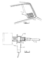
- a speed display device 10 is shown mounted on the rear windscreen of a passenger car vehicle so that the device is readily visible to following vehicles.
- the device includes a LED display 11 the numbers on which can be constantly varied according to the speed at which the vehicle is travelling.
- the display may be of any convenient kind which is capable of displaying numbers of a size visible to the following vehicles when travelling at a safe distance behind the displaying vehicle.
- the device may be positioned at any convenient location on the windscreen such that rearward vision of the vehicle driver is not adversely affected.
- the speed range may be between 10 and 120 mph.
- the numbers change colour when excessive speeds are reached.
- the colour may be green up to 70 mph and red when above 70 mph.
- the device 10 is connected to a speed detector such as shown in Fig. 2 or Fig. 3, the detector in each case generating a signal corresponding to the speed of the vehicle and transmitting the signal to the device 10.
- the speed detector is associated with the cable 13 which conventionally transmits the vehicle speed to a dashboard mounted speedometer 14.
- a housing 15 is provided interposed between the end of the cable and the speedometer and in the housing is located a rotary member 16 drivingly connected to the cable 13 at one end and to the speedometer 14 at the other end.
- a sensor 17 which in known manner detects the rotation of the rotary member 16 is located adjacent the member 16 and generates a signal dependent on the speed of rotation for transmission to the speed display device 10.
- a gearwheel 20 is interposed between the cable 13 and the speedometer in a housing 21.
- the gearwheel 20 drives a further gearwheel 22 which in turn drives a tachogenerator 23.
- the tachogenerator 23 may take any convenient form and produces an electrical signal corresponding to the speed of the vehicle. The signal produced is transmitted to the device 10 for display.
- the speed indicator can be fitted to any vehicle either when the vehicle is manufactured or as a later fitting. It warns following vehicles of the speed at which they are travelling and also of the rate of increase of speed of the vehicle carrying the display which is a useful aid when an overtaking manoeuvre is taking place.
- the device would normally be fitted to deter others from driving too fast.
Abstract
Description
- This invention relates to speed indicators and in particular to indicators for vehicles.
- Vehicles are subject of various speed restrictions according to the kind of road on which the vehicle is travelling and on the location of the road. In addition different vehicles have different maximum speed restrictions imposed on them.
- Although speed restrictions are imposed by law many vehicle drivers do not always abide by the restrictions and travel at speeds above those allowed.
- An object of the invention is to provide means whereby there is an external indication of the speeds of vehicles to assist in the maintenance of vehicle speeds within the allowed limits.
- According to the invention a vehicle speed indicator comprises a speed display unit mounted in a vehicle to be visible to following vehicles, and vehicle speed detection means for detecting the speed of the associated vehicle and for generating a signal according to such speed, the signal being passed to the display unit which is arranged to display the vehicle speed rearwardly of the vehicle.
- Preferably the speed display unit is mounted internally on the rear windscreen of the vehicle and includes means for changing the speed which is displayed in the form of numbers. Conveniently the unit includes a LED display which is controlled according to the signals from the speed detection means. The size of the LED display is selected to be visible from a distance by the drivers of following vehicles, for example the numbers may be of the size of the letters and numbers of a vehicle number plate and visible at 25 metres or more.
- The speed detection means may detect the vehicle speed in any convenient manner. In one arrangement a speed indicating signal is generated by a sensor associated with the vehicle's conventional speed indicator. The sensor may be arranged to sense the rotation of the speedometer cable or an associated rotating element, or the sensor may include a tachogenerator directly driven from the speedometer cable.
- Further features of the invention will appear from the following description of an embodiment of the invention given by way of example only and with reference to the drawings, in which:
- Fig. 1 is a perspective view of a speed display unit,
- Fig. 2 is a section through one form of speed detector, and
- Fig. 3 is a section through an alternative form of speed detector.
- Referring to Fig. 1 a
speed display device 10 is shown mounted on the rear windscreen of a passenger car vehicle so that the device is readily visible to following vehicles. - The device includes a
LED display 11 the numbers on which can be constantly varied according to the speed at which the vehicle is travelling. The display may be of any convenient kind which is capable of displaying numbers of a size visible to the following vehicles when travelling at a safe distance behind the displaying vehicle. - The device may be positioned at any convenient location on the windscreen such that rearward vision of the vehicle driver is not adversely affected.
- Other means for displaying the speed may be used and the range of numbers which may be displayed is conveniently between the lower speed limits and a maximum speed attainable by the vehicle. For example in Great Britain the speed range may be between 10 and 120 mph. In one arrangement the numbers change colour when excessive speeds are reached. Thus the colour may be green up to 70 mph and red when above 70 mph.
- The
device 10 is connected to a speed detector such as shown in Fig. 2 or Fig. 3, the detector in each case generating a signal corresponding to the speed of the vehicle and transmitting the signal to thedevice 10. - Referring to Fig. 2 the speed detector is associated with the
cable 13 which conventionally transmits the vehicle speed to a dashboard mountedspeedometer 14. In this case ahousing 15 is provided interposed between the end of the cable and the speedometer and in the housing is located arotary member 16 drivingly connected to thecable 13 at one end and to thespeedometer 14 at the other end. - A
sensor 17 which in known manner detects the rotation of therotary member 16 is located adjacent themember 16 and generates a signal dependent on the speed of rotation for transmission to thespeed display device 10. - Referring now to Fig. 3 there is shown an alternative arrangement including the
cable 13 andspeedometer 14 of Fig. 2 but in this case agearwheel 20 is interposed between thecable 13 and the speedometer in ahousing 21. Thegearwheel 20 drives afurther gearwheel 22 which in turn drives atachogenerator 23. - The
tachogenerator 23 may take any convenient form and produces an electrical signal corresponding to the speed of the vehicle. The signal produced is transmitted to thedevice 10 for display. - The speed indicator can be fitted to any vehicle either when the vehicle is manufactured or as a later fitting. It warns following vehicles of the speed at which they are travelling and also of the rate of increase of speed of the vehicle carrying the display which is a useful aid when an overtaking manoeuvre is taking place. The device would normally be fitted to deter others from driving too fast.
Claims (8)
- Vehicle speed indicator characterised by a speed display unit (10) to be mounted in the vehicle to be visible to following vehicles, and vehicle speed detection means (15, 16, 17) for detecting the speed of the associated vehicle and for generating a signal according to this speed, the signal being passed to the display unit (10) which is arranged to display the vehicle speed rearwardly of the vehicle.
- Vehicle speed indicator according to Claim 1 characterised in that the speed display unit 10 is arranged to be mounted internally on the rear windscreen of the associated vehicle.
- Vehicle speed indicator according to Claim 1 or 2 characterised by means for displaying the speed of the vehicle according to the signal received from the vehicle speed detection means (15, 16, 17).
- A vehicle speed indicator according to Claim 1, 2 or 3 characterised in that the speed display unit (10) includes a LED display 11 controlled according to the signals received from the speed detection means (15, 16, 17).
- A vehicle speed indicator according to any one of the preceding claims characterised in that the speed of the associated vehicle is displayed in numerals which are of a size selected to be readable at a distance of 25 metres or more.
- A vehicle speed indicator according to any one of the preceding claims characterised in that the speed detection means includes a sensor (17) associated with the vehicle's conventional speed indicator (13, 14), which sensor generates a signal according to the vehicle speed.
- A vehicle speed indicator according to Claim 6 characterised in that the sensor (17) is arranged to sense the speed of rotation of the speedometer cable (13) or an associated rotating element.
- A vehicle speed indicator according to Claim 6 characterised in that the sensor includes a tachogenerator (23) driven from the speedometer cable (13).
Applications Claiming Priority (2)
| Application Number | Priority Date | Filing Date | Title |
|---|---|---|---|
| GB8929362 | 1989-12-30 | ||
| GB8929362A GB2239521A (en) | 1989-12-30 | 1989-12-30 | Speed indicator |
Publications (2)
| Publication Number | Publication Date |
|---|---|
| EP0436396A2 true EP0436396A2 (en) | 1991-07-10 |
| EP0436396A3 EP0436396A3 (en) | 1991-10-30 |
Family
ID=10668600
Family Applications (1)
| Application Number | Title | Priority Date | Filing Date |
|---|---|---|---|
| EP19900314374 Withdrawn EP0436396A3 (en) | 1989-12-30 | 1990-12-28 | Speed indicator |
Country Status (2)
| Country | Link |
|---|---|
| EP (1) | EP0436396A3 (en) |
| GB (1) | GB2239521A (en) |
Cited By (3)
| Publication number | Priority date | Publication date | Assignee | Title |
|---|---|---|---|---|
| EP0997344A3 (en) * | 1998-10-28 | 2002-01-23 | Pierluigi Antonelli | A device displaying the speed of a vehicle, moment by moment, in such a manner as to be visible from the outside |
| EP1332917A1 (en) * | 2002-01-31 | 2003-08-06 | Kadeb | Vehicle comprising speed indication means |
| WO2018147854A1 (en) * | 2017-02-09 | 2018-08-16 | Ford Global Technologies, Llc | Display for rear lamp of a vehicle |
Families Citing this family (4)
| Publication number | Priority date | Publication date | Assignee | Title |
|---|---|---|---|---|
| GB2283821B (en) * | 1993-11-15 | 1997-03-05 | Kenneth Cyril Gething | Improvements in signalling apparatus for road vehicles |
| GB2357580A (en) * | 1999-12-16 | 2001-06-27 | Michael Richard Williams | Combined vehicle brake/stop light and speedometer unit |
| GB2372323A (en) * | 2001-02-14 | 2002-08-21 | Ronald Bartlett | Externally visible vehicle speed indicator |
| GB2457450A (en) * | 2008-02-12 | 2009-08-19 | Francis Robson Zvoma | Speed reminding unit to indicate the speed limit to a person driving behind |
Citations (3)
| Publication number | Priority date | Publication date | Assignee | Title |
|---|---|---|---|---|
| DE2256411A1 (en) * | 1972-11-17 | 1974-05-22 | A M Zimmermann & Co | IGNALIZING SPEED MONITOR FOR VEHICLES |
| NL8300073A (en) * | 1983-01-10 | 1984-08-01 | Arjeh Tal | Speed indicators for motor vehicle - are installed on windscreen and rear window as aid to other drivers |
| DE3830667A1 (en) * | 1988-09-09 | 1990-03-15 | Schmidt Ernst Guenther Dipl Ph | External speed indicator for a motor vehicle |
Family Cites Families (6)
| Publication number | Priority date | Publication date | Assignee | Title |
|---|---|---|---|---|
| GB280117A (en) * | 1927-05-21 | 1927-11-10 | Martin Rietz | Improvements in speed indicators for automobiles and the like |
| GB473920A (en) * | 1935-07-22 | 1937-10-22 | Ethelred Harold Chandler | Improvements in speed indicators for motor-road vehicles |
| GB1177969A (en) * | 1967-05-16 | 1970-01-14 | Mary Theresa Hanner | Vehicle Control Light System |
| JPS5764166A (en) * | 1980-10-07 | 1982-04-19 | Stanley Electric Co Ltd | Speed alarming device for automobile |
| GB8416404D0 (en) * | 1984-06-28 | 1984-08-01 | Sepehr F | Speed limit indicator |
| DE3543163A1 (en) * | 1985-12-06 | 1987-06-11 | Mannesmann Kienzle Gmbh | SPEED LIMITER |
-
1989
- 1989-12-30 GB GB8929362A patent/GB2239521A/en not_active Withdrawn
-
1990
- 1990-12-28 EP EP19900314374 patent/EP0436396A3/en not_active Withdrawn
Patent Citations (3)
| Publication number | Priority date | Publication date | Assignee | Title |
|---|---|---|---|---|
| DE2256411A1 (en) * | 1972-11-17 | 1974-05-22 | A M Zimmermann & Co | IGNALIZING SPEED MONITOR FOR VEHICLES |
| NL8300073A (en) * | 1983-01-10 | 1984-08-01 | Arjeh Tal | Speed indicators for motor vehicle - are installed on windscreen and rear window as aid to other drivers |
| DE3830667A1 (en) * | 1988-09-09 | 1990-03-15 | Schmidt Ernst Guenther Dipl Ph | External speed indicator for a motor vehicle |
Cited By (3)
| Publication number | Priority date | Publication date | Assignee | Title |
|---|---|---|---|---|
| EP0997344A3 (en) * | 1998-10-28 | 2002-01-23 | Pierluigi Antonelli | A device displaying the speed of a vehicle, moment by moment, in such a manner as to be visible from the outside |
| EP1332917A1 (en) * | 2002-01-31 | 2003-08-06 | Kadeb | Vehicle comprising speed indication means |
| WO2018147854A1 (en) * | 2017-02-09 | 2018-08-16 | Ford Global Technologies, Llc | Display for rear lamp of a vehicle |
Also Published As
| Publication number | Publication date |
|---|---|
| GB8929362D0 (en) | 1990-02-28 |
| EP0436396A3 (en) | 1991-10-30 |
| GB2239521A (en) | 1991-07-03 |
Similar Documents
| Publication | Publication Date | Title |
|---|---|---|
| US4588267A (en) | Combination rear view mirror and digital clock | |
| USRE32576E (en) | Combination rear view mirror and digital clock | |
| US3691525A (en) | Vehicle speed indicator system | |
| EP0872741A3 (en) | Alarm apparatus for alarming driver of vehicle and method of alarming | |
| CN1297406A (en) | Method for integrated representation of parameters of distance control device | |
| EP0436396A2 (en) | Speed indicator | |
| US6600409B2 (en) | Signaling self-contained add-on accessory for an analog metering device such as a speedometer and secondary device | |
| EP1702799A1 (en) | Speed awareness system | |
| GB2105847A (en) | Vehicle mirror | |
| WO2001048726A1 (en) | Following distance warning system for a vehicle | |
| EP0997344A2 (en) | A device displaying the speed of a vehicle, moment by moment, in such a manner as to be visible from the outside | |
| JPS61175138A (en) | Indicator in automobile | |
| GB2229532A (en) | Vehicle deceleration indicator system | |
| EP3789738A1 (en) | Speedometer display | |
| GB2205698A (en) | Vehicle warning system | |
| KR200395097Y1 (en) | Apparatus warning to restricted speed of vehicle | |
| US20070139927A1 (en) | Parametric display system for motor vehicles | |
| EP0169291A1 (en) | An external speed display device for motor vehicles | |
| KR100252229B1 (en) | Velocity detecting device | |
| JPH09329465A (en) | Display device for vehicle | |
| EP1271447A3 (en) | Device to display an excessive speed | |
| CA1233648A (en) | Combination rear view mirror and digital clock | |
| US3534705A (en) | Motor vehicle speed display device | |
| JPS5940718Y2 (en) | Automotive safe driving level determination device | |
| KR20030034474A (en) | Method for driving speedometer using CAN message |
Legal Events
| Date | Code | Title | Description |
|---|---|---|---|
| PUAI | Public reference made under article 153(3) epc to a published international application that has entered the european phase |
Free format text: ORIGINAL CODE: 0009012 |
|
| AK | Designated contracting states |
Kind code of ref document: A2 Designated state(s): AT BE CH DE DK ES FR GR IT LI LU NL SE |
|
| PUAL | Search report despatched |
Free format text: ORIGINAL CODE: 0009013 |
|
| AK | Designated contracting states |
Kind code of ref document: A3 Designated state(s): AT BE CH DE DK ES FR GR IT LI LU NL SE |
|
| RBV | Designated contracting states (corrected) |
Designated state(s): DE DK ES FR IT SE |
|
| STAA | Information on the status of an ep patent application or granted ep patent |
Free format text: STATUS: THE APPLICATION IS DEEMED TO BE WITHDRAWN |
|
| 18D | Application deemed to be withdrawn |
Effective date: 19920501 |