EP0433840B1 - Kraftfahrzeug-Scheinwerfer - Google Patents
Kraftfahrzeug-Scheinwerfer Download PDFInfo
- Publication number
- EP0433840B1 EP0433840B1 EP90123757A EP90123757A EP0433840B1 EP 0433840 B1 EP0433840 B1 EP 0433840B1 EP 90123757 A EP90123757 A EP 90123757A EP 90123757 A EP90123757 A EP 90123757A EP 0433840 B1 EP0433840 B1 EP 0433840B1
- Authority
- EP
- European Patent Office
- Prior art keywords
- light source
- penetrated
- cover
- motor vehicle
- cover plate
- Prior art date
- Legal status (The legal status is an assumption and is not a legal conclusion. Google has not performed a legal analysis and makes no representation as to the accuracy of the status listed.)
- Expired - Lifetime
Links
- 239000011521 glass Substances 0.000 claims description 19
- 229920003023 plastic Polymers 0.000 claims description 16
- 239000004033 plastic Substances 0.000 claims description 13
- 239000011248 coating agent Substances 0.000 claims description 6
- 238000000576 coating method Methods 0.000 claims description 6
- 239000002184 metal Substances 0.000 claims description 6
- 239000000463 material Substances 0.000 claims description 3
- 230000005855 radiation Effects 0.000 description 36
- 238000009413 insulation Methods 0.000 description 3
- 238000004519 manufacturing process Methods 0.000 description 3
- 230000002411 adverse Effects 0.000 description 1
- 230000005540 biological transmission Effects 0.000 description 1
- 238000010276 construction Methods 0.000 description 1
- 230000000694 effects Effects 0.000 description 1
- 230000005670 electromagnetic radiation Effects 0.000 description 1
- 229910052736 halogen Inorganic materials 0.000 description 1
- 150000002367 halogens Chemical class 0.000 description 1
- 238000001228 spectrum Methods 0.000 description 1
- 239000013585 weight reducing agent Substances 0.000 description 1
Images

Classifications
-
- F—MECHANICAL ENGINEERING; LIGHTING; HEATING; WEAPONS; BLASTING
- F21—LIGHTING
- F21S—NON-PORTABLE LIGHTING DEVICES; SYSTEMS THEREOF; VEHICLE LIGHTING DEVICES SPECIALLY ADAPTED FOR VEHICLE EXTERIORS
- F21S41/00—Illuminating devices specially adapted for vehicle exteriors, e.g. headlamps
- F21S41/20—Illuminating devices specially adapted for vehicle exteriors, e.g. headlamps characterised by refractors, transparent cover plates, light guides or filters
- F21S41/28—Cover glass
Definitions
- the invention relates to a motor vehicle headlight according to the preamble of patent claim 1.
- Such a motor vehicle operating on the projection principle is known, for example, from DE-A 3640773.
- the cover plate is made of glass, since glass has good light transmission and high scratch resistance.
- the disadvantage of glass as a manufacturing material for the cover plate is its high specific weight. Due to the high specific weight of glass, the cover plate has a significant proportion of the total weight of the motor vehicle headlight in relation to the other components of the motor vehicle headlight.
- the known motor vehicle headlight is very heavy overall. It is also known from DE-U 85 35 948 a conventional headlamp that does not work according to the projection principle.
- the glass cover plate has side extensions made of plastic. This covers an additional indicator light, which is arranged adjacent to the headlight.
- the invention has for its object to reduce the overall weight of a motor vehicle headlight of the type mentioned without sacrificing the advantages of a glass cover plate.
- the part of the cover pane penetrated by the radiation from the light source has a share of only about 27% of the entire cover pane in a conventional headlight.
- the remaining 73% of the cover plate is practically ineffective for the light utilization, because apart from a vanishingly small percentage, the radiation from the light source penetrates the 27% share of the cover plate.
- This fact is exploited for a weight reduction measure in that the 73% of the cover plate is made from a plastic that has a significantly lower specific weight than glass. This reduces the weight of the cover plate of the motor vehicle headlight according to the invention compared to the weight of the cover plate of the known motor vehicle headlight and thus the total weight of the motor vehicle headlight according to the invention.
- the motor vehicle headlight according to the invention is light and also has the advantages of a motor vehicle headlight with a cover plate made of glass.
- the construction of the cover plate according to the invention has a further advantage if a high-pressure discharge lamp with low heat radiation is used as the light source.
- the part of the cover pane which is not penetrated by the radiation from the light source is made of a plastic with a significantly lower thermal conductivity than glass. This results in the thermal insulation of the part of the cover pane penetrated by the radiation of the light source from the other components of the headlight. The heat is not dissipated as quickly from the part of the cover pane penetrated by the radiation from the light source as in the case of the cover plate made entirely of glass of the known motor vehicle headlight.
- the heat radiation of a high-pressure discharge lamp which is low compared to, for example, a halogen lamp, is sufficient to heat the part of the cover pane penetrated by the radiation from the light source to such an extent that ice and / or snow can be melted off in the cold season.
- the structural design of the motor vehicle headlamp according to the invention becomes simple if the part of the radiation penetrated by the light source Cover plate is at the same time the projection lens, because then a separate projection lens and thus also a holder for the projection lens in the interior of the motor vehicle headlight, for example by means of a ring diaphragm, are dispensed with. This results in a further reduction in the weight of the motor vehicle headlight according to the invention.
- the part of the cover plate which is not penetrated by the radiation from the light source is made of a transparent plastic, this part can be used as a diffusing plate for the parking light.
- the view through the cover plate into the headlight interior is prevented in the known headlight by a ring-shaped plastic cover, which is arranged around the projection lens.
- the plastic cover can be dispensed with if a metal coating on the side of the cover pane facing the light source does not perform the function of the cover plate, as the radiation from the light source does not penetrate it.
- the metal coating has a further advantage if a high-pressure discharge lamp is used as the light source. The metal coating then additionally largely shields the electromagnetic radiation emitted by the high-pressure discharge lamp in the direction of the cover plate.
- the part of the cover pane penetrated by the radiation from the light source and that by the radiation from the Parts of the cover plate which are not penetrated by light source are immovably connected to one another after the production process of the cover plate according to the invention has ended.
- the part of the cover pane to be produced from plastic and not penetrated by the radiation from the light source can thus be injection-molded in a simple manner onto the abutting surface of the part of the cover pane penetrated by the radiation from the light source.
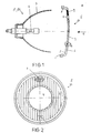
- the motor vehicle headlight 1 shows a schematic illustration of a motor vehicle headlight 1 with a high-pressure discharge lamp 2, which emits radiation that is not shown in the drawing.
- the motor vehicle headlight 1 further comprises a reflector 3, which reflects the radiation from the high-pressure discharge lamp 2.
- the reflected radiation penetrates a part 4 of the cover plate 5 made of glass, which is designed as a projection lens.
- the part 4 of the cover plate 5 penetrated by the radiation of the high-pressure discharge lamp 2 is surrounded by a part 6 made of transparent plastic. (See also FIG. 2)
- the side 7 of the part 6 of the cover plate 5 which is not penetrated by the radiation from the high-pressure discharge lamp 2 and faces the high-pressure discharge lamp 2 is partially provided with a metal coating 8.
- the area 9 of the part 6 of the cover plate 5 which is not penetrated by the radiation of the high-pressure discharge lamp 2 and which is not provided with the metal coating 8 serves as a parking light diffusing screen. (see also Fig. 2).
- FIG. 2 shows the cover plate 5 of the motor vehicle headlight from FIG. 1 from viewing direction A.
- FIG. 3 shows the interlocking profiles of the abutting surfaces between the part 4 of the cover plate 5 penetrated by the radiation from the high-pressure discharge lamp 2 (FIG. 1) and the part 6 of the cover plate 5 not penetrated by the radiation from the high-pressure discharge lamp 2 (FIG. 1).
- the part 4 of the cover plate 5 which is penetrated by the radiation from the high-pressure discharge lamp 2 has a share of 27% in the entire cover plate 5.
- the remaining part of 73% is almost ineffective for the use of light, since apart from a vanishingly small percentage, the radiation from the high-pressure discharge lamp 2 passes part 4 of the cover plate 5.
- the remaining 73% of the cover plate 5 is made of a plastic with a significantly lower specific weight than glass.
- the total weight of the cover plate 5 of the motor vehicle headlight according to the invention is significantly less than that of a cover plate made entirely of glass. This results overall in a lower total weight of the motor vehicle headlamp according to the invention compared to the known headlamp.
- the high-pressure discharge lamp 2 When the high-pressure discharge lamp 2 is switched on, the radiation emitted by it with a wide frequency spectrum, not shown in the drawing, strikes part 4 of the cover plate 5 partly directly and partly reflected by the reflector 3. The radiation passes through part 4 of the cover plate 5, which at the same time passes through the projection lens is. Part 4 of the cover plate 5 is heated by the heat radiation contained in the radiation from the high-pressure discharge lamp 2. The low heat radiation from the high-pressure discharge lamp 2 is sufficient to heat part 4 of the cover plate 5 to such an extent that any snow and / or ice layer present on it is melted off.
Landscapes
- Engineering & Computer Science (AREA)
- General Engineering & Computer Science (AREA)
- Non-Portable Lighting Devices Or Systems Thereof (AREA)
Description
- Die Erfindung bezieht sich auf einen Kraftfahrzeug-Scheinwerfer gemäß dem Oberbegriff des Patentanspruchs 1.
- Ein derartiger nach dem Projektionsprinzip arbeitender Kraftfahrzeug ist beispielsweise aus der DE-A 3640773 bekannt. Bei diesem bekannten Kraftfahrzeug-Scheinwerfer ist die Abdeckscheibe aus Glas gefertigt, da Glas eine gute Lichtdurchlässigkeit und eine hohe Kratzfestigkeit ausweist. Der Nachteil von Glas als Fertigungsmaterial für die Abdeckscheibe ist aber sein hohes spezifisches Gewicht. Aufgrund des hohen spezifischen Gewichtes von Glas hat die Abdeckscheibe in Relation zu den übrigen Bauteilen des Kraftfahrzeug-Scheinwerfers einen erheblichen Anteil am Gesamtgewicht des Kraftfahrzeug-Scheinwerfers. Der bekannte Kraftfahrzeug-Scheinwerfer ist insgesamt sehr schwer. Es ist ferner aus der DE-U 85 35 948 ein konventioneller, nicht nach dem Projektionsprinzip arbeitender Scheinwerfer bekannt. Dabei besitzt die aus Glas bestehende Abdeckscheibe seitliche Ansätze aus Plastikmaterial. Damit wird eine zusätzliche Anzeigeleuchte, die benachbart zu dem Scheinwerfer angeordnet ist, abgedeckt.
- Der Erfindung liegt die Aufgabe zugrunde, einen Kraftfahrzeug-Scheinwerfer der eingangs genannten Art in seinem Gesamtgewicht zu verringern, ohne auf die Vorteile einer Abdeckscheibe aus Glas zu verzichten.
- Die Aufgabe wird durch die kennzeichnenden Merkmale des Patentanspruchs 1 gelöst.
- Der von der Strahlung der Lichtquelle durchdrungene Teil der Abdeckscheibe hat bei einem üblichen Scheinwerfer einen Anteil von nur etwa 27% an der gesamten Abdeckscheibe. Der verbleibende Anteil von 73% der Abdeckscheibe ist für die Lichtausnutzung so gut wie nicht wirksam, da bis auf einen verschwindend geringen Prozentsatz die Strahlung der Lichtquelle den 27%-Anteil der Abdeckscheibe durchdringt. Diese Tatsache wird für eine Gewichtsreduzierungsmaßnahme ausgenutzt, indem der Anteil von 73% der Abdeckscheibe aus einem Kunststoff gefertigt wird, der gegenüber Glas ein deutlich geringeres spezifisches Gewicht hat. Dadurch verringert sich das Gewicht der Abdeckscheibe des erfindungsgemäßen Kraftfahrzeug-Scheinwerfers gegenüber dem Gewicht der Abdeckscheibe des bekannten Kraftfahrzeug-Scheinwerfers und somit das Gesamtgewicht des erfindungsgemäßen Kraftfahrzeug-Scheinwerfers.
- Kratzer auf der Abdeckscheibe beeinträchtigen die Lichtausnutzung. Glas besitzt gegenüber Kunststoff eine wesentlich höhere Kratzfestigkeit. Da der von der Strahlung der Lichtquelle durchdrungene Teil der Abdeckscheibe aus Glas gefertigt ist, besitzt dieser Teil eine höhere Kratzfestigkeit als der von der Strahlung der Lichtquelle nicht durchdrungene Teil der Abdeckscheibe. Die Gefahr der Lichtbeeinträchtigung durch Kratzer auf dem von der Strahlung der Lichtquelle durchdrungenen Teil der Abdeckscheibe ist somit wesentlich geringer als bei einer vollständig aus Kunststoff gefertigten Abdeckscheibe.
- Der erfindungsgemäße Kraftfahrzeug-Scheinwerfer ist leicht und hat zudem die Vorteile eines Kraftfahrzeug-Scheinwerfers mit einer Abdeckscheibe aus Glas.
- Einen weiteren Vorteil hat der erfindungsgemäße Aufbau der Abdeckscheibe, wenn als Lichtquelle eine Hochdruckentladungslampe mit geringer Wärmestrahlung verwendet wird. Der von der Strahlung der Lichtquelle nicht durchdrungene Teil der Abdeckscheibe ist aus einem Kunststoff mit einer gegenüber Glas wesentlich geringeren Wärmeleitfähigkeit gefertigt. Daraus resultiert die thermische Isolation des von der Strahlung der Lichtquelle durchdrungenen Teils der Abdeckscheibe gegenüber den übrigen Bauteilen des Scheinwerfers. Die Wärme wird nicht so schnell von dem von der Strahlung der Lichtquelle durchdrungenen Teil der Abdeckscheibe abgeleitet wie bei der vollständig aus Glas gefertigten Abdeckscheibe des bekannten Kraftfahrzeug-Scheinwerfers. Dadurch reicht die gegenüber beispielsweise einer Halogenlampe geringe Wärmestrahlung einer Hochdruckentladungslampe aus, um den von der Strahlung der Lichtquelle durchdrungenen Teil der Abdeckscheibe so weit zu erwärmen, daß in der kalten Jahreszeit Eis und/oder Schnee abgeschmolzen werden können.
- Der konstruktive Aufbau des erfindungsgemäßen Kraftfahrzeug-Scheinwerfers wird einfach, wenn der von der Strahlung der Lichtquelle durchdrungene Teil der Abdeckscheibe gleichzeitig die Projektionslinse ist, weil dann eine separate Projektionslinse und damit auch eine Halterung für die Projektionslinse im Kraftfahrzeug-Scheinwerferinneren, z.B. durch eine Ringblende, entfallen. Dies hat eine weitere Verringerung des Gewichtes des erfindungsgemäßen Kraftfahrzeugs-Scheinwerfers zur Folge.
- Wenn der von der Strahlung der Lichtquelle nicht durchdrungene Teil der Abdeckscheibe aus einem transparentem Kunststoff hergestellt ist, läßt sich dieser Teil als Streuscheibe für das Standlicht nützen.
- Die Sicht durch die Abdeckscheibe in das Scheinwerferinnere wird bei dem bekannten Scheinwerfer durch eine ringförmige Kunststoffzierblende, die um die Projektionslinse angeordnet ist, verhindert. Die Kunststoffzierblende kann entfallen, wenn eine Metallbeschichtung auf der der Lichtquelle zugewandten Seite des von der Strahlung der Lichtquelle nicht durchdrungenen Teils der Abdeckscheibe die Funktion der Zierblende übernimmt. Einen weiteren Vorteil bringt die Metallbeschichtung, wenn als Lichtquelle eine Hochdruckentladungslampe dient. Die Metallbeschichtung schirmt dann zusätzlich die von der Hochdruckentladungslampe in Richtung der Abdeckscheibe ausgesandte elektromagnetische Strahlung größtenteils ab.
- Der von der Strahlung der Lichtquelle durchdrungene Teil der Abdeckscheibe und der von der Strahlung der Lichtquelle nicht durchdrungene Teil der Abdeckscheibe sind nach Beendigung des Herstellungsvorgangs der erfindungsgemäßen Abdeckscheibe unverrückbar miteinander verbunden. Dies wird dadurch erreicht, daß die Stoßflächen zwischen dem von der Strahlung der Lichtquelle durchdrungenen Teil und dem von der Strahlung der Lichtquelle nicht durchdrungenen Teil der Abdeckscheibe als ineinander greifende Profile ausgebildet sind. Bei der Herstellung der erfindungsgemäßen Abdeckscheibe kann somit der aus Kunststoff zu fertigende, von der Strahlung der Lichtquelle nicht durchdrungene Teil der Abdeckscheibe in einfacher Weise an die Stoßfläche des von der Strahlung der Lichtquelle durchdrugenen Teils der Abdeckscheibe angespritzt werden.
- Im folgenden wird die Erfindung anhand eines Ausführungsbeipiels näher erläutert. Es zeigen
- Fig. 1
- eine schematische Darstellung eines erfindungsgemäßen Kraftfahrzeug-Scheinwerfers
- Fig. 2
- die Abdeckscheibe des Kraftfahrzeug-Scheinwerfers von Fig. 1. aus Blickrichtung A
- Fig. 3
- eine vergrößerte Darstellung des Ausschnittes B aus Fig. 1.
- Fig 1. zeigt eine schematische Darstellung eines Kraftfahrzeug-Scheinwerfers 1 mit einer Hochdruckentladungslampe 2, die eine in der Zeichnung nicht dargestellte Strahlung abgibt. Der Kraftfahrzeug-Scheinwerfer 1 umfaßt ferner einen Reflektor 3, der die Strahlung der Hochdruckentladungslampe 2 reflektiert. Die reflektierte Strahlung durchdringt einen aus Glas gefertigten Teil 4 der Abdeckscheibe 5, der als Projektionslinse ausgebildet ist. Der von der Strahlung der Hochdruckentladungslampe 2 durchdrungene Teil 4 der Abdeckscheibe 5 ist von einem Teil 6 aus transparentem Kunststoff eingefaßt. ( siehe auch Fig. 2 ) Die der Hochdruckentladungslampe 2 zugewandte Seite 7 des von der Strahlung der Hochdruckentladungslampe 2 nicht durchdrungenen Teils 6 der Abdeckscheibe 5 ist teilweise mit einer Metallbeschichtung 8 versehen. Der nicht mit der Metallbeschichtung 8 versehene Bereich 9 des von der Strahlung der Hochdruckentladungslampe 2 nicht durchdrungenen Teils 6 der Abdeckscheibe 5 dient als Standlichtstreuscheibe. ( siehe auch Fig. 2 ).
- Fig 2 zeigt die Abdeckscheibe 5 des Kraftfahrzeug-Scheinwerfers von Fig. 1 aus Blickrichtung A.
- Fig 3 zeigt die ineinander greifenden Profile der Stoßflächen zwischen dem von der Strahlung der Hochdruckentladungslampe 2 (Fig. 1) durchdrungenen Teil 4 der Abdeckscheibe 5 und dem von der Strahlung der Hochdruckentladungslampe 2 (Fig. 1) nicht durchdrungenen Teil 6 der Abdeckscheibe 5.
- Der von der Strahlung der Hochdruckentladungslampe 2 durchdrungene Teil 4 der Abdeckscheibe 5 hat einen Anteil von 27% an der gesamten Abdeckscheibe 5. Der verbleibende Anteil von 73% ist für die Lichtausnutzung fast nicht wirksam, da bis auf einen verschwindend geringen Prozentsatz die Strahlung der Hochdruckentladungslampe 2 den Teil 4 der Abdeckscheibe 5 passiert. Der verbleibende Anteil von 73% der Abdeckscheibe 5 ist aus einem Kunststoff mit einem gegenüber Glas wesentlich geringerem spezifischen Gewicht gefertigt. Folglich ist das Gesamtgewicht der Abdeckscheibe 5 des erfindungsgemäßen Kraftfahrzeug-Scheinwerfers wesentlich geringer als das einer vollständig aus Glas gefertigten Abdeckscheibe. Es ergibt sich damit insgesamt ein geringeres Gesamtgewicht des erfindungsgemäßen Kraftfahrzeug-Scheinwerfers gegenüber dem bekannten Scheinwerfer.
- Bei eingeschalteter Hochdruckentladungslampe 2 trifft die von ihr mit einem breitem Frequenzspektrum abgegebene, in der Zeichnung nicht dargestellte Strahlung teilweise direkt und teilweise vom Reflektor 3 reflektiert auf den Teil 4 der Abdeckscheibe 5. Die Strahlung passiert den Teil 4 der Abdeckscheibe 5, der gleichzeitig die Projektionslinse ist. Durch die in der Strahlung der Hochdruckentladungslampe 2 enthaltene Wärmestrahlung wird der Teil 4 der Abdeckscheibe 5 erwärmt. Die geringe Wärmestrahlung der Hochdruckentladungslampe 2 reicht aus, den Teil 4 der Abdeckscheibe 5 so stark zu erwärmen, daß eine eventuell auf ihm vorhandene Schnee- und/oder Eisschicht abgeschmolzen wird. Dies beruht auf der thermischen Isolation des von der Strahlung der Hochdruckentladungslampe 2 durchdrungenen Teils 4 der Abdeckscheibe 5 gegenüber den anderen Bauteilen des Kraftfahrzeug-Scheinwerfers durch den aus Kunststoff gefertigten Teil 6 der Abdeckscheibe 5. Die thermische Isolationswirkung ist dabei auf die gegenüber Glas wesentlich geringere Wärmeleitfähigkeit von Kunststoff und auf den thermischen Übergangswiderstand zwischen Glas und Kunststoff zurückzuführen.
Claims (5)
- Kraftfahrzeug-Projektionsscheinwerfer (1) mit einer Lichtquelle (2), einem Reflektor (3), einer Projektionslinse und einer Abdeckscheibe (5), dadurch gekennzeichnet, daß nur der von der Strahlung der Lichtquelle (2) durchdrungene erste Teil (4) der Abdeckscheibe mit etwa 27% der Gesamtauftrittsfläche (5) aus Glas gefertigt ist und daß der von der Strahlung der Lichtquelle (2) nicht durchdrungene und in der Ebene des ersten Teils gelegene übrige Teil (6) der Abdeckscheibe (5) aus einem Kunststoff mit gegenüber Glas wesentlich kleinerem spezifischen Gewicht gefertigt ist.
- Kraftfahrzeug-Scheinwerfer nach Anspruch 1, dadurch gekennzeichnet, daß der von der Strahlung der Lichtquelle (2) durchdrungene Teil (4) der Abdeckscheibe (5) als Projektionslinse ausgebildet ist.
- Kraftfahrzeug-Scheinwerfer nach Anspruch 1 oder 2, dadurch gekennzeichnet, daß der von der Strahlung der Lichtquelle (2) nicht durchdrungene Teil (6) der Abdeckscheibe (5) aus einem transparenten Kunststoff gefertigt ist.
- Kraftfahrzeug-Scheinwerfer nach einem der Ansprüche 1 bis 3, dadurch gekennzeichnet, daß die der Lichtquelle (2) zugewandete Seite des von der Strahlung der Lichtquelle (2) nicht durchdrungenen Teils (6) der Abdeckscheibe (5) zumindest teilweise mit einer Metallbeschichtung (8) versehen ist.
- Kraftfahrzeug-Scheinwerfer nach einem der Ansprüche 1 bis 4, dadurch gekennzeichnet, daß die Stoßflächen zwischen dem von der Strahlung der Lichtquelle (2) durchdrungenen Teil (4) der Abdeckscheibe (5) und dem von der Strahlung der Lichtquelle nicht durchdrungenen Teil (6) der Abdeckscheibe (5) als ineinander greifende Profile ausgebildet sind.
Applications Claiming Priority (2)
| Application Number | Priority Date | Filing Date | Title |
|---|---|---|---|
| DE3942310 | 1989-12-21 | ||
| DE3942310A DE3942310A1 (de) | 1989-12-21 | 1989-12-21 | Kraftfahrzeug-scheinwerfer |
Publications (2)
| Publication Number | Publication Date |
|---|---|
| EP0433840A1 EP0433840A1 (de) | 1991-06-26 |
| EP0433840B1 true EP0433840B1 (de) | 1994-03-16 |
Family
ID=6396032
Family Applications (1)
| Application Number | Title | Priority Date | Filing Date |
|---|---|---|---|
| EP90123757A Expired - Lifetime EP0433840B1 (de) | 1989-12-21 | 1990-12-11 | Kraftfahrzeug-Scheinwerfer |
Country Status (3)
| Country | Link |
|---|---|
| EP (1) | EP0433840B1 (de) |
| DE (2) | DE3942310A1 (de) |
| ES (1) | ES2050922T3 (de) |
Families Citing this family (7)
| Publication number | Priority date | Publication date | Assignee | Title |
|---|---|---|---|---|
| US5567034A (en) * | 1992-07-28 | 1996-10-22 | Bayerische Motoren Werke Ag | Motor vehicle headlamp |
| DE4224865A1 (de) * | 1992-07-28 | 1994-02-03 | Bayerische Motoren Werke Ag | Kraftfahrzeug-Scheinwerfer |
| DE19807409A1 (de) * | 1998-02-21 | 1999-08-26 | Volkswagen Ag | Scheinwerfer oder Leuchte |
| DE19811570C2 (de) * | 1998-03-17 | 2001-08-02 | Volkswagen Ag | Fahrzeugscheinwerfer mit einem Gehäuse und einer Lichtscheibe für eine blendfreie Signalbildfunktion |
| DE10027981A1 (de) * | 2000-06-06 | 2001-12-13 | Volkswagen Ag | Scheinwerfer mit Standlicht |
| DE10335876B4 (de) * | 2003-08-06 | 2010-07-22 | GM Global Technology Operations, Inc., Detroit | Leuchtenanordnung und Verfahren zur Herstellung |
| DE102011052552A1 (de) * | 2011-08-10 | 2013-02-14 | Hella Kgaa Hueck & Co. | Scheinwerfer für Fahrzeuge |
Family Cites Families (8)
| Publication number | Priority date | Publication date | Assignee | Title |
|---|---|---|---|---|
| GB290029A (en) * | 1927-04-21 | 1928-05-10 | Alfred Parton | Improvements in motor vehicle headlights and other light projecting devices |
| FR2436934A1 (fr) * | 1978-09-21 | 1980-04-18 | Seima | Bloc optique, notamment pour projecteur automobile |
| DE3218703A1 (de) * | 1982-05-18 | 1983-11-24 | Westfälische Metall Industrie KG Hueck & Co, 4780 Lippstadt | Abgeblendeter fahrzeugscheinwerfer |
| DE8427338U1 (de) * | 1984-09-17 | 1984-12-13 | Dr.Ing.H.C. F. Porsche Ag, 7000 Stuttgart | Projektionsscheinwerfer fuer kraftfahrzeuge |
| IT8552811U1 (it) * | 1985-01-08 | 1986-07-08 | Carrello Ind S P A | Gruppo ottico anteriore per autoveicoli |
| DE3633662A1 (de) * | 1986-10-03 | 1988-04-14 | Hermann Hablitzel | Streuscheibe fuer frontscheinwerfer o.dgl. zum einbau in fahrzeuge |
| DE3640773A1 (de) * | 1986-11-28 | 1988-06-09 | Hella Kg Hueck & Co | Scheinwerfer fuer fahrzeuge nach dem projektionsprinzip |
| DE3703129A1 (de) * | 1987-02-03 | 1988-08-11 | Hella Kg Hueck & Co | Scheinwerfereinheit fuer fahrzeuge |
-
1989
- 1989-12-21 DE DE3942310A patent/DE3942310A1/de not_active Withdrawn
-
1990
- 1990-12-11 DE DE90123757T patent/DE59005010D1/de not_active Expired - Fee Related
- 1990-12-11 EP EP90123757A patent/EP0433840B1/de not_active Expired - Lifetime
- 1990-12-11 ES ES90123757T patent/ES2050922T3/es not_active Expired - Lifetime
Also Published As
| Publication number | Publication date |
|---|---|
| ES2050922T3 (es) | 1994-06-01 |
| EP0433840A1 (de) | 1991-06-26 |
| DE3942310A1 (de) | 1991-06-27 |
| DE59005010D1 (de) | 1994-04-21 |
Similar Documents
| Publication | Publication Date | Title |
|---|---|---|
| DE2230802C2 (de) | Verfahrn zum Herstellen eines Leuchtschirmes für das Eingangsfenster einer Röntgenbildverstärkerröhre | |
| DE3319765A1 (de) | Waermewellen-abschirmlamellierung | |
| DE3329504A1 (de) | Waermewellen-abschirmlamellierung | |
| DE2334152A1 (de) | Waermereflektierende, 20 bis 60 % des sichtbaren lichtes durchlassende fensterscheibe | |
| DE19851374C2 (de) | Leuchtenoptik für eine Kraftfahrzeugleuchte | |
| DE69703876T2 (de) | Neue tageslichtlampe | |
| DE29608160U1 (de) | Feuerwiderstandsfähige Verglasung | |
| DE102007013331A1 (de) | Sonnenschutzvorrichtung mit winkelselektiver Transmission | |
| DE20100918U1 (de) | Leuchte, insbesondere Signalleuchte, für Kraftfahrzeuge | |
| DE102008019664A1 (de) | Scheinwerfer für ein Kraftfahrzeug und Verfahren zum Herstellen desselben | |
| DE19802339A1 (de) | Elektrochrome Zelle | |
| DE102005005754A1 (de) | NIR-Glühlampe | |
| EP0433840A1 (de) | Kraftfahrzeug-Scheinwerfer | |
| DE3605226A1 (de) | Blendungsfreie leuchte mit streifenfoermigem abblendreflektor | |
| DE19703398C2 (de) | Glasbauelement für die Beleuchtung von Innenräumen | |
| DE20021657U1 (de) | Abdeckteil für eine Lichtquelle | |
| EP0332177B1 (de) | Niederreflektierender, hochtransparenter in Durch- als auch in Aussenansicht neutral wirkender Sonnenschutz- und/oder wärmedämmender Belag für ein Substrat aus transparentem Material | |
| DE19607611C1 (de) | Thermisch hoch belastbares Schichtsystem für Glasscheiben und Verwendung einer mit dem Schichtsystem beschichteten Glasscheibe | |
| DE19817476A1 (de) | Leuchtstofflampe mit Abstandshaltern und lokal verdünnter Leuchtstoffschichtdicke | |
| DE3851556T2 (de) | Flache Leuchtstofflampe für Flüssigkristallanzeige. | |
| DE3122726C2 (de) | Optische Beleuchtungseinheit, insbesondere für Scheinwerfer von Kraftfahrzeugen | |
| DE3130857C2 (de) | Wärmedämmender Belag für ein Substrat aus transparentem Material, Verfahren zu dessen Herstellung und seine Verwendung | |
| EP0372272A1 (de) | Spiegelrasterleuchte | |
| DE102012015265B4 (de) | Abschlussscheibe für eine Fahrzeugleuchte | |
| DE102008021550B4 (de) | Hochleistungsleuchte mit einer Lampe und einem Reflektor |
Legal Events
| Date | Code | Title | Description |
|---|---|---|---|
| PUAI | Public reference made under article 153(3) epc to a published international application that has entered the european phase |
Free format text: ORIGINAL CODE: 0009012 |
|
| AK | Designated contracting states |
Kind code of ref document: A1 Designated state(s): DE ES FR GB IT SE |
|
| 17P | Request for examination filed |
Effective date: 19911220 |
|
| 17Q | First examination report despatched |
Effective date: 19930315 |
|
| RAP3 | Party data changed (applicant data changed or rights of an application transferred) |
Owner name: BAYERISCHE MOTOREN WERKE AKTIENGESELLSCHAFT |
|
| GRAA | (expected) grant |
Free format text: ORIGINAL CODE: 0009210 |
|
| AK | Designated contracting states |
Kind code of ref document: B1 Designated state(s): DE ES FR GB IT SE |
|
| ET | Fr: translation filed | ||
| GBT | Gb: translation of ep patent filed (gb section 77(6)(a)/1977) |
Effective date: 19940322 |
|
| REF | Corresponds to: |
Ref document number: 59005010 Country of ref document: DE Date of ref document: 19940421 |
|
| REG | Reference to a national code |
Ref country code: ES Ref legal event code: FG2A Ref document number: 2050922 Country of ref document: ES Kind code of ref document: T3 |
|
| ITF | It: translation for a ep patent filed | ||
| PG25 | Lapsed in a contracting state [announced via postgrant information from national office to epo] |
Ref country code: GB Effective date: 19941211 |
|
| PG25 | Lapsed in a contracting state [announced via postgrant information from national office to epo] |
Ref country code: SE Effective date: 19941212 |
|
| PLBE | No opposition filed within time limit |
Free format text: ORIGINAL CODE: 0009261 |
|
| STAA | Information on the status of an ep patent application or granted ep patent |
Free format text: STATUS: NO OPPOSITION FILED WITHIN TIME LIMIT |
|
| EAL | Se: european patent in force in sweden |
Ref document number: 90123757.8 |
|
| 26N | No opposition filed | ||
| GBPC | Gb: european patent ceased through non-payment of renewal fee |
Effective date: 19941211 |
|
| PG25 | Lapsed in a contracting state [announced via postgrant information from national office to epo] |
Ref country code: FR Effective date: 19950831 |
|
| PG25 | Lapsed in a contracting state [announced via postgrant information from national office to epo] |
Ref country code: DE Effective date: 19950901 |
|
| EUG | Se: european patent has lapsed |
Ref document number: 90123757.8 |
|
| REG | Reference to a national code |
Ref country code: FR Ref legal event code: ST |
|
| PG25 | Lapsed in a contracting state [announced via postgrant information from national office to epo] |
Ref country code: ES Free format text: LAPSE BECAUSE OF NON-PAYMENT OF DUE FEES Effective date: 19951212 |
|
| REG | Reference to a national code |
Ref country code: ES Ref legal event code: FD2A Effective date: 19960113 |
|
| PG25 | Lapsed in a contracting state [announced via postgrant information from national office to epo] |
Ref country code: IT Free format text: LAPSE BECAUSE OF NON-PAYMENT OF DUE FEES Effective date: 20051211 |