EP0433798A2 - Device for exchanging a printing plate - Google Patents
Device for exchanging a printing plate Download PDFInfo
- Publication number
- EP0433798A2 EP0433798A2 EP90123550A EP90123550A EP0433798A2 EP 0433798 A2 EP0433798 A2 EP 0433798A2 EP 90123550 A EP90123550 A EP 90123550A EP 90123550 A EP90123550 A EP 90123550A EP 0433798 A2 EP0433798 A2 EP 0433798A2
- Authority
- EP
- European Patent Office
- Prior art keywords
- plate
- clamping
- printing plate
- printing
- plate cylinder
- Prior art date
- Legal status (The legal status is an assumption and is not a legal conclusion. Google has not performed a legal analysis and makes no representation as to the accuracy of the status listed.)
- Granted
Links
Images


Classifications
-
- B—PERFORMING OPERATIONS; TRANSPORTING
- B41—PRINTING; LINING MACHINES; TYPEWRITERS; STAMPS
- B41F—PRINTING MACHINES OR PRESSES
- B41F27/00—Devices for attaching printing elements or formes to supports
- B41F27/12—Devices for attaching printing elements or formes to supports for attaching flexible printing formes
- B41F27/1206—Feeding to or removing from the forme cylinder
Definitions
- the invention relates to a method and a device for carrying out the method for automatically feeding a printing plate to and discharging a plate cylinder of a rotary printing press.
- a disadvantage of the device according to EP application. 02 68 857 is that the pressure plate must be inserted into the clamping device by hand; In addition, the commands for placing the pressure plate, clamping and clamping must be entered manually on a control panel.
- the invention has for its object to provide a method for feeding and discharging a printing plate to and from a plate cylinder and a device for performing the method.
- the advantage of the method and the device according to the invention is, in particular, that for attaching the printing plates to the plate cylinder Auxiliary staff can be used. Touching the personnel with the rotating parts of the machine is excluded, ie safety is increased. Machine downtimes for changing the printing plates are reduced.
- a position relevant to the plate on the plate cylinder becomes more precise. A waste of paper waste caused by lengthy registration correction is reduced.
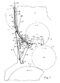
- a rotary printing press has several printing units 1 (e.g. 4), each of which, among other things. a plate cylinder 3, a blanket cylinder 4 and an impression cylinder 6 included. These are stored in the usual way in side frames of the rotary printing press.
- a printing plate feed or removal device 9 is provided on an access side 8 to the cylinders 3, 4, 6 of the printing unit 1. This is attached to a cover plate 11, which together with the pressure plate feed or discharge device 9 by means of two rockers (arms) 17; 18, which are fastened to the side frames of the printing towers 1, are arranged pivotably in two end positions.
- the swivel radius is shown by dashed lines.
- an upper and lower joint 14; 16 provided, in each of which a first end of the rockers 17; 18 is pivotally mounted.
- a second end of the rockers 17, 18 is pivotally mounted on the side frames.
- the cover plate 11 as a coupling, the wings 17, 18 and the frame of the printing unit 1 as a web thus form a four-bar link.
- a working cylinder 19 is pivotally mounted on a lower end on both sides of the cover plate 11.
- a piston rod 21 of the working cylinder 19 is articulated to a lever 22.
- the lever 22 rotatably supports a continuous pressure roller 26 arranged parallel to the axis of the plate cylinder 3.
- the pressure roller 26 can also be offset.
- the pressure roller 26 has a soft surface (e.g. rubber; plastic) in relation to a pressure plate 27.
- the lever 22 is pivotally mounted about an axis 30 of a drive roller 29 rotatably mounted in side supports (not shown) of the cover plate 11.
- the drive roller 29 is offset and has a drive (z. B. gear drive, electric motor, etc.).
- this is represented schematically by a chain wheel 31 with a drive chain 32.
- the drive roller 29 and the pressure roller 26 are also in drive connection, wherein they preferably have the same peripheral speeds.
- a pressure roller 33 can be brought into contact with a drive roller 29.
- the pressure roller 33 is rotatably mounted in a first end of a two-armed lever 34.
- the lever 34 is pivotably mounted almost centrally in the side supports of the cover plate 11 and has a joint 36 at a second end, which is connected to one end of a piston rod 37.
- the piston rod 37 is part of a working cylinder 40 which is articulated to the cover plate 11.
- the printing plate feed or discharge device 9 consists of an approximately printing plate-wide housing 38 with a storage chamber 39.
- the housing 38 has a slight curvature such that an upper part of the housing 38 is aligned almost vertically and a lower part of the Housing 38 is oriented tangentially to a lower part of the plate cylinder 3.
- a funnel-shaped opening 41 in the upper part of the housing 38 facilitates the insertion of the pressure plate 27.
- the housing 38 is made in two parts and has a hinge 42 above the cover plate 11, by means of which an upper part of the housing 38 can be folded down, whereby an upper part of the printing tower 1, in which an inking unit (not shown) in the usual manner Printing machine is provided, is accessible to an operator.
- a front wall 43 of the housing 38 extends up to shortly before the pressure roller 26 and has openings 44 in the area of the drive roller 29, through which surface areas of the remote drive roller 29 protrude into the storage chamber 39.
- a rear wall 46 of the housing 38 extends shortly before the pressure roller 33.
- a plurality of ejection fingers 45 are provided parallel to the front wall 43, which are fixedly arranged on an ejection finger shaft 47 pivotably mounted in the side supports of the cover plate 11.
- a drive device for the ejection finger shaft 47 is shown in FIG. 2. At a distance from the pivotable mounting of the ejection finger shaft 47, a piston rod 48 articulates on a lever 50 of the ejection finger shaft 47.
- the piston rod 48 is part of a working cylinder 49, the is articulated to the cover plate 11.
- the ejection fingers 45 are pivoted by means of the piston rod 48 in such a way that their tips 68 can dip into the periphery 62 of the plate cylinder 3 or lift off over the periphery.
- Means are also provided (not shown) which cause the ejection fingers 45 to be able to dip into the periphery 62 of the plate cylinder only in the area of the plate cylinder pit 2.
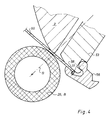
- the plate cylinder 3 has a plate clamping and tensioning device 53, 54 in a pit 52.
- the plate clamp is e.g. known from DE-PS 36 26 936. This is particularly characterized by a conveniently arranged pivot pole of the clamping flap 55; 56 out. This has the effect that a pressure plate end 57 is not hindered by the clamping flap 55 when it is inserted into or removed from the plate clamping device 54.
- the jig is e.g. known from DE-OS 36 04 071.
- actuating means for the plate clamping and tensioning device 53, 54 are supplied with working medium via a rotary entry on the plate cylinder journal.
- the actuating means can act hydraulically, pneumatically, mechanically or also electrically.
- the printing plate feed or discharge device 9 is in a position according to FIGS. 1 and 2. In this position, access to the cylinders 3, 4, 6 is closed by the cover plate 11, but the pressure roller 26 is pivoted from the plate cylinder 3 (not shown).
- the cover plate 11 has a view (not shown) on the plate cylinder 3.
- the plate cylinder 3 moves into the predetermined angular position A (FIG. 2).
- the clamping flap 55 is opened.
- a pressure plate end 57 pivots outward due to its elastic inherent tension until it rests against a lower part of the front wall 43 or is lifted from the clamping support 63 by the ejection fingers 45 by rotating the plate cylinder 3 into the pressure plate clamping position C by the ejection fingers 45.
- the pressure plate end 57 thereby comes into a nip of the transport rollers (drive roller / Pressure roller) 29, 33, which grip the printing plate end 57 and transport the printing plate 27 further at the same or greater peripheral speed as the plate cylinder 3, when the clamping flap 56 of the plate clamping and tensioning device 53 for the printing plate start 58 in the plate cylinder angle position B (printing plate feed position) (FIG 1) or was opened shortly before.
- the pressure plate 27 is transported by the transport rollers 29, 33 until the pressure plate end 57 of the pressure plate 27 has left the nip, i.e. is transported out of the lower part of the printing plate feed or discharge device 9. An operator can now grasp the pressure plate end 57 and remove the pressure plate 27 from the storage chamber 39.
- the plate cylinder 3 is now rotated counterclockwise (forward) while the pressure roller 26 presses the pressure plate 60 against the plate cylinder 3. If the position detector 59 signals that the printing plate 60 is not in good contact with the stop 51 of the plate clamping device 54, the printing plate clamping process is terminated and an interference signal is generated.
- the position C is subdivided into angular degrees only slightly (approx. 5 ° - 10 °) behind the disposal position A, i.e. H. the plate cylinder 3 only has to be rotated a little bit counterclockwise from the disposal position A until it reaches position C (FIG. 3).
- the pressure roller 26 has slightly bent the pressure plate end 57 around an edge 61 of the plate cylinder pit 52, so that the pressure plate end 57 comes to lie within the periphery 62 of the plate cylinder 3 on the clamping support 63 of the clamping device 54 before it comes off the clamping flap 55 is held.
- the pressure roller 26 is then pivoted back into the printing press operating position in that the double-acting working cylinder 19 pressurizes the piston rod 21, and the pressure roller 26 swivels about the axis 30 of the drive roller 29 from the plate cylinder 3.
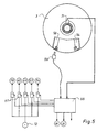
- the control computer 66 is connected to a number of solenoid valves 67 which, in the event of a command, switch or supply printing plate in the correct sequence depending on the positions of the plate cylinder 3 and in conjunction with suitable software and supply the actuating cylinders with working medium from a pressure source 72.
- the positions A, B, C of the plate cylinder 3 are determined by means of an angle encoder 71 and fed to the control computer 66 (FIG. 4).
- All electrical drives e.g. plate cylinder drive M, drive for the transport roller 33
- All electrical drives are also controlled by means of the control computer 66.
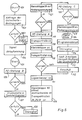
- FIG. 6 shows the diagram of a flow chart according to which the control computer 66 works in conjunction with counters and other position indicators (e.g. rotary pulse encoder 71) so that the printing plate 60 is automatically fed to the plate cylinder 3.
- the control computer 66 works in conjunction with counters and other position indicators (e.g. rotary pulse encoder 71) so that the printing plate 60 is automatically fed to the plate cylinder 3.
- a query 102 of the safety conditions (for example, is the cover plate 11 closed?) Is carried out. Appropriate sensors are then activated. Not all If safety conditions are met, an interference signal 103 is generated.
- a start warning signal 104 is given when all safety conditions are met.
- a renewed actuation of the start trigger 101 activates a drive of the plate cylinder 3 and rotates it into the plate cylinder position B (printing plate feed position) 106.
- the drive stops.
- a subsequent query 107 relates to the presence of a new printing plate 60 in the printing plate feed or discharge device 9. Sensors provided but not shown to signal that the new printing plate 60 is missing, an interference signal 108 is generated.
- a step 109 the clamping flap 56 is opened, the pressure roller 26 is placed against the plate cylinder 3, and the drive for all transport rollers 26, 29, 33 is activated.
- the position detector 59 is then queried in a step 111. If the position of the pressure plate 60 on the stops 51 is incorrect, a further feed 112 of the pressure plate takes place. After three negative decisions 113, the transport rollers 26, 29, 33 are driven in reverse so that the printing plate 60 is transported back into the storage chamber 39; an interference signal 114 is also generated.
- step 116 If the pressure plate 60 is correctly positioned, the drive for the transport rollers 26, 29, 33 is switched off in a step 116.
- the clamping flap 56 is then closed in step 117 and the pressure roller 33 of in step 118 the drive roller 29 turned off.
- An activation 119 of the plate cylinder drive rotates the plate cylinder 3 forward into the plate cylinder position A.
- the clamping flap 55 is opened in a step 121 and the plate clamping device 54 is moved to zero.
- step 122 the plate cylinder 3 is moved into the plate cylinder position C.
- the plate cylinder 3 is not stopped between positions A and C.
- FIG. 7 shows the flowchart for releasing and removing the printing plate 27 from the plate cylinder 3 or pushing it into the printing plate memory 9.
- a query 202 of the safety conditions (e.g. is the cover plate 11 closed?) Is carried out. Appropriate sensors are then activated. Among other things, there is also a query as to whether the printing plate memory 9 is free. If these conditions are not met, an interference signal 203 is generated. If all safety conditions are met, a start-up warning signal 104 is generated.
- the plate cylinder 3 is rotated into the plate cylinder position A in step 205.
- the pressure roller 26 is placed against the plate cylinder 3 in a step 206.
- the pressure roller 33 is turned off by the drive roller 29.
- the ejection fingers 45 are activated and plunge into the periphery 62 of the plate cylinder 3.
- the plate tension is turned off, the clamping flap 55 is opened.
- a drive 31, 32 for the transport rollers 26, 29 is activated.
- the drive for the plate cylinder 3 is activated in step 208, so that it rotates backwards.
- step 209 after a plate cylinder rotation of approximately 50 mm in radians from plate cylinder position A, ejection fingers 45 are pivoted out of periphery 62 of plate cylinder 3.
- a subsequent step 211 after a plate cylinder rotation of approximately 150 mm in radians from plate cylinder position A, the pressure roller 33 is placed against the drive roller 29.
- step 212 the plate cylinder 3 moves into the plate cylinder position B.
- the clamping flap 56 is opened in the subsequent step 213.
- step 214 the pressure roller 29 is turned off.
- the drive 31, 32 for the transport rollers 29, 33 is issued after a transport path of approximately 150 mm in radians, starting from the plate cylinder position B.
Abstract
Description
Die Erfindung betrifft ein Verfahren und eine Einrichtung zur Durchführung des Verfahrens zum automatischen Zuführen einer Druckplatte zu einem bzw. Abführen von einem Plattenzylinder einer Rotationsdruckmaschine.The invention relates to a method and a device for carrying out the method for automatically feeding a printing plate to and discharging a plate cylinder of a rotary printing press.
Durch die EP-Anm. 02 68 857 ist eine halbautomatische Einrichtung bekannt, mit der es möglich ist, eine Druckplatte auf dem Plattenzylinder einer Rotationsdruckmaschine zu befestigen.Through the EP note. 02 68 857 a semi-automatic device is known with which it is possible to attach a printing plate on the plate cylinder of a rotary printing press.
Nachteilig an der Einrichtung nach der EP-Anm. 02 68 857 ist, daß die Druckplatte per Hand in die Klemmeinrichtung eingeführt werden muß; außerdem müssen die Befehle zum Auflegen der Druckplatte, Einklemmen und Spannen per Hand an einem Schaltpult eingegeben werden.A disadvantage of the device according to EP application. 02 68 857 is that the pressure plate must be inserted into the clamping device by hand; In addition, the commands for placing the pressure plate, clamping and clamping must be entered manually on a control panel.
Der Erfindung liegt die Aufgabe zugrunde, jeweils ein Verfahren zum Zu- und Abführen einer Druckplatte zu bzw. von einem Plattenzylinder und eine Einrichtung zur Durchführung der Verfahren zu schaffen.The invention has for its object to provide a method for feeding and discharging a printing plate to and from a plate cylinder and a device for performing the method.
Die Aufgabe wird erfindungsgemäß durch die Merkmale der kennzeichnenden Teile der Ansprüche 1, 2 und 4 gelöst.The object is achieved by the features of the characterizing parts of
Der Vorteil der erfindungsgemäßen Verfahren bzw. der Einrichtung liegt insbesondere darin, daß für das Befestigen der Druckplatten auf dem Plattenzylinder Hilfspersonal eingesetzt werden kann. Eine Berührung des Personals mit den rotierenden Teilen der Maschine wird ausgeschlossen, d.h. die Sicherheit wird erhöht. Stillstandszeiten der Maschine zum Wechseln der Druckplatten werden verkürzt.The advantage of the method and the device according to the invention is, in particular, that for attaching the printing plates to the plate cylinder Auxiliary staff can be used. Touching the personnel with the rotating parts of the machine is excluded, ie safety is increased. Machine downtimes for changing the printing plates are reduced.
Eine passerrelevante Lage der Platte auf dem Plattenzylinder wird präziser. Ein Makulaturanfall, der durch langwierige Passerkorrektur entsteht, wird vermindert.A position relevant to the plate on the plate cylinder becomes more precise. A waste of paper waste caused by lengthy registration correction is reduced.
Ein Ausführungsbeispiel der Erfindung ist in den Zeichnungen dargestellt und wird im folgenden beschrieben. Es zeigen
- Fig. 1
- eine Seitenansicht der erfindungsgemäßen Druckplattenzuführ- bzw. -abführvorrichtung im Schnitt, Druckplattenzuführstellung,
- Fig. 2
- wie Fig. 1, jedoch andere Winkelstellung des Plattenzylinders, Druckplattenlösestellung,
- Fig. 3
- eine vergrößerte Seitenansicht der Klemmeinrichtung für ein Druckplattenende, Druckplattenklemmstellung,
- Fig. 4
- eine vergrößerte Seitenansicht der Klemmeinrichtung für einen Druckplattenanfang,
- Fig. 5
- Steuereinrichtung und Steuerrechner,
- Fig. 6
- einen Ablaufplan für das Zuführen einer Druckplatte zum Plattenzylinder,
- Fig. 7
- einen Ablaufplan für das Abführen einer Druckplatte vom Plattenzylinder.
- Fig. 1
- a side view of the printing plate feed or discharge device according to the invention in section, printing plate feed position,
- Fig. 2
- like Fig. 1, but different angular position of the plate cylinder, printing plate release position,
- Fig. 3
- an enlarged side view of the clamping device for a printing plate end, printing plate clamping position,
- Fig. 4
- an enlarged side view of the clamping device for a printing plate start,
- Fig. 5
- Control device and control computer,
- Fig. 6
- a flow chart for feeding a printing plate to the plate cylinder,
- Fig. 7
- a flow chart for the removal of a printing plate from the plate cylinder.
Eine Rotationsdruckmaschine weist mehrere Druckwerke 1 (z.B. 4) auf, die jeweils u.a. einen Plattenzylinder 3, einen Gummituchzylinder 4 und einen Gegendruckzylinder 6 enthalten. Diese sind in üblicher Weise in Seitengestellen der Rotationsdruckmaschine gelagert.A rotary printing press has several printing units 1 (e.g. 4), each of which, among other things. a
Da die verschiedenen Druckwerke 1 untereinander nahezu gleich sind, wird die Erfindung nur anhand eines Druckwerkes 1 beschrieben.Since the
An einer Zugangsseite 8 zu den Zylindern 3, 4, 6 des Druckwerkes 1 ist eine Druckplattenzuführ- bzw. -abführvorrichtung 9 vorgesehen. Diese ist an einer Abdeckplatte 11 befestigt, welche zusammen mit der Druckplattenzuführ- bzw. -abführeinrichtung 9 mittels jeweils zweier Schwingen (Arme) 17; 18, die an den Seitengestellen der Drucktürme 1 befestigt sind, vertikal in zwei Endstellungen verschwenkbar angeordnet ist. Der Schwenkradius ist durch gestrichelte Linien dargestellt. Hierzu sind an einer vorderen und hinteren Seite der Abdeckplatte 11 jeweils ein oberes und unteres Gelenk 14; 16 vorgesehen, in der jeweils ein erstes Ende der Schwingen 17; 18 schwenkbar gelagert ist. Ein zweites Ende der Schwingen 17, 18 ist jeweils schwenkbar an den Seitengestellen gelagert. Die Abdeckplatte 11 als Koppel, die Schwingen 17, 18 und das Gestell des Druckwerkes 1 als Steg bilden somit ein Gelenkviereck.A printing plate feed or removal device 9 is provided on an
An einem unteren Ende an beiden Seiten der Abdeckplatte 11 ist jeweils ein Arbeitszylinder 19 schwenkbar gelagert. Eine Kolbenstange 21 des Arbeitszylinders 19 ist gelenkig mit einem Hebel 22 verbunden. Der Hebel 22 trägt in seinem Ende drehbar gelagert eine parallel zur Achse des Plattenzylinders 3 angeordnete, durchgehende Andrückwalze 26. Die Andrückwalze 26 kann auch abgesetzt sein. Die Andrückwalze 26 weist eine im Verhältnis zu einer Druckplatte 27 weiche Oberfläche (z.B. Gummi; Kunststoff) auf. Der Hebel 22 ist um eine Achse 30 einer drehbar in Seitenstützen (nicht dargestellt) der Abdeckplatte 11 gelagerten Antriebsrolle 29 schwenkbar gelagert. Die Antriebsrolle 29 ist abgesetzt und weist einen Antrieb (z. B. Zahnradantrieb, Elektromotor usw.) auf.A working
Im Ausführungsbeispiel ist dieser schematisch durch ein Kettenrad 31 mit Antriebskette 32 dargestellt.In the exemplary embodiment, this is represented schematically by a
Die Antriebsrolle 29 und die Andrückwalze 26 stehen ebenfalls in Antriebsverbindung, wobei sie vorzugsweise gleiche Umfangsgeschwindigkeiten aufweisen.The
Eine Andrückrolle 33 ist mit einer Antriebsrolle 29 in Berührung bringbar. Hierzu ist die Andrückrolle 33 in einem ersten Ende eines zweiarmigen Hebels 34 drehbar gelagert.A
Der Hebel 34 ist nahezu mittig in den Seitenstützen der Abdeckplatte 11 schwenkbar gelagert und weist an einem zweiten Ende ein Gelenk 36 auf, das mit einem Ende einer Kolbenstange 37 verbunden ist. Die Kolbenstange 37 ist Teil eines Arbeitszylinders 40, der gelenkig an der Abdeckplatte 11 befestigt ist.The
Die Druckplattenzuführ- bzw. -abführvorrichtung 9 besteht aus einem ca. druckplattenbreiten Gehäuse 38 mit einer Speicherkammer 39. Das Gehäuse 38 weist im Schnitt betrachtet eine leichte Krümmung derart auf, daß ein oberer Teil des Gehäuses 38 nahezu vertikal ausgerichtet ist und ein unterer Teil des Gehäuses 38 tangential auf einen unteren Teil des Plattenzylinders 3 hin ausgerichtet ist. Eine trichterförmige Öffnung 41 im oberen Teil des Gehäuses 38 erleichtert das Einschieben der Druckplatte 27.The printing plate feed or discharge device 9 consists of an approximately printing plate-
Das Gehäuse 38 ist zweiteilig ausgeführt und weist oberhalb der Abdeckplatte 11 ein Scharnier 42 auf, mittels dessen ein oberer Teil des Gehäuses 38 nach unten abklappbar ist, wodurch ein oberer Teil des Druckturmes 1, in dem in üblicher Weise ein Farbwerk (nicht dargestellt) der Druckmaschine vorgesehen ist, einer Bedienperson zugänglich ist.The
Eine Vorderwand 43 des Gehäuses 38 erstreckt sich bis kurz vor die Andrückwalze 26 und weist im Bereich der Antriebsrolle 29 Durchbrüche 44 auf, durch welche Oberflächenbereiche der abgesetzten Antriebsrolle 29 in die Speicherkammer 39 hineinragen. Eine Rückwand 46 des Gehäuses 38 erstreckt sich bis kurz vor die Andrückrolle 33. Hinter der Andrückrolle 33 sind parallel zur Vorderwand 43 mehrere Auswurffinger 45 vorgesehen, die fest auf einer schwenkbar in den Seitenstützen der Abdeckplatte 11 gelagerten Auswurffingerwelle 47 angeordnet sind. Eine Antriebsvorrichtung für die Auswurffingerwelle 47 zeigt Fig. 2. In einem Abstand von der schwenkbaren Lagerung der Auswurffingerwelle 47 greift eine Kolbenstange 48 gelenkig an einem Hebel 50 der Auswurffingerwelle 47 an. Die Kolbenstange 48 ist Teil eines Arbeitszylinders 49, der gelenkig an der Abdeckplatte 11 befestigt ist. Die Auswurffinger 45 sind mittels der Kolbenstange 48 derart schwenkbar gelagert, daß ihre Spitzen 68 in die Peripherie 62 des Plattenzylinders 3 eintauchen bzw. über die Peripherie abheben können.A front wall 43 of the
Ferner sind Mittel vorgesehen (nicht dargestellt), die bewirken, daß die Auswurffinger 45 nur im Bereich der Plattenzylindergrube 2 in die Peripherie 62 des Plattenzylinders eintauchen können.Means are also provided (not shown) which cause the
Der Plattenzylinder 3 weist in einer Grube 52 eine Plattenklemm- und Spannvorrichtung 53, 54 auf. Die Plattenklemmvorrichtung ist z.B. durch die DE-PS 36 26 936 bekannt. Diese zeichnet sich insbesondere durch einen günstig angeordneten Schwenkpol der Klemmklappe 55; 56 aus. Dieser bewirkt, daß ein Druckplattenende 57 beim Einlegen in die bzw. Herausnehmen aus der Plattenklemmvorrichtung 54 nicht durch die Klemmklappe 55 behindert wird.The
Die Spannvorrichtung ist z.B. durch die DE-OS 36 04 071 bekannt.The jig is e.g. known from DE-OS 36 04 071.
Bei Drehung des Plattenzylinders 3 aus einer Druckplattenlösestellung A im Uhrzeigersinn (rückwärts) und Druckbeaufschlagung des Arbeitszylinders 49 gelangen die Spitzen 68 der Greiferfinger 45 durch entsprechende Durchbrüche 64 in der Klemmklappe 55 hindurch in Ausnehmungen 65 in der Plattenklemm- und Spannvorrichtung 54 unter das Druckplattenende 57 und unterstützen somit ein Abheben des Druckplattenendes 57 von einer Klemmauflage 63.Upon rotation of the
Vorgesehene Stellmittel für die Plattenklemm- und Spannvorrichtung 53,54 werden über eine Dreheinführung am Plattenzylinderzapfen mit Arbeitsmedium versorgt. Selbstverständlich ist es auch möglich, Einrichtungen vorzusehen, die bei einem Stillstand des Plattenzylinders 3 in einer Plattenzylinderstellung A, B, C diesen über seine Stirnseite oder Mantelfläche mit Arbeitsmedium versorgen. Die Stellmittel können hydraulisch, pneumatisch, mechanisch oder oder auch elektrisch wirken.Provided actuating means for the plate clamping and
Im Druckbetrieb befindet sich die Druckplattenzuführ- bzw. -abführvorrichtung 9 in einer Stellung gemäß der Fig. 1 und Fig. 2. In dieser Stellung ist der Zugang zu den Zylindern 3, 4, 6 durch die Abdeckplatte 11 verschlossen, die Andrückwalze 26 ist jedoch vom Plattenzylinder 3 abgeschwenkt (nicht gezeigt). Die Abdeckplatte 11 weist eine Durchblickmöglichkeit (nicht dargestellt) auf den Plattenzylinder 3 auf.In printing operation, the printing plate feed or discharge device 9 is in a position according to FIGS. 1 and 2. In this position, access to the
In einer Druckplattenlöse- bzw. -zuführstellung A, B ist die Andrückrolle 26 an den Plattenzylinder 3 angestellt.In a printing plate release or feed position A, B, the
Nach Beendigung des laufenden Druckauftrages fährt der Plattenzylinder 3 in die vorbestimmte Winkelstellung A (Fig. 2). Die Klemmklappe 55 wird geöffnet. Ein Druckplattenende 57 schwenkt durch seine elastische Eigenspannung nach außen, bis es an einem unteren Teil der Vorderwand 43 anliegt oder wird durch Weiterdrehen des Plattenzylinders 3 in die Druckplattenklemmstellung C durch die Auswurffinger 45 von der Klemmauflage 63 abgehoben.After the end of the current print job, the
Eine Drehung des Plattenzylinders 3 in Verbindung mit der angetriebenen Andrückwalze 26 im Uhrzeigersinn (rückwärts) bewirkt nun das Abführen der Druckplatte 27 vom Plattenzylinder 3 bzw. Einschieben der Druckplatte 27 in die Speicherkammer 39. Hierbei gelangt das Druckplattenende 57 in einen Walzenspalt der Transportrollen (Antriebsrolle/ Andrückrolle) 29, 33, die das Druckplattenende 57 erfassen und mit gleicher oder größerer Umfangsgeschwindigkeit wie der Plattenzylinder 3 die Druckplatte 27 weitertransportieren, wenn die Klemmklappe 56 der Plattenklemm- und Spannvorrichtung 53 für den Druckplattenanfang 58 in der Plattenzylinderwinkelstellung B (Druckplattenzuführstellung) (Fig. 1) bzw. kurz zuvor geöffnet wurde. Die Druckplatte 27 wird durch die Transportrollen 29, 33 soweit transportiert, bis das Druckplattenende 57 der Druckplatte 27 den Walzenspalt verlassen hat, d.h. aus dem unteren Teil der Druckplattenzuführ- bzw. -abführvorrichtung 9, heraustransportiert ist. Eine Bedienperson kann nun das Druckplattenende 57 erfassen und die Druckplatte 27 aus der Speicherkammer 39 herausnehmen.A rotation of the
Zur Bestückung des Plattenzylinders 3 mit einer neuen Druckplatte 60 stellt eine Bedienperson die neue Druckplatte 60 mit dem Druckplattenanfang 58 voran in die Speicherkammer 39, bis diese an den Transportrollen 29, 33 anliegt. Der Plattenzylinder 3 steht in der Druckplattenzuführstellung B (Fig. 1), und die Klemmklappe 56 ist geöffnet. Nun werden die Transportrollen 29, 33 aktiviert und transportieren die neue Druckplatte 60 aus der Speicherkammer 39, bis der Druckplattenanfang 58 gegen einen Anschlag 51 der Plattenklemm- und Spannvorrichtung 53 stößt. Ein Lageerkenner 59 für die Anlage der Druckplatte (27; 60) an dem Anschlag 51 gibt ein "Gut"-Signal an einen Steuerrechner 66, woraufhin die Klemmklappe 56 geschlossen wird. Der Druckplattenanfang 58 ist festgeklemmt. Der Plattenzylinder 3 wird nun entgegen dem Uhrzeigersinn (vorwärts) gedreht, während die Andrückwalze 26 die Druckplatte 60 gegen den Plattenzylinder 3 andrückt. Signalisiert der Lageerkenner 59 eine schlechte Anlage der Druckplatte 60 an dem Anschlag 51 der Plattenklemmeinrichtung 54, wird der Druckplattenklemmvorgang abgebrochen und ein Störsignal erzeugt.To equip the
Bei Erreichen einer Plattenzylinderstellung (Druckplattenklemmstellung) C (Fig. 3), bei der das Druckplattenende 57 durch die Andrückwalze 26 auf die Klemmfläche 63 gedrückt wird, schließt die Klemmklappe 55 und klemmt das Druckplattenende 57 fest. Eine anschließende Aktivierung der Spannelemente spannt die Druckplatte 60 auf dem Plattenzylinder 3.When a plate cylinder position (printing plate clamping position) C (FIG. 3) is reached, in which the
Die Stellung C liegt in Winkelgrade unterteilt nur wenig (ca. 5° - 10°) hinter der Entsorgungsstellung A, d. h. der Plattenzylinder 3 muß aus der Entsorgungsstellung A nur ein kleines Stück gegen den Uhrzeigersinn verdreht werden, bis er die Stellung C (Fig. 3) erreicht.The position C is subdivided into angular degrees only slightly (approx. 5 ° - 10 °) behind the disposal position A, i.e. H. the
In der Stellung C hat die Andrückwalze 26 das Druckplattenende 57 leicht um eine Kante 61 der Plattenzylindergrube 52 gebogen, so daß das Druckplattenende 57 innerhalb der Peripherie 62 des Plattenzylinders 3 auf der Klemmauflage 63 der Klemmvorrichtung 54 zu liegen kommt, bevor es von der Klemmklappe 55 festgehalten wird.In position C, the
Die Andrückwalze 26 wird daraufhin in die Druckmaschinenbetriebsstellung zurückgeschwenkt, indem der doppeltwirkende Arbeitszylinder 19 mit Druckmittel beaufschlagt die Kolbenstange 21 einfährt und die Andrückwalze 26 um die Achse 30 der Antriebsrolle 29 vom Plattenzylinder 3 abschwenkt.The
Der Steuerrechner 66 ist mit einer Anzahl Elektromagnetventilen 67 verbunden, die bei einem Kommando Druckplattenzufuhr bzw. -abfuhr in Abhängigkeit von den Stellungen des Plattenzylinders 3 und in Verbindung mit einer geeigneten Software in richtiger Reihenfolge schalten und die Stellzylinder mit Arbeitsmedium aus einer Druckquelle 72 versorgen.The
Die Stellungen A, B, C des Plattenzylinders 3 werden mittels eines Drehwinkelgebers 71 ermittelt und dem Steuerrechner 66 zugeführt (Fig. 4).The positions A, B, C of the
Es werden ebenfalls sämtliche elektrischen Antriebe (z.B. Plattenzylinderantrieb M, Antrieb für die Transportrolle 33) mittels des Steuerrechners 66 gesteuert.All electrical drives (e.g. plate cylinder drive M, drive for the transport roller 33) are also controlled by means of the
Die Fig. 6 zeigt das Schema eines Ablaufplanes, nach welchem der Steuerrechner 66 in Verbindung mit Zählern und anderen Stellungsanzeigen (z.B. Drehimpulsgeber 71) arbeitet, damit die Druckplatte 60 automatisch dem Plattenzylinder 3 zugeführt wird.6 shows the diagram of a flow chart according to which the
Durch Betätigung eines Startauslösers 101 wird eine Abfrage 102 der Sicherheitsbedingungen (z.B. Ist die Abdeckplatte 11 geschlossen ?) durchgeführt. Entsprechende Sensoren werden daraufhin aktiviert. Sind nicht sämtliche Sicherheitsbedingungen erfüllt, wird ein Störsignal 103 erzeugt.By actuating a
Bei Erfüllung sämtlicher Sicherheitsbedingungen wird ein Anlaufwarnsignal 104 gegeben. Eine erneute Betätigung des Startauslösers 101 aktiviert einen Antrieb des Plattenzylinders 3 und verdreht ihn in die Plattenzylinderstellung B (Druckplattenzuführstellung) 106. Bei Erreichen der Plattenzylinderstellung B stoppt der Antrieb.A
Eine anschließende Abfrage 107 betrifft das Vorhandensein einer neuen Druckplatte 60 in der Druckplattenzuführ- bzw. -abführvorrichtung 9. Signalisieren vorgesehene, jedoch nicht dargestellte Sensoren, daß die neue Druckplatte 60 fehlt, wird ein Störsignal 108 erzeugt. In einem Schritt 109 wird die Klemmklappe 56 geöffnet, die Andrückwalze 26 wird an den Plattenzylinder 3 angestellt, und der Antrieb für sämtliche Transportrollen 26, 29, 33 wird aktiviert.A
Danach wird in einem Schritt 111 der Lageerkenner 59 abgefragt. Ist die Lage der Druckplatte 60 an den Anschlägen 51 nicht korrekt, erfolgt ein weiterer Vorschub 112 der Druckplatte. Nach dreimaligem negativen Bescheid 113 werden die Transportrollen 26, 29, 33 rückwärts angetrieben, so daß die Druckplatte 60 in die Speicherkammer 39 zurücktransportiert wird; außerdem wird ein Störsignal 114 erzeugt.The
Bei korrekter Anlage der Druckplatte 60 wird in einem Schritt 116 der Antrieb für die Transportrollen 26, 29, 33 abgestellt. Daraufhin wird im Schritt 117 die Klemmklappe 56 geschlossen und im Schritt 118 die Andrückrolle 33 von der Antriebsrolle 29 abgestellt.If the
Eine Aktivierung 119 des Plattenzylinderantriebs dreht den Plattenzylinder 3 vorwärts in die Plattenzylinderstellung A. Ist die Stellung erreicht, werden in einem Schritt 121 die Klemmklappe 55 geöffnet und die Plattenspanneinrichtung 54 auf Null gefahren.An
In Schritt 122 wird der Plattenzylinder 3 in die Plattenzylinderstellung C gefahren. Der Plattenzylinder 3 wird zwischen den Stellungen A und C nicht angehalten.In
Bei Erreichen der Plattenzylinderstellung C wird in einem Schritt 123 die Klemmklappe 55 geschlossen und daraufhin die Plattenspanneinrichtung 54 aktiviert. Danach wird ein Signal Ende 124 erzeugt.When the plate cylinder position C is reached, the clamping
Die Fig. 7 zeigt den Ablaufplan für das Lösen und Abführen der Druckplatte 27 vom Plattenzylinder 3 bzw. Einschieben in den Druckplattenspeicher 9.FIG. 7 shows the flowchart for releasing and removing the
Durch Betätigung eines Startauslösers 201 wird eine Abfrage 202 der Sicherheitsbedingungen (z.B. Ist die Abdeckplatte 11 geschlossen ?) durchgeführt. Entsprechende Sensoren werden daraufhin aktiviert. Unter anderem erfolgt auch die Abfrage, ob der Druckplattenspeicher 9 frei ist. Sind diese Bedingungen nicht erfüllt, wird ein Störsignal 203 erzeugt. Sind sämtliche Sicherheitsbedingungen erfüllt, wird ein Anlaufwarnsignal 104 erzeugt.By actuating a
Durch eine erneute Betätigung des Startauslösers 201 wird der Plattenzylinder 3 im Schritt 205 in die Plattenzylinderstellung A verdreht. Bei Erreichen der Plattenzylinderstellung A wird in einem Schritt 206 die Andrückrolle 26 an den Plattenzylinder 3 angestellt. Die Andrückrolle 33 wird von der Antriebsrolle 29 abgestellt. Die Auswurffinger 45 werden aktiviert und tauchen in die Peripherie 62 des Plattenzylinders 3 ein. Die Plattenspannung wird abgestellt, die Klemmklappe 55 wird geöffnet.By actuating the
Danach wird in einem Schritt 207 ein Antrieb 31, 32 für die Transportrollen 26, 29 aktiviert. Gleichzeitig wird im Schritt 208 der Antrieb für den Plattenzylinder 3 aktiviert, so daß dieser rückwärts dreht.Then, in a
Im Schritt 209 werden nach einer Plattenzylinderdrehung von ca. 50 mm im Bogenmaß aus der Plattenzylinderstellung A die Auswurffinger 45 aus der Peripherie 62 des Plattenzylinders 3 herausgeschwenkt.In
In einem nachfolgenden Schritt 211 wird nach einer Plattenzylinderdrehung von ca. 150 mm im Bogenmaß aus der Plattenzylinderstellung A die Andrückrolle 33 an die Antriebsrolle 29 angestellt.In a
Im Schritt 212 fährt der Plattenzylinder 3 bis in die Plattenzylinderstellung B. Die Klemmklappe 56 wird im nachfolgenden Schritt 213 geöffnet.In
Im Schritt 214 wird die Andrückwalze 29 abgestellt.In
Im letzten Schritt 216 wird der Antrieb 31, 32 für die Transportrollen 29, 33 nach einem Transportweg von ca. 150 mm im Bogenmaß, ausgehend von der Plattenzylinderstellung B, ausgestellt.In the
- 11
- Druckwerk Printing unit
- 22nd
- - -
- 33rd
- Plattenzylinder Plate cylinder
- 44th
- Gummituchzylinder Blanket cylinder
- 55
- - -
- 66
- Gegendruckzylinder Impression cylinder
- 77
- - -
- 88th
- Zugangsseite Access page
- 99
- Druckplattenzuführ- bzw. -abführvorrichtung Printing plate feed or discharge device
- 1010th
- - -
- 1111
- Abdeckplatte Cover plate
- 1212
- - -
- 1313
- - -
- 1414
- Gelenk (oberes) Joint (upper)
- 1515
- - -
- 1616
- Gelenk (unteres) Joint (lower)
- 1717th
- Schwinge Swingarm
- 1818th
- Schwinge Swingarm
- 1919th
- Arbeitszylinder Working cylinder
- 2020th
- - -
- 2121
- Kolbenstange Piston rod
- 2222
- Hebel lever
- 2323
- - -
- 2424th
- - -
- 2525th
- - -
- 2626
- Andrückwalze Pressure roller
- 2727th
- Druckplatte printing plate
- 2828
- - -
- 2929
- Antriebsrolle Drive roller
- 3030th
- Achseaxis
- 3131
- Kettenrad Sprocket
- 3232
- Antriebskette Drive chain
- 3333
- Andrückrolle Pressure roller
- 3434
- Hebel lever
- 3535
- - -
- 3636
- Gelenk joint
- 3737
- Kolbenstange Piston rod
- 3838
- Gehäuse (9) Housing (9)
- 3939
- Speicherkammer Storage chamber
- 4040
- Arbeitszylinder Working cylinder
- 4141
- Öffnung opening
- 4242
- Scharnier hinge
- 4343
- Vorderwand (38) Front wall (38)
- 4444
- Durchbrüche Breakthroughs
- 4545
- Auswurffinger Ejection finger
- 4646
- Rückwand (38) Rear wall (38)
- 4747
- Auswurffingerwelle Ejection finger wave
- 4848
- Kolbenstange Piston rod
- 4949
- Arbeitszylinder Working cylinder
- 5050
- Hebel lever
- 5151
- Anschlag attack
- 5252
- Grube (3) Pit (3)
- 5353
- Plattenklemm- und Spannvorrichtung Plate clamping and tensioning device
- 5454
- Plattenklemm- und Spannvorrichtung Plate clamping and tensioning device
- 5555
- Klemmklappe Clamp flap
- 5656
- Klemmklappe Clamp flap
- 5757
- Druckplattenende Pressure plate end
- 5858
- Druckplattenanfang Printing plate start
- 5959
- Lageerkenner Location detectors
- 6060
- Druckplatte (neu)Pressure plate (new)
- 6161
- Kante (52) Edge (52)
- 6262
- Peripherie (3) Periphery (3)
- 6363
- Klemmauflage (54) Clamping pad (54)
- 6464
- Durchbrüche Breakthroughs
- 6565
- Ausnehmung (54) Recess (54)
- 6666
- Steuerrechner Tax calculator
- 6767
- Elektromagnetventil Solenoid valve
- 6868
- Spitze (45) Lace (45)
- 6969
- - -
- 7070
- - -
- 7171
- Drehwinkelgeber Angle of rotation encoder
- 7272
- Druckquelle Pressure source
- 101 )101)
- . ). )
- . ). )
- Folgeschritte des Ablaufplanes Follow-up steps to the schedule
- . ). )
- "Druckplattenzufuhr" "Printing plate feed"
- 124 )124)
- 201 )201)
- . ). )
- . ). )
- Folgeschritte des Ablaufplanes Follow-up steps to the schedule
- . ). )
- "Druckplattenabfuhr" "Printing plate removal"
- 216 )216)
- AA
- Druckplattenlösestellung Pressure plate release position
- BB
- Druckplattenzuführstellung Printing plate feed position
- CC.
- Druckplattenklemmstellung Pressure plate clamping position
Claims (14)
Applications Claiming Priority (2)
| Application Number | Priority Date | Filing Date | Title |
|---|---|---|---|
| DE3940795 | 1989-12-09 | ||
| DE3940795A DE3940795A1 (en) | 1989-12-09 | 1989-12-09 | METHOD AND DEVICE FOR AUTOMATIC FEEDING OR REMOVING A PRINT PLATE |
Publications (3)
| Publication Number | Publication Date |
|---|---|
| EP0433798A2 true EP0433798A2 (en) | 1991-06-26 |
| EP0433798A3 EP0433798A3 (en) | 1991-09-18 |
| EP0433798B1 EP0433798B1 (en) | 1995-10-18 |
Family
ID=6395177
Family Applications (1)
| Application Number | Title | Priority Date | Filing Date |
|---|---|---|---|
| EP90123550A Expired - Lifetime EP0433798B1 (en) | 1989-12-09 | 1990-12-07 | Device for exchanging a printing plate |
Country Status (11)
| Country | Link |
|---|---|
| US (1) | US5127328A (en) |
| EP (1) | EP0433798B1 (en) |
| JP (1) | JP2826191B2 (en) |
| CN (1) | CN1019082B (en) |
| AT (1) | ATE129191T1 (en) |
| AU (1) | AU644616B2 (en) |
| BR (1) | BR9006240A (en) |
| CS (1) | CS277515B6 (en) |
| DE (2) | DE3940795A1 (en) |
| ES (1) | ES2079421T3 (en) |
| RU (1) | RU2009045C1 (en) |
Cited By (17)
| Publication number | Priority date | Publication date | Assignee | Title |
|---|---|---|---|---|
| EP0530577A1 (en) * | 1991-08-31 | 1993-03-10 | Heidelberger Druckmaschinen Aktiengesellschaft | Device for positioning a loader used for automatically exchanging printing plates |
| EP0567754A1 (en) * | 1992-04-29 | 1993-11-03 | Heidelberger Druckmaschinen Aktiengesellschaft | Device for feeding a printing plate to the plate cylinder of a printing machine |
| DE4220011A1 (en) * | 1992-05-16 | 1993-11-18 | Kba Planeta Ag | Automatic fitting and/or removal of flexible forme plates - guides forme plate from feeder via intermediate feeders by auxiliary grippers on intermediate cylinder |
| EP0570702A1 (en) * | 1992-05-18 | 1993-11-24 | MAN Roland Druckmaschinen AG | Device for feeding printing plates to the plate cylinder of a printing machine, in particular offset sheet-fed printing machine |
| EP0579017A1 (en) * | 1992-06-30 | 1994-01-19 | LEHNER GmbH | Device for tensioning a printing plate on a plate cylinder |
| EP0581212A1 (en) * | 1992-07-31 | 1994-02-02 | Komori Corporation | Plate mounting apparatus for printing press |
| WO1994006632A1 (en) * | 1992-09-18 | 1994-03-31 | Koenig & Bauer Aktiengesellschaft | Device for supplying printing plates to a plate cylinder and for carrying away the same from the plate cylinder |
| WO1994006631A1 (en) * | 1992-09-18 | 1994-03-31 | Koenig & Bauer Aktiengesellschaft | Device for supplying printing plates to a plate cylinder and for carrying the same away from the plate cylinder |
| EP0712725A3 (en) * | 1994-11-10 | 1996-06-05 | Roland Man Druckmasch | |
| US5526747A (en) * | 1994-04-18 | 1996-06-18 | Heidelberger Druckmaschinen Ag | Device for replacing printing plates in rotary printing presses |
| EP0727311A1 (en) * | 1995-02-18 | 1996-08-21 | MAN Roland Druckmaschinen AG | Device for changing printing plates |
| EP0654349B2 (en) † | 1993-11-18 | 1999-12-29 | MAN Roland Druckmaschinen AG | Cassette for automatically exchanging printing plates in a printing machine |
| US6231167B1 (en) | 1996-07-09 | 2001-05-15 | Canon Kabushiki Kaisha | Liquid discharging head, liquid discharging method, head cartridge, liquid discharging apparatus, liquid discharging printing method, printing system, head kit and head recovery method |
| US6516723B1 (en) | 1999-03-31 | 2003-02-11 | Heidelberger Druckmaschinen Ag | Printing-plate changer assembly |
| DE102006006330B3 (en) * | 2006-02-11 | 2007-04-12 | Koenig & Bauer Ag | Printing mechanism with platen moving device for rotary printing press has fixed guide sector remote from platen cylinder |
| DE202008015082U1 (en) | 2008-11-13 | 2009-01-15 | Manroland Ag | Device for changing and receiving printing forms on rotary printing machines |
| DE102008043725A1 (en) | 2008-11-13 | 2010-06-02 | Manroland Ag | Device for exchanging and for receiving printing plates at rotary printing presses, comprises manipulator arm with holding element for holding printing plate |
Families Citing this family (72)
| Publication number | Priority date | Publication date | Assignee | Title |
|---|---|---|---|---|
| US5289773A (en) * | 1991-03-14 | 1994-03-01 | Komori Corporation | Apparatus for mounting plate on plate cylinder |
| JP3030573B2 (en) * | 1991-05-30 | 2000-04-10 | 株式会社小森コーポレーション | Plate mounting device on plate cylinder |
| DE4218602C2 (en) * | 1991-08-28 | 1993-11-11 | Heidelberger Druckmasch Ag | Device for inserting the pressure plate trailing edge on a plate cylinder |
| DE4130359C2 (en) * | 1991-09-12 | 1997-04-17 | Heidelberger Druckmasch Ag | Device for removing and / or feeding printing plates from a printing press |
| JP2765305B2 (en) * | 1991-10-25 | 1998-06-11 | トヨタ自動車株式会社 | Internal combustion engine |
| JP2917617B2 (en) * | 1991-10-28 | 1999-07-12 | トヨタ自動車株式会社 | Internal combustion engine |
| DE4140413C2 (en) * | 1991-12-07 | 1995-03-16 | Roland Man Druckmasch | Device for changing printing plates in offset printing machines |
| JP2585989Y2 (en) * | 1991-12-11 | 1998-11-25 | 株式会社小森コーポレーション | Plate mounting device on plate cylinder |
| US5272977A (en) * | 1992-02-05 | 1993-12-28 | Toshiba Kikai Kabushiki Kaisha | Printing plate mounting apparatus, printing plate replacement apparatus and printing plate replacement method |
| DE4214168C2 (en) * | 1992-04-30 | 1994-10-06 | Roland Man Druckmasch | Device for clamping printing plates on the plate cylinder of printing machines, in particular sheet-fed offset printing machines |
| DE4214207C1 (en) * | 1992-04-30 | 1993-07-22 | Man Roland Druckmaschinen Ag, 6050 Offenbach, De | |
| JP3219908B2 (en) * | 1992-07-09 | 2001-10-15 | ハイデルベルガー ドルツクマシーネン アクチエンゲゼルシヤフト | Sheet-fed offset printing press |
| DE4226780C2 (en) * | 1992-08-13 | 1994-12-01 | Roland Man Druckmasch | Device for checking the correct registration of a printing plate on the plate cylinder of printing machines, in particular sheetfed offset printing machines |
| DE4331430A1 (en) * | 1992-09-18 | 1994-03-24 | Koenig & Bauer Ag | Device for feeding and removing printing plates |
| DE4394496D2 (en) * | 1992-09-18 | 1995-09-21 | Koenig & Bauer Ag | Process for feeding printing plates |
| DE4309658C1 (en) * | 1993-03-25 | 1994-10-27 | Roland Man Druckmasch | Device for automatically changing printing plates in sheet-fed offset printing machines with several printing units |
| WO1994026519A2 (en) * | 1993-05-12 | 1994-11-24 | Deritend Engineering Limited | Board treatment apparatus |
| US5456175A (en) * | 1993-08-24 | 1995-10-10 | Sony Corporation | Printing sheet making and printing apparatus |
| JPH07148911A (en) * | 1993-11-26 | 1995-06-13 | Sakurai Graphic Syst:Kk | Auxiliary device for setting press plate for printer |
| DE4414443C1 (en) * | 1994-04-26 | 1995-11-30 | Heidelberger Druckmasch Ag | Device for guiding a print carrier |
| JP3592760B2 (en) * | 1994-10-12 | 2004-11-24 | 株式会社小森コーポレーション | Automatic plate changing method and apparatus for rotary printing press |
| FR2732268B1 (en) * | 1995-03-31 | 1997-06-20 | Heidelberg Harris Sa | DEVICE FOR EXCHANGING PRINTING PLATES |
| US6113346A (en) | 1996-07-31 | 2000-09-05 | Agfa Corporation | Method for loading and unloading a supply of plates in an automated plate handler |
| JPH1120131A (en) * | 1997-07-03 | 1999-01-26 | Ryobi Ltd | Press plate gripper for printer |
| US6112664A (en) * | 1998-04-13 | 2000-09-05 | Fuji Photo Film Co., Ltd. | Plate making apparatus with a cutter and punch mechanism formed in one piece |
| DE19934271A1 (en) | 1998-11-13 | 2000-05-25 | Heidelberger Druckmasch Ag | Device for exchanging type formes on rotary printing machines has separately operable contact body bearing against surface of tpe forme which is now able to move into any desired position |
| DE10008489B4 (en) * | 1999-03-19 | 2006-08-24 | Heidelberger Druckmaschinen Ag | Method and device for feeding a printing plate |
| DE19933943A1 (en) * | 1999-07-20 | 2001-01-25 | Roland Man Druckmasch | Method and device for printing form change |
| US6792860B2 (en) | 2000-05-17 | 2004-09-21 | Koenig & Bauer Aktiengesellschaft | Method and device for pressing a packing against a cylinder |
| DE10024329A1 (en) | 2000-05-17 | 2001-11-22 | Koenig & Bauer Ag | Method for pressing rubber blanket or similar onto print cylinder involves setting two or more rollers against cylinder through single setting means |
| DE10052774B4 (en) * | 2000-10-25 | 2004-08-19 | Koenig & Bauer Ag | Device for changing printing plates on a plate cylinder of a printing machine |
| DE10052773B4 (en) * | 2000-10-25 | 2005-02-17 | Koenig & Bauer Ag | Apparatus for feeding a printing plate onto a plate cylinder of a printing machine |
| JP4559015B2 (en) * | 2002-04-08 | 2010-10-06 | 株式会社小森コーポレーション | Plate holding device |
| DE10238106A1 (en) * | 2002-08-21 | 2004-03-04 | Koenig & Bauer Ag | Fitting a printing plate to the cylinder, of a rotary printing press, inserts the leading hanging leg into the holding slit to hook against the leading edge by radial force through relative movements |
| DE10238107A1 (en) * | 2002-08-21 | 2004-03-04 | Koenig & Bauer Ag | To remove a plate from the printing cylinder, at a rotary printing press, the trailing end is detached and brought against a limit stop by reverse cylinder rotation to push the leading end free |
| DE10261981A1 (en) | 2002-08-21 | 2004-03-04 | Koenig & Bauer Ag | Device for mounting a printing form on a form cylinder of a printing press |
| DE10238123A1 (en) * | 2002-08-21 | 2004-03-11 | Koenig & Bauer Ag | Devices for mounting a printing form on a form cylinder of a printing press |
| EP1900524A2 (en) | 2002-08-21 | 2008-03-19 | Koenig & Bauer AG | Method for mounting a printing form onto a plate cylinder in a printing press |
| DE10238105A1 (en) | 2002-08-21 | 2004-03-04 | Koenig & Bauer Ag | Printing machine with at least one printing unit |
| DE10238125B3 (en) * | 2002-08-21 | 2004-03-18 | Koenig & Bauer Ag | Printing block magazine for a rotary printing machine comprises an ejector transporting a printing block completely inserted in a shaft so far out of a lateral entrance to the shaft |
| DE10314341B3 (en) * | 2003-03-28 | 2004-08-12 | Koenig & Bauer Ag | Storage device for interchangeable printing plate for printing machine cylinder has retaining element displaced sidewards for releasing vertical support allowing free-fall movement of printing plate |
| DE10314343B4 (en) | 2003-03-28 | 2009-08-13 | Koenig & Bauer Aktiengesellschaft | Device for storing an elevator to be exchanged on a cylinder of a printing machine |
| DE10314344B3 (en) * | 2003-03-28 | 2004-08-26 | Koenig & Bauer Ag | Storage device for elevator supplying print cylinder of printing press stores elevators in at least two offset vertical planes |
| DE10314342B3 (en) | 2003-03-28 | 2004-08-26 | Koenig & Bauer Ag | Storage device for elevator supplying print cylinder of printing press has second storage position below first one |
| DE10314340B3 (en) | 2003-03-28 | 2004-08-12 | Koenig & Bauer Ag | Storage device for interchangeable printing plates for printing machine cylinder with code reader for checking printing plate identification code before fitting to printing machine cylinder |
| US6981447B2 (en) * | 2003-04-09 | 2006-01-03 | Esko-Graphics A/S | Method and apparatus for loading and unloading flexographic plates for computer-to-plate imaging |
| US7000543B2 (en) | 2003-04-09 | 2006-02-21 | Esko-Graphics A/S | Method and apparatus for loading and unloading flexographic plates for computer-to-plate imaging |
| JP4603811B2 (en) | 2003-07-25 | 2010-12-22 | ハイデルベルガー ドルツクマシーネン アクチエンゲゼルシヤフト | Device for supplying and / or discharging a plate to a printing press |
| JP4012141B2 (en) * | 2003-12-09 | 2007-11-21 | 株式会社小森コーポレーション | Plate ejector |
| DE102004006942A1 (en) * | 2004-02-12 | 2005-11-03 | Koenig & Bauer Ag | Method for automatic print master changing in offset printing press has the master roller clutch disengaged and the roller driven by a variable speed drive roller |
| JP2005297439A (en) * | 2004-04-14 | 2005-10-27 | Dainippon Screen Mfg Co Ltd | Printer and mounting method for printing plate |
| US8051774B2 (en) * | 2004-04-29 | 2011-11-08 | Goss Graphic Systems Limited | Printing plate module, printing press, and method of mounting plates |
| DE102004022089A1 (en) | 2004-05-05 | 2005-12-01 | Man Roland Druckmaschinen Ag | Printing plate cassette for a printing press and printing machine |
| GB2425987A (en) * | 2005-05-09 | 2006-11-15 | Goss Graphic Systems Ltd | Printing plate unloading apparatus and method |
| US20070022885A1 (en) * | 2005-07-27 | 2007-02-01 | Goss International Americas, Inc. | Method and apparatus for preventing plate cylinder contamination during a plating process |
| GB2428634B (en) * | 2005-08-04 | 2008-09-17 | Goss Graphic Systems Ltd | Printing press |
| DE102005039773B4 (en) | 2005-08-22 | 2011-12-01 | Koenig & Bauer Aktiengesellschaft | Apparatus for feeding or discharging a single or double length elevator to or from a cylinder of a printing machine |
| DE102006006136A1 (en) | 2006-02-10 | 2007-08-23 | Koenig & Bauer Aktiengesellschaft | Systems for checking the assembly of a printing forme magazine and a system for feeding at least one printing form stored in a printing forme magazine to a cylinder |
| FR2897972B1 (en) * | 2006-02-27 | 2008-05-09 | Airbus France Sas | IMAGE VISUALIZATION SYSTEM FOR PASSENGERS OF AN AIRCRAFT AND AIRCRAFT COMPRISING SUCH A SYSTEM |
| DE102007018936A1 (en) * | 2007-04-21 | 2008-10-23 | Manroland Ag | Printing plate exchange device e.g. for processing machine, comprises feed device acting on rear face of print-lacquering plate |
| DE102008049475A1 (en) * | 2007-10-18 | 2009-04-23 | Heidelberger Druckmaschinen Ag | Apparatus for feeding printing plates to a plate cylinder of a printing machine |
| CN103260885B (en) * | 2010-10-07 | 2014-10-15 | 柯尼格及包尔公开股份有限公司 | Transport system and printing-orme changing system in a press unit, and logistics system in a printing works |
| WO2013000505A1 (en) | 2011-06-28 | 2013-01-03 | Wifag Maschinenfabrik Ag | Separation of a printing plate from a bundle of plates |
| CN102950882B (en) * | 2011-08-26 | 2017-04-12 | 海德堡印刷机械股份公司 | Method for exchanging printing plate and method thereof |
| US9662785B2 (en) * | 2015-03-19 | 2017-05-30 | Production Design Services, Inc. | Gantry robot system |
| US9962841B2 (en) | 2015-03-19 | 2018-05-08 | Production Design Services, Inc. | Gantry robot system with expandable workpiece feeder |
| DE102016207018A1 (en) * | 2015-05-22 | 2016-11-24 | Heidelberger Druckmaschinen Ag | Plate fastening method and printing machine for carrying out |
| DE102016206219A1 (en) * | 2015-05-22 | 2016-11-24 | Heidelberger Druckmaschinen Ag | Printing machine with a disc changer |
| DE102016206224A1 (en) * | 2015-05-22 | 2016-11-24 | Heidelberger Druckmaschinen Ag | Printing machine with a disc changer |
| CN105291580B (en) * | 2015-11-25 | 2017-08-18 | 高斯图文印刷系统(中国)有限公司 | A kind of automatic plate change device of printing machine |
| CN107097510B (en) * | 2017-05-22 | 2022-07-12 | 杭州科雷机电工业有限公司 | Automatic plate loading and unloading structure of flexible plate and plate loading and unloading method thereof |
| DE102018220320A1 (en) * | 2018-01-23 | 2019-07-25 | Heidelberger Druckmaschinen Ag | Method for controlling plate clamping in a printing machine |
Citations (7)
| Publication number | Priority date | Publication date | Assignee | Title |
|---|---|---|---|---|
| US3719142A (en) * | 1971-11-24 | 1973-03-06 | Ricoh Kk | Automatic plate clamping and discharging device for use in offset printing press |
| DE2329757A1 (en) * | 1972-06-13 | 1974-01-10 | Ricoh Kk | DEVICE FOR FEEDING AND DISCHARGING A PRINT PLATE (MASTER) IN A MULTIPLING DEVICE |
| FR2399321A1 (en) * | 1977-08-01 | 1979-03-02 | Ricoh Kk | DECAL PRINTING DEVICE |
| JPS61227056A (en) * | 1985-03-30 | 1986-10-09 | Toppan Moore Co Ltd | Printing press with automatic form-replacing device |
| JPS6219458A (en) * | 1985-07-19 | 1987-01-28 | Akiyama Insatsuki Seizo Kk | Plate mounting and dismounting device for offset press |
| JPS63191636A (en) * | 1986-09-18 | 1988-08-09 | Mitsubishi Heavy Ind Ltd | Plate end inserter for sheet-feed press |
| EP0214549B1 (en) * | 1985-09-13 | 1991-10-09 | Toray Industries, Inc. | Printing press and control method of plate feeding operation of the same |
Family Cites Families (9)
| Publication number | Priority date | Publication date | Assignee | Title |
|---|---|---|---|---|
| GB865103A (en) * | 1957-10-29 | 1961-04-12 | Davidson Corp | Improvements in or relating to rotary printing machines |
| GB1307633A (en) * | 1969-09-04 | 1973-02-21 | Ricoh Kk | Sheet or plate handling and storage arrangements |
| JPS5513911B2 (en) * | 1972-06-17 | 1980-04-12 | ||
| JPH07378B2 (en) * | 1982-04-29 | 1995-01-11 | 株式会社東京機械製作所 | Automatic plate attachment / detachment device for rotary printing press |
| JPS61248834A (en) * | 1985-04-24 | 1986-11-06 | Mitsubishi Heavy Ind Ltd | Plate changer in sheet-fed printing press |
| JPS6262756A (en) * | 1985-09-13 | 1987-03-19 | Toray Ind Inc | Printer |
| DE3604071A1 (en) * | 1986-02-08 | 1987-08-13 | Koenig & Bauer Ag | Device for tensioning printing formes in a groove of a forme cylinder of a rotary printing machine |
| DE3626936C1 (en) * | 1986-08-08 | 1988-02-11 | Koenig & Bauer Ag | Plate clamping device |
| JPH0788091B2 (en) * | 1986-11-20 | 1995-09-27 | 三菱重工業株式会社 | Automatic plate change control device for sheet-fed offset printing machine |
-
1989
- 1989-12-09 DE DE3940795A patent/DE3940795A1/en active Granted
-
1990
- 1990-11-30 AU AU67635/90A patent/AU644616B2/en not_active Ceased
- 1990-11-30 JP JP2330978A patent/JP2826191B2/en not_active Expired - Lifetime
- 1990-12-04 US US07/622,017 patent/US5127328A/en not_active Expired - Fee Related
- 1990-12-06 CS CS906070A patent/CS277515B6/en not_active IP Right Cessation
- 1990-12-07 AT AT90123550T patent/ATE129191T1/en active
- 1990-12-07 EP EP90123550A patent/EP0433798B1/en not_active Expired - Lifetime
- 1990-12-07 ES ES90123550T patent/ES2079421T3/en not_active Expired - Lifetime
- 1990-12-07 BR BR909006240A patent/BR9006240A/en not_active IP Right Cessation
- 1990-12-07 RU SU904831768A patent/RU2009045C1/en active
- 1990-12-07 DE DE59009796T patent/DE59009796D1/en not_active Expired - Fee Related
- 1990-12-08 CN CN90109770A patent/CN1019082B/en not_active Expired
Patent Citations (7)
| Publication number | Priority date | Publication date | Assignee | Title |
|---|---|---|---|---|
| US3719142A (en) * | 1971-11-24 | 1973-03-06 | Ricoh Kk | Automatic plate clamping and discharging device for use in offset printing press |
| DE2329757A1 (en) * | 1972-06-13 | 1974-01-10 | Ricoh Kk | DEVICE FOR FEEDING AND DISCHARGING A PRINT PLATE (MASTER) IN A MULTIPLING DEVICE |
| FR2399321A1 (en) * | 1977-08-01 | 1979-03-02 | Ricoh Kk | DECAL PRINTING DEVICE |
| JPS61227056A (en) * | 1985-03-30 | 1986-10-09 | Toppan Moore Co Ltd | Printing press with automatic form-replacing device |
| JPS6219458A (en) * | 1985-07-19 | 1987-01-28 | Akiyama Insatsuki Seizo Kk | Plate mounting and dismounting device for offset press |
| EP0214549B1 (en) * | 1985-09-13 | 1991-10-09 | Toray Industries, Inc. | Printing press and control method of plate feeding operation of the same |
| JPS63191636A (en) * | 1986-09-18 | 1988-08-09 | Mitsubishi Heavy Ind Ltd | Plate end inserter for sheet-feed press |
Non-Patent Citations (3)
| Title |
|---|
| PATENT ABSTRACTS OF JAPAN vol. 11, no. 196 (M-601)(2643) 24. Juni 1987 & JP-A-62 19 458 (AKIYAMA INSATSUKI SEIZO K.K. ) 28. Januar 1987 * |
| PATENT ABSTRACTS OF JAPAN vol. 11, no. 71 (M-567)(2518) 4. März 1987 & JP-A-61 227 056 (TOPPAN MOORE CO LTD ) 9. Oktober 1986 * |
| PATENT ABSTRACTS OF JAPAN vol. 12, no. 466 (M-772)(3313) 7. Dezember 1988 & JP-A-63 191 636 (MITSUBISHI HEAVY IND LTD ) 9. August 1988 * |
Cited By (24)
| Publication number | Priority date | Publication date | Assignee | Title |
|---|---|---|---|---|
| EP0530577A1 (en) * | 1991-08-31 | 1993-03-10 | Heidelberger Druckmaschinen Aktiengesellschaft | Device for positioning a loader used for automatically exchanging printing plates |
| US5460092A (en) * | 1992-04-29 | 1995-10-24 | Heidelberger Druckmaschinen Ag | Device for feeding a printing plate to a plate cylinder of a printing press |
| EP0567754A1 (en) * | 1992-04-29 | 1993-11-03 | Heidelberger Druckmaschinen Aktiengesellschaft | Device for feeding a printing plate to the plate cylinder of a printing machine |
| US5479858A (en) * | 1992-04-29 | 1996-01-02 | Heidelberger Druckmaschinen Ag | Device for feeding a printing plate to a plate cylinder of a printing press |
| DE4220011A1 (en) * | 1992-05-16 | 1993-11-18 | Kba Planeta Ag | Automatic fitting and/or removal of flexible forme plates - guides forme plate from feeder via intermediate feeders by auxiliary grippers on intermediate cylinder |
| EP0570702A1 (en) * | 1992-05-18 | 1993-11-24 | MAN Roland Druckmaschinen AG | Device for feeding printing plates to the plate cylinder of a printing machine, in particular offset sheet-fed printing machine |
| EP0579017A1 (en) * | 1992-06-30 | 1994-01-19 | LEHNER GmbH | Device for tensioning a printing plate on a plate cylinder |
| US5461980A (en) * | 1992-07-31 | 1995-10-31 | Komori Corporation | Plate mounting apparatus for printing press |
| EP0581212A1 (en) * | 1992-07-31 | 1994-02-02 | Komori Corporation | Plate mounting apparatus for printing press |
| WO1994006631A1 (en) * | 1992-09-18 | 1994-03-31 | Koenig & Bauer Aktiengesellschaft | Device for supplying printing plates to a plate cylinder and for carrying the same away from the plate cylinder |
| US5555810A (en) * | 1992-09-18 | 1996-09-17 | Koenig & Bauer Aktiengesellschaft | Device for supplying printing plates to a plate cylinder and for carrying away the same from the plate cylinder |
| WO1994006632A1 (en) * | 1992-09-18 | 1994-03-31 | Koenig & Bauer Aktiengesellschaft | Device for supplying printing plates to a plate cylinder and for carrying away the same from the plate cylinder |
| US5483892A (en) * | 1992-09-18 | 1996-01-16 | Koenig & Bauer Aktiengesellschaft | Device for supplying printing plates to a plate cylinder and for carrying the same away from the plate cylinder |
| EP0654349B2 (en) † | 1993-11-18 | 1999-12-29 | MAN Roland Druckmaschinen AG | Cassette for automatically exchanging printing plates in a printing machine |
| US5526747A (en) * | 1994-04-18 | 1996-06-18 | Heidelberger Druckmaschinen Ag | Device for replacing printing plates in rotary printing presses |
| EP0712725A3 (en) * | 1994-11-10 | 1996-06-05 | Roland Man Druckmasch | |
| US5617792A (en) * | 1994-11-10 | 1997-04-08 | Man Roland Druckmaschinen Ag | Roller element for pressing a flexible printing plate onto the form cylinder |
| EP0727311A1 (en) * | 1995-02-18 | 1996-08-21 | MAN Roland Druckmaschinen AG | Device for changing printing plates |
| US6231167B1 (en) | 1996-07-09 | 2001-05-15 | Canon Kabushiki Kaisha | Liquid discharging head, liquid discharging method, head cartridge, liquid discharging apparatus, liquid discharging printing method, printing system, head kit and head recovery method |
| US6516723B1 (en) | 1999-03-31 | 2003-02-11 | Heidelberger Druckmaschinen Ag | Printing-plate changer assembly |
| DE10010056B4 (en) * | 1999-03-31 | 2012-11-08 | Heidelberger Druckmaschinen Ag | Printing plate changer |
| DE102006006330B3 (en) * | 2006-02-11 | 2007-04-12 | Koenig & Bauer Ag | Printing mechanism with platen moving device for rotary printing press has fixed guide sector remote from platen cylinder |
| DE202008015082U1 (en) | 2008-11-13 | 2009-01-15 | Manroland Ag | Device for changing and receiving printing forms on rotary printing machines |
| DE102008043725A1 (en) | 2008-11-13 | 2010-06-02 | Manroland Ag | Device for exchanging and for receiving printing plates at rotary printing presses, comprises manipulator arm with holding element for holding printing plate |
Also Published As
| Publication number | Publication date |
|---|---|
| DE3940795A1 (en) | 1991-06-13 |
| CN1019082B (en) | 1992-11-18 |
| ES2079421T3 (en) | 1996-01-16 |
| RU2009045C1 (en) | 1994-03-15 |
| JPH03187749A (en) | 1991-08-15 |
| CN1052281A (en) | 1991-06-19 |
| EP0433798A3 (en) | 1991-09-18 |
| ATE129191T1 (en) | 1995-11-15 |
| AU6763590A (en) | 1991-06-13 |
| BR9006240A (en) | 1991-09-24 |
| CS277515B6 (en) | 1993-03-17 |
| EP0433798B1 (en) | 1995-10-18 |
| DE3940795C2 (en) | 1991-09-19 |
| DE59009796D1 (en) | 1995-11-23 |
| CS607090A3 (en) | 1992-08-12 |
| US5127328A (en) | 1992-07-07 |
| AU644616B2 (en) | 1993-12-16 |
| JP2826191B2 (en) | 1998-11-18 |
Similar Documents
| Publication | Publication Date | Title |
|---|---|---|
| EP0433798B1 (en) | Device for exchanging a printing plate | |
| DE3940796C2 (en) | ||
| EP0291721B1 (en) | Sheet-printing rotary press for single-sided polychromatic printing or for perfecting and repetition printing | |
| EP0734859B1 (en) | Device for exchanging printing plates | |
| EP0654349B1 (en) | Cassette for automatically exchanging printing plates in a printing machine | |
| DE4215969C2 (en) | Device for feeding printing plates onto the plate cylinders of printing machines, in particular sheet-fed offset printing machines | |
| EP0660776B1 (en) | Printing plates feeding process | |
| WO1994006629A1 (en) | Arrangement for the supply and removal of printing plates | |
| DE3008226C2 (en) | Sheet feeding device of a sheet-fed rotary printing press | |
| DE2633183C2 (en) | Turning device on a sheet-fed rotary press that can be switched from perfect to perfect | |
| DE2316161A1 (en) | MECHANISM FOR HOLDING THE REAR EDGE OF A SHEET OF PAPER WHEN TURNING IT IN | |
| EP0740607B1 (en) | Device for assembling, dismantling and transporting easily bent, arc-shaped objects with folded suspension edges | |
| DE3117856A1 (en) | COVER PRINTING IN THE BOOM OF AN ARC ROTATION PRINTING MACHINE | |
| DE4424931A1 (en) | Device for assembling, disassembling and transporting easily bendable, curved objects with bent edges | |
| DE2724621A1 (en) | SHEET TURNING DEVICE OF A SHEET ROTARY PRINTING PRESS IN IN-LINE CONSTRUCTION | |
| DE3114581C2 (en) | Conveyor device for a sheet-fed rotary printing press | |
| EP1070583A1 (en) | Method and device for the printing plate change. | |
| DE102008048281A1 (en) | Printing plate replacing device for e.g. sheet-fed rotary printing machine, has guide surfaces arranged parallel to each other in standby position and arranged as funnel in operating position of guiding device | |
| DE102008020393A1 (en) | Printing cylinder cleaning device for printing machine, particularly offset printing machine, has support, and elongated pressing element which is arranged at support behind transport route of cleaning cloth transverse to transport route | |
| DE2836098A1 (en) | Offset printing press sheet insertion mechanism - has grips in cylinder trough interchangeable via slots in guide plate | |
| DE4220011C2 (en) | Process and device for the automatic insertion and / or removal of flexible printing plates | |
| DE19812439C2 (en) | Control device for control devices on sheet-guiding cylinders | |
| DE2924943A1 (en) | Printing press sheet grip jaw - has one half with suction device and allows sheets to be removed from closed cylinder surface | |
| DE2162342C3 (en) | Automatic printing form feeding and clamping device of a stencil office printing machine | |
| DE4245061B4 (en) | Printing machine with several forme cylinders - which are mutually independently rotatable into any arbitrary position |
Legal Events
| Date | Code | Title | Description |
|---|---|---|---|
| PUAI | Public reference made under article 153(3) epc to a published international application that has entered the european phase |
Free format text: ORIGINAL CODE: 0009012 |
|
| AK | Designated contracting states |
Kind code of ref document: A2 Designated state(s): AT CH DE ES FR GB IT LI SE |
|
| PUAL | Search report despatched |
Free format text: ORIGINAL CODE: 0009013 |
|
| AK | Designated contracting states |
Kind code of ref document: A3 Designated state(s): AT CH DE ES FR GB IT LI SE |
|
| 17P | Request for examination filed |
Effective date: 19920110 |
|
| 17Q | First examination report despatched |
Effective date: 19940211 |
|
| ITF | It: translation for a ep patent filed |
Owner name: DE DOMINICIS & MAYER S.R.L. |
|
| GRAA | (expected) grant |
Free format text: ORIGINAL CODE: 0009210 |
|
| AK | Designated contracting states |
Kind code of ref document: B1 Designated state(s): AT CH DE ES FR GB IT LI SE |
|
| REF | Corresponds to: |
Ref document number: 129191 Country of ref document: AT Date of ref document: 19951115 Kind code of ref document: T |
|
| RAP2 | Party data changed (patent owner data changed or rights of a patent transferred) |
Owner name: KOENIG & BAUER-ALBERT AKTIENGESELLSCHAFT |
|
| REG | Reference to a national code |
Ref country code: CH Ref legal event code: PFA Free format text: KOENIG & BAUER AKTIENGESELLSCHAFT TRANSFER- KOENIG & BAUER-ALBERT AKTIENGESELLSCHAFT |
|
| REF | Corresponds to: |
Ref document number: 59009796 Country of ref document: DE Date of ref document: 19951123 |
|
| ET | Fr: translation filed | ||
| REG | Reference to a national code |
Ref country code: ES Ref legal event code: FG2A Ref document number: 2079421 Country of ref document: ES Kind code of ref document: T3 |
|
| GBT | Gb: translation of ep patent filed (gb section 77(6)(a)/1977) |
Effective date: 19960125 |
|
| PLBE | No opposition filed within time limit |
Free format text: ORIGINAL CODE: 0009261 |
|
| STAA | Information on the status of an ep patent application or granted ep patent |
Free format text: STATUS: NO OPPOSITION FILED WITHIN TIME LIMIT |
|
| 26N | No opposition filed | ||
| PGFP | Annual fee paid to national office [announced via postgrant information from national office to epo] |
Ref country code: GB Payment date: 20001127 Year of fee payment: 11 |
|
| PGFP | Annual fee paid to national office [announced via postgrant information from national office to epo] |
Ref country code: ES Payment date: 20001214 Year of fee payment: 11 |
|
| PGFP | Annual fee paid to national office [announced via postgrant information from national office to epo] |
Ref country code: FR Payment date: 20001219 Year of fee payment: 11 |
|
| PGFP | Annual fee paid to national office [announced via postgrant information from national office to epo] |
Ref country code: AT Payment date: 20001222 Year of fee payment: 11 |
|
| PGFP | Annual fee paid to national office [announced via postgrant information from national office to epo] |
Ref country code: SE Payment date: 20001228 Year of fee payment: 11 |
|
| PGFP | Annual fee paid to national office [announced via postgrant information from national office to epo] |
Ref country code: CH Payment date: 20010108 Year of fee payment: 11 |
|
| PG25 | Lapsed in a contracting state [announced via postgrant information from national office to epo] |
Ref country code: GB Free format text: LAPSE BECAUSE OF NON-PAYMENT OF DUE FEES Effective date: 20011207 Ref country code: AT Free format text: LAPSE BECAUSE OF NON-PAYMENT OF DUE FEES Effective date: 20011207 |
|
| PG25 | Lapsed in a contracting state [announced via postgrant information from national office to epo] |
Ref country code: SE Free format text: LAPSE BECAUSE OF NON-PAYMENT OF DUE FEES Effective date: 20011208 |
|
| PG25 | Lapsed in a contracting state [announced via postgrant information from national office to epo] |
Ref country code: LI Free format text: LAPSE BECAUSE OF NON-PAYMENT OF DUE FEES Effective date: 20011231 Ref country code: CH Free format text: LAPSE BECAUSE OF NON-PAYMENT OF DUE FEES Effective date: 20011231 |
|
| REG | Reference to a national code |
Ref country code: GB Ref legal event code: IF02 |
|
| EUG | Se: european patent has lapsed |
Ref document number: 90123550.7 |
|
| GBPC | Gb: european patent ceased through non-payment of renewal fee |
Effective date: 20011207 |
|
| REG | Reference to a national code |
Ref country code: CH Ref legal event code: PL |
|
| PG25 | Lapsed in a contracting state [announced via postgrant information from national office to epo] |
Ref country code: FR Free format text: LAPSE BECAUSE OF NON-PAYMENT OF DUE FEES Effective date: 20020830 |
|
| REG | Reference to a national code |
Ref country code: FR Ref legal event code: ST |
|
| PG25 | Lapsed in a contracting state [announced via postgrant information from national office to epo] |
Ref country code: ES Free format text: LAPSE BECAUSE OF NON-PAYMENT OF DUE FEES Effective date: 20021208 |
|
| REG | Reference to a national code |
Ref country code: ES Ref legal event code: FD2A Effective date: 20030113 |
|
| PG25 | Lapsed in a contracting state [announced via postgrant information from national office to epo] |
Ref country code: IT Free format text: LAPSE BECAUSE OF NON-PAYMENT OF DUE FEES;WARNING: LAPSES OF ITALIAN PATENTS WITH EFFECTIVE DATE BEFORE 2007 MAY HAVE OCCURRED AT ANY TIME BEFORE 2007. THE CORRECT EFFECTIVE DATE MAY BE DIFFERENT FROM THE ONE RECORDED. Effective date: 20051207 |
|
| PGFP | Annual fee paid to national office [announced via postgrant information from national office to epo] |
Ref country code: DE Payment date: 20061204 Year of fee payment: 17 |
|
| PG25 | Lapsed in a contracting state [announced via postgrant information from national office to epo] |
Ref country code: DE Free format text: LAPSE BECAUSE OF NON-PAYMENT OF DUE FEES Effective date: 20080701 |