EP0432372B1 - Kragarm-Regal - Google Patents
Kragarm-Regal Download PDFInfo
- Publication number
- EP0432372B1 EP0432372B1 EP90116844A EP90116844A EP0432372B1 EP 0432372 B1 EP0432372 B1 EP 0432372B1 EP 90116844 A EP90116844 A EP 90116844A EP 90116844 A EP90116844 A EP 90116844A EP 0432372 B1 EP0432372 B1 EP 0432372B1
- Authority
- EP
- European Patent Office
- Prior art keywords
- cantilever
- claw
- free end
- shelf according
- peg
- Prior art date
- Legal status (The legal status is an assumption and is not a legal conclusion. Google has not performed a legal analysis and makes no representation as to the accuracy of the status listed.)
- Expired - Lifetime
Links
Images


Classifications
-
- A—HUMAN NECESSITIES
- A47—FURNITURE; DOMESTIC ARTICLES OR APPLIANCES; COFFEE MILLS; SPICE MILLS; SUCTION CLEANERS IN GENERAL
- A47B—TABLES; DESKS; OFFICE FURNITURE; CABINETS; DRAWERS; GENERAL DETAILS OF FURNITURE
- A47B57/00—Cabinets, racks or shelf units, characterised by features for adjusting shelves or partitions
- A47B57/30—Cabinets, racks or shelf units, characterised by features for adjusting shelves or partitions with means for adjusting the height of detachable shelf supports
- A47B57/40—Cabinets, racks or shelf units, characterised by features for adjusting shelves or partitions with means for adjusting the height of detachable shelf supports consisting of hooks coacting with openings
- A47B57/42—Cabinets, racks or shelf units, characterised by features for adjusting shelves or partitions with means for adjusting the height of detachable shelf supports consisting of hooks coacting with openings the shelf supports being cantilever brackets
Definitions
- the invention relates to a cantilever rack for receiving and storing goods, in particular wood, metal and the like. are detachably suspended in the horizontally protruding cantilever arms and have for this purpose at least one contact surface which runs in their longitudinal direction and is provided with evenly spaced, elongated openings in the longitudinal direction of the upright, which cantilever arm rests with a support surface, the cantilever arm at least one over its Support surface protruding, substantially rectangular claw, the free end of which runs approximately parallel to the support surface and which extends through one of the openings when the cantilever arm is suspended in the stand and thereby the free end of the edge of the opening engages behind, and being from the Support surface of the cantilever protrudes at least one pin provided for engagement in an adjacent opening.
- Such cantilever racks are known from FR-A-1 324 692, in which the openings have a shape which is essentially matched to the cross-sectional area of the claws, thereby ensuring that the claw, when the cantilever arm is suspended, securely engages behind the edge of the opening, the cantilever arm can therefore not detach itself from the upright as long as the cantilever arm is not pivoted upwards at its end facing away from the claw.
- it In order to hang such a cantilever arm in a stand, it must first be brought into an almost vertical position so that the free end of the claw can enter the intended opening. By subsequently lowering the free end of the cantilever arm facing away from the claw, the claw increasingly enters the opening until its support surface rests against the contact surface.
- the invention has for its object to improve a cantilever rack of the type mentioned so that subsequent additions of other cantilever arms are also possible in those areas in which there is little free space above the new storage space to be created.
- the length of the openings corresponds essentially to the length of the part of the claw extending at right angles to the cantilever arm and extending towards the free end, the distance between the claw and the pin being chosen such that at hooked cantilever form the edges of the openings on both sides stops for the claw and the pin, and thus the displaceability of the cantilever in the longitudinal direction of the upright is blocked.
- the progress achieved by the invention consists essentially in the fact that the cantilever arm can be used essentially in its operationally intended, horizontal position in the upright. After the claw has passed through the opening, the cantilever arm is displaced in the longitudinal direction of the upright so that the free end of the claw reaches behind the edge of the opening. By appropriately attaching the pin, it can then enter the next or the opening after next, the pin being arranged in such a way that the cantilever is then no longer displaced in the longitudinal direction of the upright is possible.
- the length of the pin determines the extent to which the cantilever arm has to be pivoted slightly upwards from the horizontal position during its assembly.
- this has the advantage that the cantilever can be pivoted slightly with its free end in a horizontal plane, that is, opposite external forces - for example, to a certain extent avoiding a forklift. Rotational movements of the cantilever arm about its longitudinal axis, as can occur in known shelves, on the other hand, are reliably prevented by the pin, so that damage to the goods stored on the cantilever arm cannot occur through one of the side edges of the cantilever arm.
- the cantilever arm is formed by a T-shaped profile, one end face of which carries an end plate forming the support surface. It is also advantageous if the claw is arranged on the upper edge of the end plate adjoining the support plane of the cantilever arm and its free end points in the direction facing away from the pin. This enables the cantilever arm to be easily attached even if the length of the opening is slightly less than the length of the free end of the claw, although an additional slight upward inclination of the cantilever arm may then be necessary when inserting it into the upright.
- the webs formed between the openings have a width in the range between a quarter and a fifth of the length of the openings.
- the diameter of the pin is smaller than the width of the openings. In this way, the cantilever arm has a certain amount of play in the inserted state, but without its stability and strength being adversely affected thereby.
- a very advantageous embodiment which is therefore preferred within the scope of the invention, is characterized in that the end plate is provided with two claws or pins, which are arranged on the left and right symmetrically to the longitudinal axis of the cantilever arm.
- a locking bolt is advantageously provided on the side of the upright facing away from the cantilever arm, which is hooked into the claw and arranged between its free end and the upright is.
- This locking bolt can expediently consist of flat material which has a recess for the passage of the claw.
- the claw on its inside facing the cantilever arm has a free cut extending from the free end to approximately its center, which forms a receiving groove for the locking bolt with the adjacent surface of the upright.
- the pin can have a receiving bore for a safety split pin at its free end. This makes it possible to ensure that the cantilever arm cannot accidentally detach from the upright.
- the cantilever rack shown only partially in the drawing is used to hold and store goods, in particular wood, metal and the like in an elongated, plate-like or similar shape.
- pallets or similar containers provided with goods can also be accommodated therein.
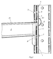
- the shelf consists of vertically arranged uprights 1 in a profiled form. In these uprights 1 are in the desired height horizontally projecting cantilever arms 2 releasably hung on which the goods or pallets are placed.
- the uprights 1 are provided with at least one contact surface 3 running in their longitudinal direction, which has openings 4 arranged at regular intervals.
- the cantilever arm 2 abuts this contact surface 3 with a support surface 5 and furthermore has a claw 6 which projects above the support surface 5 and is essentially rectangular. As a result, the free end 6.1 of the claw 6 extends approximately parallel to the support surface 5. When the cantilever arm 2 is suspended in the upright 1, the claw 6 extends through one of the openings 4 and, with its free end 6.1, engages behind the edge of the opening 4.
- the openings 4 have an elongated shape as seen in the longitudinal direction of the uprights 1, their length essentially corresponding to the length of the free end 6.1 of the claw 6 on the cantilever arm 2. If the opening 4 is longer than the claw 6 itself, the cantilever arm 2 can be mounted directly on the stand 1 without any pivoting movement in a horizontal position. If the opening 4, on the other hand, is slightly smaller than the clear dimension of the claw 6, the cantilever arm 2 must be raised slightly at its end facing away from the stand bar 1, so that the claw can first enter the opening 4 with its free end 6.1. In any case, however, a relatively slight inclination with respect to the horizontal position is sufficient to connect the cantilever arm 2 to the upright 1. Thus, even in confined spaces, additional cantilever arms 2 can be retrofitted to an already existing shelf.
- From the support surface 5 of the cantilever arm 2 also projects at least one pin 7, which is provided for engagement in an adjacent opening 4.
- the distance between the claw 6 and the pin 7 is chosen so that when the cantilever arm 2 is suspended, the edges of the openings extending transversely to the longitudinal direction of the upright 2 form stops on both sides for the claw 6 and the pin 7. Therefore, the suspended cantilever arm 2 cannot be moved in the longitudinal direction of the upright 2 and consequently cannot be detached from the upright. This simple and at the same time secure type of fastening is achieved without any screw connections which are only time-consuming to produce.
- the cantilever arm 2 is formed by a T-shaped profile, one end face of which carries an end plate 8 forming the support surface 5.
- the claw 6 is arranged on the upper edge of the end plate 8 adjoining the support plane 2.1 of the cantilever.
- the free end 6.1 of the claw 6 points in the direction facing away from the pin 7.
- the webs 9 formed between the openings 4 have a width in the range between a quarter and a fifth of the length of the openings 4, as a result of which the smallest possible grid dimension is achieved. Insofar as this is not necessary, the webs 9 can also be made wider, thereby increasing the strength of the upright 1.
- the diameter of the pin 7 should be smaller than the width of the openings 4, since this results in a slight play of the often desired in practice Cantilever arm 2 results in a horizontal plane relative to the upright 1.
- the end plate 8 is provided with two claws 6 and two pins 7, respectively, which are arranged on the left and right symmetrically to the longitudinal axis of the cantilever arm 2.
- a locking bar 10 is provided on the side of the upright 1 facing away from the cantilever arm 2.
- This locking bolt 10 is hooked into the claw 6 and arranged between its free end 6.1 and the upright 1.
- the locking bolt 10 consists of flat material, which has a recess for the passage of the claw 6. With a correspondingly greater length of the locking bolt 10, this is provided with a further recess for the passage of the pin 7 as well.
- the claw 6 can have a free cut 11 on its inside facing the cantilever arm 2, which extends from the free end 6.1 to approximately its center. This free cut 11 forms with the adjacent surface of the upright 1 a receiving groove for the locking bolt 10, but does not affect the position and arrangement of the cantilever arm 2, since the support surface 5 always abuts the contact surface 3 of the upright 1.
- the pin 7 can have a receiving bore for a safety pin at its free end in a manner not shown in the drawing. This ensures that the cantilever arm used in the upright cannot unintentionally loosen.
Landscapes
- Warehouses Or Storage Devices (AREA)
- Assembled Shelves (AREA)
Applications Claiming Priority (2)
| Application Number | Priority Date | Filing Date | Title |
|---|---|---|---|
| DE3941386A DE3941386A1 (de) | 1989-12-15 | 1989-12-15 | Kragarm-regal |
| DE3941386 | 1989-12-15 |
Publications (2)
| Publication Number | Publication Date |
|---|---|
| EP0432372A1 EP0432372A1 (de) | 1991-06-19 |
| EP0432372B1 true EP0432372B1 (de) | 1996-05-15 |
Family
ID=6395494
Family Applications (1)
| Application Number | Title | Priority Date | Filing Date |
|---|---|---|---|
| EP90116844A Expired - Lifetime EP0432372B1 (de) | 1989-12-15 | 1990-09-03 | Kragarm-Regal |
Country Status (3)
| Country | Link |
|---|---|
| EP (1) | EP0432372B1 (enExample) |
| AT (1) | ATE137927T1 (enExample) |
| DE (1) | DE3941386A1 (enExample) |
Families Citing this family (4)
| Publication number | Priority date | Publication date | Assignee | Title |
|---|---|---|---|---|
| DE9111364U1 (de) * | 1991-09-13 | 1991-11-14 | Intra-Profiel Staalbouwtechniek B.V., Velp | Kragarm-Regal |
| DE4133288C2 (de) * | 1991-10-08 | 1999-07-22 | Ohra Regalanlagen Gmbh | Kragarmregal |
| DE29605758U1 (de) * | 1996-03-28 | 1997-04-30 | WM Lagereinrichtungen Vertriebs-GmbH, 76189 Karlsruhe | Kragarmregal |
| CN107517864A (zh) * | 2017-09-26 | 2017-12-29 | 浙江东立生物饲料有限公司 | 一种干湿两用养猪饲料槽 |
Family Cites Families (5)
| Publication number | Priority date | Publication date | Assignee | Title |
|---|---|---|---|---|
| DE7429023U (de) * | 1975-03-20 | Schaefer F Gmbh | Ständerregal für die Lagerung von schwerem und/oder sperrigem Material | |
| FR1324692A (fr) * | 1962-06-07 | 1963-04-19 | Rayonnage démontable | |
| GB992184A (en) * | 1963-04-25 | 1965-05-19 | Church & Company Fittings Ltd | Improvements in brackets |
| DE8128827U1 (de) * | 1981-10-02 | 1982-02-18 | Fritz Schäfer GmbH Fabriken für Lager- und Betriebseinrichtungen, Salchendorf bei Neunkirchen, Kreis Siegen, 5908 Neunkirchen | Bausatz fuer regale |
| GB2150817A (en) * | 1983-12-05 | 1985-07-10 | Paschal John Tobin | Display apparatus |
-
1989
- 1989-12-15 DE DE3941386A patent/DE3941386A1/de active Granted
-
1990
- 1990-09-03 AT AT90116844T patent/ATE137927T1/de not_active IP Right Cessation
- 1990-09-03 EP EP90116844A patent/EP0432372B1/de not_active Expired - Lifetime
Also Published As
| Publication number | Publication date |
|---|---|
| DE3941386C2 (enExample) | 1993-02-11 |
| EP0432372A1 (de) | 1991-06-19 |
| DE3941386A1 (de) | 1991-06-20 |
| ATE137927T1 (de) | 1996-06-15 |
Similar Documents
| Publication | Publication Date | Title |
|---|---|---|
| DE2061369C3 (de) | Leichtmontierbares Regal | |
| DE102010038968B4 (de) | Regal mit Traversen | |
| EP0882660B1 (de) | Regal für Lager- und Kommissionierzwecke | |
| DE1805523A1 (de) | Stuetzanordnung fuer Fachbretter od.dgl. | |
| DE3619262A1 (de) | Transportwagen | |
| DE2856830A1 (de) | Gestell fuer messe-, verkaufsstaende u.dgl. | |
| DE202019103867U1 (de) | Regal | |
| CH630581A5 (en) | Dismountable shelving unit | |
| DE2803023A1 (de) | Rahmengestell | |
| DE3941386C2 (enExample) | ||
| DE69121878T2 (de) | Lagergestell | |
| DE29519639U1 (de) | Regal und Kragarm zu dessen Herstellung | |
| DE2853714A1 (de) | Traggestell | |
| DE9000089U1 (de) | Kragarm mit Sicherungsnase | |
| DE3103983C2 (enExample) | ||
| DE3827574C2 (enExample) | ||
| DE19707892A1 (de) | Kragarmregal | |
| DE4116107C2 (enExample) | ||
| DE7719134U1 (de) | Gestell zur aufnahme von tafelglas | |
| EP0427167B1 (de) | Kragarm-Regal mit Steckverbindung | |
| DE1554472C (de) | Vorrichtung an Regalen oder dgl zum leicht losbaren Verbinden eines Pfostens mit einem Tragstuck | |
| EP4623760A1 (de) | Vorrichtung zur präsentation von gegenständen | |
| DE202017101417U1 (de) | Freitragender Ausstellungsständer | |
| DE2828994A1 (de) | Moebelgestell fuer anbauwaende | |
| DE69803790T2 (de) | Verbindungseinheit und system für balken |
Legal Events
| Date | Code | Title | Description |
|---|---|---|---|
| PUAI | Public reference made under article 153(3) epc to a published international application that has entered the european phase |
Free format text: ORIGINAL CODE: 0009012 |
|
| AK | Designated contracting states |
Kind code of ref document: A1 Designated state(s): AT CH FR LI |
|
| 17P | Request for examination filed |
Effective date: 19911203 |
|
| 17Q | First examination report despatched |
Effective date: 19930429 |
|
| GRAA | (expected) grant |
Free format text: ORIGINAL CODE: 0009210 |
|
| RAP1 | Party data changed (applicant data changed or rights of an application transferred) |
Owner name: JOACHIM LUCHT GMBH |
|
| AK | Designated contracting states |
Kind code of ref document: B1 Designated state(s): AT CH FR LI |
|
| REF | Corresponds to: |
Ref document number: 137927 Country of ref document: AT Date of ref document: 19960615 Kind code of ref document: T |
|
| REG | Reference to a national code |
Ref country code: CH Ref legal event code: NV Representative=s name: ISLER & PEDRAZZINI AG PATENTANWAELTE |
|
| ET | Fr: translation filed | ||
| PLBE | No opposition filed within time limit |
Free format text: ORIGINAL CODE: 0009261 |
|
| STAA | Information on the status of an ep patent application or granted ep patent |
Free format text: STATUS: NO OPPOSITION FILED WITHIN TIME LIMIT |
|
| 26N | No opposition filed | ||
| PG25 | Lapsed in a contracting state [announced via postgrant information from national office to epo] |
Ref country code: FR Effective date: 19970630 |
|
| REG | Reference to a national code |
Ref country code: FR Ref legal event code: ST |
|
| PGFP | Annual fee paid to national office [announced via postgrant information from national office to epo] |
Ref country code: CH Payment date: 19970819 Year of fee payment: 8 |
|
| REG | Reference to a national code |
Ref country code: FR Ref legal event code: ST |
|
| PG25 | Lapsed in a contracting state [announced via postgrant information from national office to epo] |
Ref country code: LI Free format text: LAPSE BECAUSE OF NON-PAYMENT OF DUE FEES Effective date: 19980930 Ref country code: CH Free format text: LAPSE BECAUSE OF NON-PAYMENT OF DUE FEES Effective date: 19980930 |
|
| PGFP | Annual fee paid to national office [announced via postgrant information from national office to epo] |
Ref country code: AT Payment date: 19980930 Year of fee payment: 9 |
|
| REG | Reference to a national code |
Ref country code: CH Ref legal event code: PL |
|
| PG25 | Lapsed in a contracting state [announced via postgrant information from national office to epo] |
Ref country code: AT Free format text: LAPSE BECAUSE OF NON-PAYMENT OF DUE FEES Effective date: 19990903 |