EP0431222A1 - Gasverbrauchsmesseinrichtung - Google Patents
Gasverbrauchsmesseinrichtung Download PDFInfo
- Publication number
- EP0431222A1 EP0431222A1 EP19890312637 EP89312637A EP0431222A1 EP 0431222 A1 EP0431222 A1 EP 0431222A1 EP 19890312637 EP19890312637 EP 19890312637 EP 89312637 A EP89312637 A EP 89312637A EP 0431222 A1 EP0431222 A1 EP 0431222A1
- Authority
- EP
- European Patent Office
- Prior art keywords
- gas
- housing
- module
- openings
- shut
- Prior art date
- Legal status (The legal status is an assumption and is not a legal conclusion. Google has not performed a legal analysis and makes no representation as to the accuracy of the status listed.)
- Granted
Links
Images

Classifications
-
- G—PHYSICS
- G01—MEASURING; TESTING
- G01F—MEASURING VOLUME, VOLUME FLOW, MASS FLOW OR LIQUID LEVEL; METERING BY VOLUME
- G01F15/00—Details of, or accessories for, apparatus of groups G01F1/00 - G01F13/00 insofar as such details or appliances are not adapted to particular types of such apparatus
- G01F15/18—Supports or connecting means for meters
-
- G—PHYSICS
- G01—MEASURING; TESTING
- G01F—MEASURING VOLUME, VOLUME FLOW, MASS FLOW OR LIQUID LEVEL; METERING BY VOLUME
- G01F15/00—Details of, or accessories for, apparatus of groups G01F1/00 - G01F13/00 insofar as such details or appliances are not adapted to particular types of such apparatus
- G01F15/005—Valves
-
- G—PHYSICS
- G01—MEASURING; TESTING
- G01F—MEASURING VOLUME, VOLUME FLOW, MASS FLOW OR LIQUID LEVEL; METERING BY VOLUME
- G01F15/00—Details of, or accessories for, apparatus of groups G01F1/00 - G01F13/00 insofar as such details or appliances are not adapted to particular types of such apparatus
- G01F15/14—Casings, e.g. of special material
-
- G—PHYSICS
- G01—MEASURING; TESTING
- G01F—MEASURING VOLUME, VOLUME FLOW, MASS FLOW OR LIQUID LEVEL; METERING BY VOLUME
- G01F15/00—Details of, or accessories for, apparatus of groups G01F1/00 - G01F13/00 insofar as such details or appliances are not adapted to particular types of such apparatus
- G01F15/18—Supports or connecting means for meters
- G01F15/185—Connecting means, e.g. bypass conduits
Definitions
- the invention relates to a gas consumption measuring device according to the preamble of patent claim 1.
- Gas consumption measuring devices of the type described above for end users usually consist of a gas-tightly closed, provided with an inlet pipe and an outlet pipe, which contains a flow meter with a display device.
- a shut-off valve is arranged in the supply line to the measuring device, with which the gas supply can be shut off if necessary. If necessary, a pressure regulator can be inserted into the supply line in addition to the shut-off valve.
- a secondary meter device for gas is already known, in which a flow meter (gas meter) is combined with a shut-off valve and forms a unit with it.
- a gas consumption meter is known from DE-AS 16 98 463, in which a flow meter (gas consumption meter) with a pressure regulator is housed in a common housing.
- shut-off valve may already be present in an existing gas system, but a flow meter and a pressure regulator must be installed.
- a flow meter and a pressure regulator must be installed.
- the situation is similar for a system with an existing one Pressure regulator and newly installed flow meter with shut-off valve. Either the assembly effort is relatively high or special and therefore expensive device combinations have to be provided for each of these cases.
- the invention has for its object to significantly reduce the required installation effort compared to the previous state in new or re-installations of gas systems and at the same time to create a flexible and adaptable to existing installations uniform and therefore inexpensive device that can be adapted to the respective special requirements in just a few steps can be adjusted.
- the gas consumption measuring device specified in claim 1 is proposed. It is thereby achieved that the components required in addition to the flow meter, such as shut-off valve and pressure regulator, can be accommodated compactly in a common housing and, at the same time, the overall arrangement can be flexibly adapted to the respective local conditions with the least amount of work due to the modular design of these components. In addition, it is achieved that, despite its functional flexibility, the measuring device can be accommodated in a uniform, compact housing, so that the installation work can be precisely planned and carried out with minimal effort because of the constant space requirement. The space required for the storage of the different elements is also reduced to a minimum. The adaptation to the respective requirements can be carried out on the spot with just a few simple steps or centrally with appropriate preliminary planning.
- a flow meter based on the ultrasonic transit time principle is used, as is known per se from EP-A-0 303 255.
- Such an ultrasonic flow meter is very compact and can therefore be combined with the other components in a single housing in a space-saving manner.
- the measuring device can be inserted into an existing line with minimal installation effort.
- the arrangement of the gas inlet and gas outlet openings of the base modules according to the further embodiment according to claim 4 prevents the gas inside the module from reaching the gas inlet opening directly into the gas outlet opening via the wall gap.
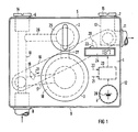
- the housing 1 has a housing 1, which is provided with a first front insertion opening 2 for receiving a shut-off valve, a second front insertion opening 3 for receiving a pressure regulator and a third front insertion opening 4 for accommodating an electrical supply current source is.
- the housing 1 its top 5 has a first closable gas inlet opening 6 and a first closable gas outlet opening 7.
- a second closable gas inlet opening 8 opens out at the bottom 9 of the housing 1 and is connected to the first gas inlet opening 6 via a first connecting pipe 10.
- a second closable gas outlet opening 11 opens out through the side wall 12 of the housing. It is connected to the first gas outlet opening 7 via an angled connecting pipe 13.
- an ultrasonic flow meter 16 is arranged diagonally on the back, which is connected on the inlet side to the pressure regulator base module 18 via a second connecting pipe 17 and on the outlet side to the angled connecting pipe 13 of the gas outlet openings 7, 11.
- the ultrasonic flow meter 16 has two ultrasonic measuring sensors 19, 20 arranged at the ends of its measuring section, which are connected via connecting lines 21, 22 to an electronic evaluation circuit 23, which in turn is connected to a display 24 for the amount of gas used in each case.
- the pressure regulator base module 18 is connected in a gas-conducting manner to the shut-off valve base module 25 via a third connecting tube 26 and this is connected to the first connecting tube 10 via a fourth connecting tube 27.
- the electronic evaluation circuit 23 is fed by a battery 28 arranged in the third frontal insertion opening 4.
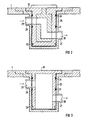
- the gate valve base module 25 is a cup shaped hollow cylinder which is provided with a first gas inlet bore 29 and a first gas outlet bore 30 in different horizontal planes.
- a first O-ring seal 31 is arranged between the two levels, which prevents a gas-conducting creep connection between gas inlet bore 29 and gas outlet bore 30 when the gate valve function module 32 is inserted.
- the third connecting tube 26 is inserted into the first gas inlet bore 29 and the fourth connecting tube 27 is inserted gas-tight into the first gas outlet bore 30.
- the gate valve function module 32 is detachably fastened in the gate valve base module 25 with the aid of a bayonet lock 33.
- the function of the gate valve function module 32 is known and therefore requires no further explanation.
- a second O-ring seal 34 between the first gas inlet bore 29 and the upper edge of the shut-off valve base module ensures the gas seal to the outside.
- Fig. 3 the case is now shown that the gate valve function module 32 is not required. This is the case if there is already a gate valve externally that is to be used further.
- a gate valve blind module 35 of the same geometrical dimension and the same external shape as well as with the same gas inlet and gas outlet bores and in the same horizontal planes arranged first and second O-ring seals 31, 34 and finally with the same Bayonet lock 33 are inserted into the gate valve base module 25 and fastened. In this way it is achieved that the gas consumption measuring device can be used with or without a slide valve function module, which can be replaced by a much cheaper blind module 35 if necessary.
- the pressure regulator function module 36 shown in FIG. 4. This is also known in principle. It consists of a membrane 37, which works against a spring 38 and via an actuation Mechanism 39 acts on a rotary lever 40 which regulates the gas inlet via a valve 41 as a function of the pressure prevailing in the pressure chamber 42.
- the pressure regulator function module is inserted and held in the pressure regulator base module 18 in the same way with the aid of a bayonet lock 33 as the gate valve function module 32 already described. It has a second gas inlet bore 43 and a second gas outlet bore 44.
- Both bores lie in different horizontal planes and are separated from each other in a gas-tight manner by a third O-ring seal 45.
- a fourth O-ring seal 46 provides the gas seal to the outside. If a pressure regulator is already present in an existing gas installation, a pressure regulator dummy module 48 with otherwise the same geometric dimensions as the pressure regulator function module 36 can also be inserted into the pressure regulator in this case, as already described for the gate valve function module 36 -Base module 18 inserted and attached.
- the measuring device can be adapted to local conditions with great flexibility and simple means.
Abstract
Description
- Die Erfindung betrifft eine Gasverbrauchsmeßeinrichtung nach dem Oberbegriff des Patentanspruchs 1.
- Gasverbrauchsmeßeinrichtungen der vorbeschriebenen Art für Endverbraucher bestehen üblicherweise aus einem gasdicht verschlossenen, mit einem Eintrittsrohr und einem Austrittsrohr versehenen Kessel, der einen Durchflußmengenmesser mit Anzeigevorrichtung enthält. In der Versorgungsleitung zur Meßeinrichtung ist ein Absperrventil angeordnet, mit dem die Gaszufuhr im Bedarfsfall gesperrt werden kann. Erforderlichenfalls kann zusätzlich zum Absperrventil ein Druckregler in die Zuleitung eingefügt werden.
- Aus der DE-PS 803 492 ist auch bereits eine Nebenzähler-Einrichtung für Gas bekannt, bei der ein Durchflußmengenmesser (Gaszähler) mit einem Absperrventil kombiniert ist und mit diesem eine Einheit bildet. Darüber hinaus ist aus der DE-AS 16 98 463 ein Gas-Verbrauchsmesser bekannt, bei dem ein Durchflußmengenmesser (Gas-Verbrauchsmesser) mit einem Druckregler in einem gemeinsamen Gehäuse untergebracht ist.
- Diesen bekannten Einrichtungen ist der Nachteil gemeinsam, daß bei deren Installation in eine vorhandene Gasanlage mehr oder weniger umfangreiche Installationsarbeiten mit entsprechendem Kostenaufwand erforderlich sind. So kann beispielsweise der Fall eintreten, daß in einer vorhandenen Gasanlage bereits ein Absperrventil vorhanden ist, aber ein Durchflußmengenmesser und ein Druckregler installiert werden müssen. Dazu ist es erforderlich, daß entweder die beiden Elemente jedes für sich in die Anlage eingebaut werden oder beispielsweise eine Anordnung verwendet wird, wie sie aus der DE-AS 16 98 463 bekannt ist. Ähnlich verhält es sich etwa bei einer Anlage mit vorhandenem Druckregler und neu zu installierendem Durchflußmengenmesser mit Absperrventil. Entweder ist dabei der Montageaufwand relativ hoch oder es müssen für jeden dieser Fälle spezielle und daher kostspielige Gerätekombinationen bereitgestellt werden.
- Der Erfindung liegt die Aufgabe zugrunde, bei Neu- oder Nachinstallationen von Gasanlagen den erforderlichen Installationsaufwand gegenüber dem bisherigen Zustand deutlich zu verringern und gleichzeitig eine flexibel an vorhandene Installationen anpaßbare einheitliche und daher preiswerte Einrichtung zu schaffen, die sich mit wenigen Handgriffen an die jeweiligen speziellen Anforderungen anpassen läßt.
- Zur Lösung dieser Aufgabe wird die im Patentanspruch 1 angegebene Gasverbrauchsmeßeinrichtung vorgeschlagen. Dadurch ist erreicht, daß die neben dem Durchflußmengenmesser noch erforderlichen Bauelemente, wie Absperrventil und Druckregler, in einem gemeinsamen Gehäuse kompakt untergebracht werden können und gleichzeitig durch die modulare Gestaltung dieser Bauelemente die Gesamtanordnung mit geringstem Arbeitsaufwand flexibel an die jeweiligen örtlichen Verhältnisse angepaßt werden kann. Darüber hinaus ist erreicht, daß sich die Meßeinrichtung trotz ihrer funktionalen Flexibilität in einem einheitlichen kompakten Gehäuse unterbringen läßt, so daß die Installationsarbeiten wegen des stets gleichbleibenden Raumbedarfs exakt vorgeplant und mit minimalem Aufwand durchgeführt werden können. Auch der Raumbedarf für die Lagerhaltung der unterschiedlichen Elemente reduziert sich auf ein Miminum. Die Anpassung an die jeweiligen Erfordernisse kann sowohl an Ort und Stelle mit wenigen Handgriffen als auch zentral bei entsprechender Vorplanung durchgeführt werden.
- In einer Weiterbildung der Erfindung gemäß Patentanspruch 2 ist ein Durchflußmengenmesser nach dem Ultraschall-Laufzeitprinzip verwendet, wie er etwa aus der EP-A-0 303 255 an sich bekannt ist. Ein solcher Ultraschall-Durchflußmengenmesser ist sehr kompakt und läßt sich daher besonders gut mit den übrigen Bauelementen in einem einzigen Gehäuse raumsparend kombinieren.
- Durch die weitere besonders vorteilhafte Ausbildung gemäß Patentanspruch 3 ist erreicht, daß sich die Meßeinrichtung mit minimalem Installationsaufwand in eine vorhandene Leitungsführung einfügen läßt.
- Durch die Anordnung der Gaseintritts- und Gasaustrittsöffnungen der Basismodule gemäß der weiteren Ausbildung nach Patentanspruch 4 ist vermieden, daß das Gas innerhalb des Moduls von der Gaseintrittsöffnung über den Wandspalt unmittelbar in die Gasaustrittsöffnung gelangen kann.
- Weitere Einzelheiten der Erfindung werden anhand eines Ausführungsbeispiels im folgenden näher erläutert. Darin zeigen:
- Fig. 1 die erfindungsgemäß modular aufgebaute Gasverbrauchsmeßeinrichtung in einer räumlichen Übersichtsdarstellung;
- Fig. 2 die Prinzipdarstellung eines modular gestalteten Absperrventils;
- Fig. 3 ein anstelle des Absperrventils eingesetztes Blindmodul;
- Fig. 4 einen modular gestalteten Gasdruckregler als Prinzipdarstellung, und
- Fig. 5 ein anstelle des Gasdruckreglers eingesetztes Blindmodul.
- Die in Fig. 1 dargestellte modular aufgebaute Gasverbrauchsmeßeinrichtung besitzt ein Gehäuse 1, welches mit einer ersten frontalen Einschuböffnung 2 für die Aufnahme eines Absperrventils, einer zweiten frontalen Einschuböffnung 3 für die Aufnahme eines Druckreglers sowie einer dritten frontalen Einschuböffnung 4 für die Unterbringung einer elektrischen Speisestromquelle versehen ist. Außerdem besitzt das Gehäuse 1 an seiner Oberseite 5 eine erste verschließbare Gaseinlaßöffnung 6 und eine erste verschließbare Gasauslaßöffnung 7. Eine zweite verschließbare Gaseinlaßöffnung 8 mündet an der Unterseite 9 des Gehäuses 1 nach außen und ist über ein erstes Verbindungsrohr 10 mit der ersten Gaseinlaßöffnung 6 verbunden. Eine zweite verschließbare Gasauslaßöffnung 11 mündet durch die Seitenwand 12 des Gehäuses nach außen. Sie ist mit der ersten Gasauslaßöffnung 7 über ein abgewinkeltes Verbindungsrohr 13 verbunden. Es ist natürlich auch möglich, weitere miteinander verbundene Gaseinlaß- und Gasauslaßöffnungen nach Belieben anzuordnen, und bis auf die jeweils benutzten mit Hilfe von Schraubkappen 14, 15 gasdicht zu verschließen und zu plombieren. Die nicht verschlossenen Öffnungen 8, 11 können auf nicht dargestellte Weise an die Gaszuleitung bzw. die Gasableitung angeschlossen werden.
- Im Innern des Gehäuses 1 ist rückseitig ein Ultraschall -Durchflußmengenmesser 16 diagonal angeordnet, der einlaßseitig über ein zweites Verbindungsrohr 17 mit dem Druckregler-Basismodul 18 und auslaßseitig mit dem abgewinkelten Verbindungsrohr 13 der Gasauslaßöffnungen 7, 11 verbunden ist. Der Ultraschall-Durchflußmengenmesser 16 besitzt zwei an den Enden seiner Meßstrecke angeordnete Ultraschall-Meßsensoren 19, 20, die über Verbindungsleitungen 21, 22 mit einer elektronischen Auswerteschaltung 23 verbunden sind, die ihrerseits an ein Anzeigedisplay 24 für die jeweils verbrauchte Gasmenge angeschlossen ist. Das Druckregler-Basismodul 18 ist über ein drittes Verbindungsrohr 26 mit dem Absperrventil-Basismodul 25 und dieses über ein viertes Verbindungsrohr 27 mit dem ersten Verbindungsrohr 10 gasleitend verbunden. Die elektronische Auswerteschaltung 23 wird von einer in der dritten frontalen Einschuböffnung 4 angeordneten Batterie 28 gespeist.
- In Fig. 2 ist nun die erste frontale Einschuböffnung 2 mit dem Absperrschieber-Basismodul 25 und dem eingeführtem Absperrschieber-Funktionsmodul 32 in einem Längsschnitt schematisch dargestellt. Das Absperrschieber-Basismodul 25 ist ein becher förmiger Hohlzylinder, der mit einer ersten Gaseinlaßbohrung 29 und einer ersten Gasauslaßbohrung 30 in unterschiedlichen horizontalen Ebenen versehen ist. Zwischen den beiden Ebenen ist eine erste O-Ringdichtung 31 angeordnet, die verhindert, daß bei eingesetztem Absperrschieber-Funktionsmodul 32 zwischen Gaseinlaßbohrung 29 und Gasauslaßbohrung 30 eine gasleitende Kriechverbindung besteht. In die erste Gaseinlaßbohrung 29 ist das dritte Verbindungsrohr 26 und in die erste Gasauslaßbohrung 30 ist das vierte Verbindungsrohr 27 gasdicht eingelassen. Das Absperrschieber-Funktionsmodul 32 ist im Absperrschieber-Basismodul 25 mit Hilfe eines Bajonettverschlusses 33 lösbar befestigt. Das Absperrschieber-Funktionsmodul 32 ist in seiner Funktion bekannt und bedarf daher keiner näheren Erläuterung. Eine zweite O-Ringdichtung 34 zwischen der ersten Gaseinlaßbohrung 29 und der Oberkante des Absperrventil-Basismoduls sorgt für die Gasabdichtung nach außen.
- In Fig. 3 ist nun der Fall dargestellt, daß das Absperrschieber-Funktionsmodul 32 nicht benötigt wird. Dies ist dann der Fall, wenn bereits extern ein Absperrschieber vorhanden ist, der weiterbenutzt werden soll. In diesem Fall kann anstelle des Absperrschieber-Funktionsmoduls 32 ein Absperrschieber-Blindmodul 35 gleicher geometrischer Abmessung und gleicher äußerer Form sowie mit gleichen Gaseinlaß- und Gasauslaßbohrungen und in den gleichen horizontalen Ebenen angeordneten ersten und zweiten O-Ringdichtungen 31, 34 und schließlich mit dem gleichen Bajonettverschluß 33 in das Absperrschieber-Basismodul 25 eingeführt und befestigt werden. Auf diese Weise ist erreicht, daß die Gasverbrauchsmeßeinrichtung mit oder ohne Absperrschieber-Funktionsmodul benutzt werden kann, welches im Bedarfsfall durch ein wesentlich preisgünstigeres Blindmodul 35 ersetzt werden kann. Bei einer Modernisierung der Installation besteht dann jederzeit die Möglichkeit, das Blindmodul 35 gegen ein Funktionsmodul 32 auszutauschen. Das gleiche gilt für das in Fig. 4 dargestellte Druckregler-Funktionsmodul 36. Auch dieses ist im Prinzip bekannt. Es besteht aus einer Membran 37, die gegen eine Feder 38 arbeitet und über einen Betätigungs mechanismus 39 auf einen Drehhebel 40 wirkt, der über ein Ventil 41 den Gaseinlaß in Abhängigkeit von dem in der Druckkammer 42 herrschenden Druck regelt. Das Druckregler-Funktionsmodul ist in das Druckregler-Basismodul 18 in gleicher Weise mit Hilfe eines Bajonettverschlusses 33 eingesetzt und gehaltert wie das bereits beschriebene Absperrschieber-Funktionsmodul 32. Es besitzt eine zweite Gaseinlaßbohrung 43 und eine zweite Gasauslaßbohrung 44. Beide Bohrungen liegen in unterschiedlichen horizontalen Ebenen und sind durch eine dritte O-Ringdichtung 45 gasdicht voneinander getrennt. Eine vierte O-Ringdichtung 46 sorgt für die Gasabdichtung nach außen. Falls in einer vorhandenen Gasinstalation bereits ein Druckregler vorhanden ist, kann auch in diesem Fall, wie bereits beim Absperrschieber-Funktionsmodul beschrieben, anstelle des Druckregler-Funktionsmoduls 36 ein Druckregler-Blindmodul 48 mit ansonsten gleicher geometrischer Abmessung wie das Druckregler-Funktionsmodul 36 in das Druckregler-Basismodul 18 eingeführt und befestigt werden.
- Durch die verschiedenen Möglichkeiten sowohl hinsichtlich des Anschlusses der Gasleitungen an den in unterschiedlichen Richtungen angeordnete Gaseinlaß- und Gasauslaßöffnungen, von denen die jeweils nicht benutzten auf einfache Weise mit Hilfe von Schraubkappen geschlossen werden können, und die weitere Möglichkeit der Anpassung an unterschiedliche Gasinstallationen durch Einfügen von Funktionsmodulen oder Blindmodulen ist die Meßeinrichtung mit großer Flexibilität und einfachen Mitteln an die örtlichen Gegebenheiten anpaßbar.
Claims (4)
Priority Applications (8)
| Application Number | Priority Date | Filing Date | Title |
|---|---|---|---|
| EP89312637A EP0431222B1 (de) | 1989-12-04 | 1989-12-04 | Gasverbrauchsmesseinrichtung |
| ES89312637T ES2052936T3 (es) | 1989-12-04 | 1989-12-04 | Dispositivo de medicion del consumo de gas. |
| DE58907586T DE58907586D1 (de) | 1989-12-04 | 1989-12-04 | Gasverbrauchsmesseinrichtung. |
| AT8989312637T ATE105081T1 (de) | 1989-12-04 | 1989-12-04 | Gasverbrauchsmesseinrichtung. |
| JP2326090A JPH03186720A (ja) | 1989-12-04 | 1990-11-29 | ガス消費量測定装置 |
| CA002031323A CA2031323A1 (en) | 1989-12-04 | 1990-12-03 | Gas consumption measuring device |
| KR1019900019857A KR910012677A (ko) | 1989-12-04 | 1990-12-04 | 가스소비량 측정장치 |
| US07/939,959 US5257538A (en) | 1989-04-12 | 1992-09-04 | Gas consumption measuring device |
Applications Claiming Priority (1)
| Application Number | Priority Date | Filing Date | Title |
|---|---|---|---|
| EP89312637A EP0431222B1 (de) | 1989-12-04 | 1989-12-04 | Gasverbrauchsmesseinrichtung |
Publications (2)
| Publication Number | Publication Date |
|---|---|
| EP0431222A1 true EP0431222A1 (de) | 1991-06-12 |
| EP0431222B1 EP0431222B1 (de) | 1994-04-27 |
Family
ID=8202872
Family Applications (1)
| Application Number | Title | Priority Date | Filing Date |
|---|---|---|---|
| EP89312637A Expired - Lifetime EP0431222B1 (de) | 1989-04-12 | 1989-12-04 | Gasverbrauchsmesseinrichtung |
Country Status (7)
| Country | Link |
|---|---|
| EP (1) | EP0431222B1 (de) |
| JP (1) | JPH03186720A (de) |
| KR (1) | KR910012677A (de) |
| AT (1) | ATE105081T1 (de) |
| CA (1) | CA2031323A1 (de) |
| DE (1) | DE58907586D1 (de) |
| ES (1) | ES2052936T3 (de) |
Cited By (9)
| Publication number | Priority date | Publication date | Assignee | Title |
|---|---|---|---|---|
| DE4322696A1 (de) * | 1993-07-07 | 1995-01-12 | Harald Potera | Montage-Baustein zur Aufnahme von Absperreinrichtungen und Wasserzählern |
| FR2736430A1 (fr) * | 1995-07-05 | 1997-01-10 | Schlumberger Ind Sa | Organe de coupure antifraude pour compteur de gaz et compteur de gaz equipe d'un tel organe de coupure |
| WO1997014018A1 (de) * | 1995-10-10 | 1997-04-17 | Kamo Wärmetechnische Gesellschaft Mbh | Montagebaustein für die sanitärinstallation und verfahren zur herstellung desselben |
| GB2319342A (en) * | 1996-11-15 | 1998-05-20 | Siemens Measurements Ltd | Gas meter with add-on module |
| FR2776380A1 (fr) * | 1998-03-19 | 1999-09-24 | Mecelec Ind | Coffret hors sol de raccordement a un reseau de gaz |
| ITPD20100135A1 (it) * | 2010-04-28 | 2011-10-29 | Metersit Srl | Apparecchio contatore per gas perfezionato |
| RU2658033C2 (ru) * | 2013-09-02 | 2018-06-19 | Джонсон Электрик С.А. | Газовый запорный клапан |
| DE102017004450A1 (de) * | 2017-05-09 | 2018-11-15 | Diehl Metering Gmbh | Anordnung zum Einbau in ein Fluidleitungsnetz |
| EP2029975B2 (de) † | 2006-05-25 | 2019-06-12 | ZENNER GAS S.r.l. | Verfahren und vorrichtung zum betreiben eines mit einem gasmessgerät verbundenen elektromagnetischen ventils |
Families Citing this family (1)
| Publication number | Priority date | Publication date | Assignee | Title |
|---|---|---|---|---|
| US5567875A (en) * | 1995-05-05 | 1996-10-22 | Schlumberger Industries, Inc. | Modular gas meter assembly and associated manifold |
Citations (7)
| Publication number | Priority date | Publication date | Assignee | Title |
|---|---|---|---|---|
| DE612278C (de) * | 1935-04-17 | Wilhelm Kleisser | Anschlussvorrichtung fuer Gasmesser | |
| DE803492C (de) * | 1950-02-11 | 1951-06-11 | Elster & Co Akt Ges | Nebenzaehler-Einrichtung fuer Gas |
| DE1698463A1 (de) * | 1962-04-14 | 1970-12-10 | Yazaki Meter Co Ltd | Gas-Entnahmeeinrichtung |
| CA991441A (en) * | 1974-01-22 | 1976-06-22 | Julio Bizecki | Gas meter support bracket |
| EP0243294A1 (de) * | 1986-02-27 | 1987-10-28 | Siemens Aktiengesellschaft | Durchflussmessanordnung |
| EP0303255A1 (de) * | 1987-08-10 | 1989-02-15 | Siemens Aktiengesellschaft | Ultraschall-Durchflussmesseinrichtung |
| GB2215758A (en) * | 1988-03-22 | 1989-09-27 | David George Reynel | Mounting means for water meter and/or stop tap |
-
1989
- 1989-12-04 ES ES89312637T patent/ES2052936T3/es not_active Expired - Lifetime
- 1989-12-04 AT AT8989312637T patent/ATE105081T1/de not_active IP Right Cessation
- 1989-12-04 DE DE58907586T patent/DE58907586D1/de not_active Expired - Fee Related
- 1989-12-04 EP EP89312637A patent/EP0431222B1/de not_active Expired - Lifetime
-
1990
- 1990-11-29 JP JP2326090A patent/JPH03186720A/ja active Pending
- 1990-12-03 CA CA002031323A patent/CA2031323A1/en not_active Abandoned
- 1990-12-04 KR KR1019900019857A patent/KR910012677A/ko not_active Application Discontinuation
Patent Citations (7)
| Publication number | Priority date | Publication date | Assignee | Title |
|---|---|---|---|---|
| DE612278C (de) * | 1935-04-17 | Wilhelm Kleisser | Anschlussvorrichtung fuer Gasmesser | |
| DE803492C (de) * | 1950-02-11 | 1951-06-11 | Elster & Co Akt Ges | Nebenzaehler-Einrichtung fuer Gas |
| DE1698463A1 (de) * | 1962-04-14 | 1970-12-10 | Yazaki Meter Co Ltd | Gas-Entnahmeeinrichtung |
| CA991441A (en) * | 1974-01-22 | 1976-06-22 | Julio Bizecki | Gas meter support bracket |
| EP0243294A1 (de) * | 1986-02-27 | 1987-10-28 | Siemens Aktiengesellschaft | Durchflussmessanordnung |
| EP0303255A1 (de) * | 1987-08-10 | 1989-02-15 | Siemens Aktiengesellschaft | Ultraschall-Durchflussmesseinrichtung |
| GB2215758A (en) * | 1988-03-22 | 1989-09-27 | David George Reynel | Mounting means for water meter and/or stop tap |
Cited By (16)
| Publication number | Priority date | Publication date | Assignee | Title |
|---|---|---|---|---|
| DE4322696C2 (de) * | 1993-07-07 | 2001-05-17 | Harald Potera | Montage-Baustein zur Aufnahme von Absperreinrichtungen und Wasserzählern |
| DE4322696A1 (de) * | 1993-07-07 | 1995-01-12 | Harald Potera | Montage-Baustein zur Aufnahme von Absperreinrichtungen und Wasserzählern |
| FR2736430A1 (fr) * | 1995-07-05 | 1997-01-10 | Schlumberger Ind Sa | Organe de coupure antifraude pour compteur de gaz et compteur de gaz equipe d'un tel organe de coupure |
| WO1997002471A1 (fr) * | 1995-07-05 | 1997-01-23 | Schlumberger Industries S.A. | Organe de coupure antifraude pour compteur de gaz et compteur de gaz equipe d'un tel organe de coupure |
| US6056002A (en) * | 1995-10-10 | 2000-05-02 | Morlok; Ulrich | Assembling module for sanitary plumbing and method for manufacturing same |
| WO1997014018A1 (de) * | 1995-10-10 | 1997-04-17 | Kamo Wärmetechnische Gesellschaft Mbh | Montagebaustein für die sanitärinstallation und verfahren zur herstellung desselben |
| EP0843288A3 (de) * | 1996-11-15 | 2000-07-05 | Siemens Measurements Limited | Verbesserungen für und in Bezug auf Gaszähler |
| EP0843288A2 (de) * | 1996-11-15 | 1998-05-20 | Siemens Measurements Limited | Verbesserungen für und in Bezug auf modulare Gaszähler |
| GB2319342B (en) * | 1996-11-15 | 2000-12-13 | Siemens Measurements Ltd | Improvements in or relating to gas meters |
| GB2319342A (en) * | 1996-11-15 | 1998-05-20 | Siemens Measurements Ltd | Gas meter with add-on module |
| FR2776380A1 (fr) * | 1998-03-19 | 1999-09-24 | Mecelec Ind | Coffret hors sol de raccordement a un reseau de gaz |
| EP2029975B2 (de) † | 2006-05-25 | 2019-06-12 | ZENNER GAS S.r.l. | Verfahren und vorrichtung zum betreiben eines mit einem gasmessgerät verbundenen elektromagnetischen ventils |
| ITPD20100135A1 (it) * | 2010-04-28 | 2011-10-29 | Metersit Srl | Apparecchio contatore per gas perfezionato |
| RU2658033C2 (ru) * | 2013-09-02 | 2018-06-19 | Джонсон Электрик С.А. | Газовый запорный клапан |
| DE102017004450A1 (de) * | 2017-05-09 | 2018-11-15 | Diehl Metering Gmbh | Anordnung zum Einbau in ein Fluidleitungsnetz |
| US10781577B2 (en) | 2017-05-09 | 2020-09-22 | Diehl Metering Gmbh | Arrangement for installation in a fluid line network, connector and fluid meter |
Also Published As
| Publication number | Publication date |
|---|---|
| ES2052936T3 (es) | 1994-07-16 |
| EP0431222B1 (de) | 1994-04-27 |
| ATE105081T1 (de) | 1994-05-15 |
| CA2031323A1 (en) | 1991-06-05 |
| JPH03186720A (ja) | 1991-08-14 |
| DE58907586D1 (de) | 1994-06-01 |
| KR910012677A (ko) | 1991-08-08 |
Similar Documents
| Publication | Publication Date | Title |
|---|---|---|
| EP0431222B1 (de) | Gasverbrauchsmesseinrichtung | |
| EP1835264A2 (de) | Nichteigensicher gespeistes Messgerät | |
| EP1364261B2 (de) | System zur automatisierten behandlung von fluiden, mit aneinanderreihbaren, austauschbaren prozessmodulen | |
| DE69818177T2 (de) | Rohrverbindung für einen unter Druck stehenden Apparat | |
| EP0909898B1 (de) | Druckluftwartungseinheit | |
| DE3711754A1 (de) | Explosionsgeschuetztes magnetisch-induktives durchflussmessgeraet | |
| EP1174781A2 (de) | Einrichtung zur Signalübertragung | |
| DE2900329C2 (de) | Explosionsgeschützte Schalteinrichtung | |
| DE3714196A1 (de) | Versorgungsbalken fuer die intensivpflege | |
| DE102007008268B4 (de) | Prüfstand und Prüfverfahren für einen Brennstoffzellenstapel | |
| DE8224198U1 (de) | Vorrichtung zur verhinderung und aufloesung von kalkansatz in wasserfuehrenden anlagen | |
| DE102014004618B4 (de) | Kalibrierstation mit externer Gasführungsschiene | |
| DE102006029743A1 (de) | Brennstoffzellensystem | |
| EP1086313A1 (de) | Wartungsvorrichtung für druckluftanlagen | |
| EP2267462B1 (de) | Adapterbaugruppe | |
| EP2217811A1 (de) | Baukastenartiges elektrisches installationssystem | |
| DE60204505T2 (de) | Abgedichtetes elektrisches Schaltgehäuse | |
| EP0424817B1 (de) | Im wesentlichen kubischer Steckerbauteil bzw. Gerät | |
| EP2063131B1 (de) | Schaltschrank mit interner Ventilanordnung | |
| DE3012743A1 (de) | Geraet der schutzart eigensicherheit | |
| DE102018129208A1 (de) | Verteilerelement für ein Gasabschaltventil für den Einbau in Industriegaszähler | |
| EP1293308A1 (de) | Verfahren und Vorrichtung zum Schutz einer explosionsgefährdeten Umgebung durch elektronische Bauteile mittels Luftaustausch | |
| EP0777816A1 (de) | Untertägiger energiezug | |
| DE2848033A1 (de) | Baugruppe zur aufnahme elektronischer geraete | |
| DE8305869U1 (de) | Lüftereinschub |
Legal Events
| Date | Code | Title | Description |
|---|---|---|---|
| PUAI | Public reference made under article 153(3) epc to a published international application that has entered the european phase |
Free format text: ORIGINAL CODE: 0009012 |
|
| 17P | Request for examination filed |
Effective date: 19901026 |
|
| AK | Designated contracting states |
Kind code of ref document: A1 Designated state(s): AT BE CH DE ES FR GB GR IT LI NL SE |
|
| 17Q | First examination report despatched |
Effective date: 19930514 |
|
| RAP3 | Party data changed (applicant data changed or rights of an application transferred) |
Owner name: SIEMENS MEASUREMENTS LIMITED Owner name: SIEMENS AKTIENGESELLSCHAFT |
|
| GRAA | (expected) grant |
Free format text: ORIGINAL CODE: 0009210 |
|
| AK | Designated contracting states |
Kind code of ref document: B1 Designated state(s): AT BE CH DE ES FR GB GR IT LI NL SE |
|
| PG25 | Lapsed in a contracting state [announced via postgrant information from national office to epo] |
Ref country code: GR Free format text: LAPSE BECAUSE OF FAILURE TO SUBMIT A TRANSLATION OF THE DESCRIPTION OR TO PAY THE FEE WITHIN THE PRESCRIBED TIME-LIMIT Effective date: 19940427 |
|
| REF | Corresponds to: |
Ref document number: 105081 Country of ref document: AT Date of ref document: 19940515 Kind code of ref document: T |
|
| REF | Corresponds to: |
Ref document number: 58907586 Country of ref document: DE Date of ref document: 19940601 |
|
| REG | Reference to a national code |
Ref country code: ES Ref legal event code: FG2A Ref document number: 2052936 Country of ref document: ES Kind code of ref document: T3 |
|
| ITF | It: translation for a ep patent filed |
Owner name: STUDIO JAUMANN |
|
| ET | Fr: translation filed | ||
| GBT | Gb: translation of ep patent filed (gb section 77(6)(a)/1977) |
Effective date: 19940805 |
|
| EAL | Se: european patent in force in sweden |
Ref document number: 89312637.5 |
|
| PLBE | No opposition filed within time limit |
Free format text: ORIGINAL CODE: 0009261 |
|
| STAA | Information on the status of an ep patent application or granted ep patent |
Free format text: STATUS: NO OPPOSITION FILED WITHIN TIME LIMIT |
|
| 26N | No opposition filed | ||
| PGFP | Annual fee paid to national office [announced via postgrant information from national office to epo] |
Ref country code: CH Payment date: 19960320 Year of fee payment: 7 |
|
| PGFP | Annual fee paid to national office [announced via postgrant information from national office to epo] |
Ref country code: AT Payment date: 19961127 Year of fee payment: 8 |
|
| PGFP | Annual fee paid to national office [announced via postgrant information from national office to epo] |
Ref country code: SE Payment date: 19961210 Year of fee payment: 8 |
|
| PGFP | Annual fee paid to national office [announced via postgrant information from national office to epo] |
Ref country code: ES Payment date: 19961212 Year of fee payment: 8 |
|
| PGFP | Annual fee paid to national office [announced via postgrant information from national office to epo] |
Ref country code: NL Payment date: 19961217 Year of fee payment: 8 |
|
| PGFP | Annual fee paid to national office [announced via postgrant information from national office to epo] |
Ref country code: BE Payment date: 19961220 Year of fee payment: 8 |
|
| PG25 | Lapsed in a contracting state [announced via postgrant information from national office to epo] |
Ref country code: LI Effective date: 19961231 Ref country code: CH Effective date: 19961231 |
|
| REG | Reference to a national code |
Ref country code: CH Ref legal event code: PL |
|
| PG25 | Lapsed in a contracting state [announced via postgrant information from national office to epo] |
Ref country code: AT Free format text: LAPSE BECAUSE OF NON-PAYMENT OF DUE FEES Effective date: 19971204 |
|
| PG25 | Lapsed in a contracting state [announced via postgrant information from national office to epo] |
Ref country code: SE Free format text: LAPSE BECAUSE OF NON-PAYMENT OF DUE FEES Effective date: 19971205 Ref country code: ES Free format text: LAPSE BECAUSE OF THE APPLICANT RENOUNCES Effective date: 19971205 |
|
| PG25 | Lapsed in a contracting state [announced via postgrant information from national office to epo] |
Ref country code: BE Free format text: LAPSE BECAUSE OF NON-PAYMENT OF DUE FEES Effective date: 19971231 |
|
| BERE | Be: lapsed |
Owner name: SIEMENS MEASUREMENTS LTD Effective date: 19971231 Owner name: SIEMENS A.G. Effective date: 19971231 |
|
| PG25 | Lapsed in a contracting state [announced via postgrant information from national office to epo] |
Ref country code: NL Free format text: LAPSE BECAUSE OF NON-PAYMENT OF DUE FEES Effective date: 19980701 |
|
| NLV4 | Nl: lapsed or anulled due to non-payment of the annual fee |
Effective date: 19980701 |
|
| EUG | Se: european patent has lapsed |
Ref document number: 89312637.5 |
|
| PGFP | Annual fee paid to national office [announced via postgrant information from national office to epo] |
Ref country code: DE Payment date: 20010219 Year of fee payment: 12 |
|
| REG | Reference to a national code |
Ref country code: ES Ref legal event code: FD2A Effective date: 20010402 |
|
| PGFP | Annual fee paid to national office [announced via postgrant information from national office to epo] |
Ref country code: FR Payment date: 20011204 Year of fee payment: 13 |
|
| PGFP | Annual fee paid to national office [announced via postgrant information from national office to epo] |
Ref country code: GB Payment date: 20011206 Year of fee payment: 13 |
|
| REG | Reference to a national code |
Ref country code: GB Ref legal event code: IF02 |
|
| PG25 | Lapsed in a contracting state [announced via postgrant information from national office to epo] |
Ref country code: DE Free format text: LAPSE BECAUSE OF NON-PAYMENT OF DUE FEES Effective date: 20020702 |
|
| PG25 | Lapsed in a contracting state [announced via postgrant information from national office to epo] |
Ref country code: GB Free format text: LAPSE BECAUSE OF NON-PAYMENT OF DUE FEES Effective date: 20021204 |
|
| GBPC | Gb: european patent ceased through non-payment of renewal fee | ||
| PG25 | Lapsed in a contracting state [announced via postgrant information from national office to epo] |
Ref country code: FR Free format text: LAPSE BECAUSE OF NON-PAYMENT OF DUE FEES Effective date: 20030901 |
|
| REG | Reference to a national code |
Ref country code: FR Ref legal event code: ST |
|
| PG25 | Lapsed in a contracting state [announced via postgrant information from national office to epo] |
Ref country code: IT Free format text: LAPSE BECAUSE OF NON-PAYMENT OF DUE FEES Effective date: 20051204 |