EP0428983A2 - Partikelentfernung von Oberflächen durch Druckwechsel - Google Patents
Partikelentfernung von Oberflächen durch Druckwechsel Download PDFInfo
- Publication number
- EP0428983A2 EP0428983A2 EP90121717A EP90121717A EP0428983A2 EP 0428983 A2 EP0428983 A2 EP 0428983A2 EP 90121717 A EP90121717 A EP 90121717A EP 90121717 A EP90121717 A EP 90121717A EP 0428983 A2 EP0428983 A2 EP 0428983A2
- Authority
- EP
- European Patent Office
- Prior art keywords
- cleaning liquid
- pressure
- gas
- article
- pressure vessel
- Prior art date
- Legal status (The legal status is an assumption and is not a legal conclusion. Google has not performed a legal analysis and makes no representation as to the accuracy of the status listed.)
- Withdrawn
Links
Images

Classifications
-
- H—ELECTRICITY
- H10—SEMICONDUCTOR DEVICES; ELECTRIC SOLID-STATE DEVICES NOT OTHERWISE PROVIDED FOR
- H10P—GENERIC PROCESSES OR APPARATUS FOR THE MANUFACTURE OR TREATMENT OF DEVICES COVERED BY CLASS H10
- H10P72/00—Handling or holding of wafers, substrates or devices during manufacture or treatment thereof
- H10P72/04—Apparatus for manufacture or treatment
- H10P72/0402—Apparatus for fluid treatment
- H10P72/0406—Apparatus for fluid treatment for cleaning followed by drying, rinsing, stripping, blasting or the like
- H10P72/0411—Apparatus for fluid treatment for cleaning followed by drying, rinsing, stripping, blasting or the like for wet cleaning or washing
- H10P72/0416—Apparatus for fluid treatment for cleaning followed by drying, rinsing, stripping, blasting or the like for wet cleaning or washing with the semiconductor substrates being dipped in baths or vessels
-
- H—ELECTRICITY
- H10—SEMICONDUCTOR DEVICES; ELECTRIC SOLID-STATE DEVICES NOT OTHERWISE PROVIDED FOR
- H10P—GENERIC PROCESSES OR APPARATUS FOR THE MANUFACTURE OR TREATMENT OF DEVICES COVERED BY CLASS H10
- H10P72/00—Handling or holding of wafers, substrates or devices during manufacture or treatment thereof
- H10P72/04—Apparatus for manufacture or treatment
- H10P72/0402—Apparatus for fluid treatment
- H10P72/0406—Apparatus for fluid treatment for cleaning followed by drying, rinsing, stripping, blasting or the like
- H10P72/0411—Apparatus for fluid treatment for cleaning followed by drying, rinsing, stripping, blasting or the like for wet cleaning or washing
- H10P72/0414—Apparatus for fluid treatment for cleaning followed by drying, rinsing, stripping, blasting or the like for wet cleaning or washing using mainly spraying means, e.g. nozzles
Definitions
- This application relates to a process and system for removing particulate matter from article surfaces.
- Ultrasonic cleaning generates considerable noise at frequencies below 30 kilohertz; and, at higher frequencies of the order of 80-100 kilohertz and higher, surface features of semiconductor materials such as photoresist are likely to be damaged by the radiation field.
- Megasonic cleaning requires batch processing and does not allow continuous feed processing; and the solvent to be used must be chosen carefully; strong hydrofluoric acid and similar cleaning solutions cannot be used.
- etching requires use and continuing replacement of special liquid solutions that form soluble complexes on the surface; "replating" of the surface is sometimes a problem, and etching is a multi-step, time consuming process.
- Centrifugal spray cleaning relies on a combination of centrifugal force and high pressure spraying and has many of the same problems as high pressure spraying.
- a method for contamination removal of particles from a silicon wafer surface, using freezing of a small layer of water or other similar fluid on the surface, is disclosed in U.S. Pat. No. 4,777,804, filed August 26, 1987 and issued to Bowling et al.
- the contaminant particle is surrounded by a layer of liquid that grows in volume as the liquid freezes, thus moving the contaminant particle away from the surface.
- the frozen layer of liquid plus contaminants is then removed from the surface by brush scrubbing or some other technique that does not allow warming of the frozen layer.
- each of the cleaning methods heretofore discussed requires either the use of an active mechanical component, the use of special chemical solutions, or labor-intensive human participation in order to achieve a satisfactory level of effectiveness. Furthermore, each cleaning method discussed is limited to a particular classs of media to be cleaned, and, given the stringent requirements of certain industries, the absolute cleaning effectiveness of each method is not yet at a uniform, commercially acceptable level.
- An object of the invention is to devise a technique that is relatively simple and removes small contaminant particles, of sizes down to 0.1 ⁇ m and even below this, from planar surfaces and from surfaces with vertical depressions or trenches therein.
- the invention meets the above needs by submerging the designated surface of an article in a cleaning liquid so that the surface to be cleaned is exposed to the liquid.
- a dissolving gas at high pressure is then dissolved in the cleaning liquid, and the gas pressure above the liquid is quickly reduced to a much lower pressure.
- Bubbles form in the cleaning liquid in response to the abruptly lowered gas pressure. Some of these bubbles form adjacent to contaminant particles, dislodging them and carrying such particles away from the designated surface of the article to be cleaned.
- a layer of the cleaning liquid adjacent to the designated surface of the submerged article is frozen after the dissolving gas is dissolved in the cleaning liquid at an elevated pressure and before the gas pressure above this layer is abruptly reduced. Freezing helps to separate and remove particles from the designated surface.
- the invention also has application in the manufacturing of precision optical components such as mirrors, lenses, laser windows and other components whose surfaces must be kept clean to prevent scattering of light therefrom, initiation of bulk or surface optical damage, and general degradation of optical performance.
- the invention may also be applied in the pharmaceutical and biotechnology industries, where particulate matter above a given size must be removed from surfaces or liquids during the manufacturing process.
- This approach is especially useful for removing contaminants from trenches and other depressions in a non-planar surface such as an integrated circuit that has trenches and other depressions resulting from etching of, or growth on, selected parts of the wafer.
- These trenches may have transverse dimensions of the order of 0.5-5 ⁇ m that removal of contaminant particles from such a trench or other depression may be difficult or impossible using any of the well known techniques from the prior art.
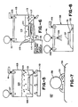
- the article 21 is placed in a pressure vessel chamber 23.
- De-ionized and filtered water or some other suitable cleaning liquid 25 is then introduced into the vessel 23 through a valve 27 until the article 21 is completely submerged in the liquid 25.
- the chamber 23 should not be completely filled with the cleaning liquid 25.
- a dissolving gas 29 is then bubbled through or otherwise introduced into the cleaning liquid 25 by opening a pressure valve 31 until a first desired gas pressure p1 is reached. A portion of the dissolving gas 29 thus introduced will be dissolved into the cleaning liquid 25, with the amount of gas thereby dissolved increasing with increasing gas overpressure in the pressure vessel chamber 23.
- the dissolving gas 29 is continually introduced into the chamber 23 until a sufficient amount of this gas is dissolved in the cleaning liquid 25 and equilibrium is established between the pressure of the gas dissolved in the cleaning liquid 25 and the gas pressure in the remainder of the pressure vessel chamber 23.
- a dissolving gas pressure of at least 150 psi is appropriate here.
- a pressure relief valve 33 on the pressure vessel is then suddenly opened.
- the dissolving gas pressure in the portion of the pressure vessel 23 that is not submerged in the cleaning liquid 23 drops quickly from the first pressure p1 to a second, much lower pressure p2, preferably in a time interval of the order of one second or less.
- the second gas pressure p2 may be approximately atmospheric pressure or may be some other pressure above or below atmospheric pressure.
- the remainder of the cleaning liquid may be drained from the pressure vessel by opening a drain 35 therein.
- the article 21 may be dried by directing dry nitrogen, helium, neon, argon, air or some other suitable dry gas at the surfaces of the article to remove all traces of the cleaning liquid 25 from such surfaces.
- a pressure vessel cover 37 may then be opened and the article 21 may be removed.
- Figs. 2 and 3 Two mechanisms of bubble formation and levitation are illustrated in Figs. 2 and 3.
- a single bubble 43 having a left lobe 43a and a right lobe 43b, is seen to form in the space between the contaminant particle 45 and the adjacent surface 47.
- the relatively high gas pressure within the bubble 43 having the shape shown in Fig. 2 then pushes the contaminant particle 45 away from the surface 47 in a reaction between the surface tension and internal pressure forces associated with the bunbble.
- the adhesion force that exists between this particle and this surface is decreased substantially, and the contaminant particle 45 becomes substantially free to rise to the top of the surrounding liquid 49, propelled by the buoyant force of the bubble 43.
- a bubble 51 first forms around a contaminant particle 53 that serves as a nucleus for such bubble. It is assumed here that the maximum diameter of the contaminant particle 53 is less than the equilibrium diameter of the bubble 51 that surrounds or encapsulates the contaminant particle. After the bubble 51 has formed around the contaminant particle 53, the buoyant force on the bubble/contaminant particle combination will cause this combination to move away from the adjacent designated surface 57. The adhesion force between contaminant particle 53 and surface 57 is reduced, allowing the combined bubble 51 and contaminant particle 53 to ascend toward an upper surface of the liquid 55.
- the article 61 to be cleaned is first placed in a pressure vessel 63, with the designated surface to be cleaned being exposed.
- the system is pressurized by opening a gas valve 65 until the pressure vessel is completely filled with a predetermined dissolving gas 66, such as dry nitrogen, helium, neon, argon or air at a first gas pressure p1.
- a predetermined dissolving gas 66 such as dry nitrogen, helium, neon, argon or air at a first gas pressure p1.
- de-ionized and filtered water or some other suitable cleaning liquid 67 is sprayed into the pressure vessel through an activatable spray nozzle at valve 69.
- numerous droplets of the cleaning liquid 67 are formed.
- An outlet valve 71 in the pressure vessel is suddenly opened and the gas pressure in the pressure vessel 63 is quickly reduced from the first gas pressure p1 to a second, lower gas pressure p2 that may be approximately atmospheric pressure.
- the sudden reduction in gas pressure within the pressure vessel 63 which preferably takes place in a time interval of the order of one second or less, causes spontaneous formation of bubbles of the dissolved gas 66 within the cleaning liquid 67. Many of these bubbles carry contaminant particles to the surface by one or the other of the mechanisms illustrated in Figs. 2 and 3.
- the contaminant particles are removed and the remaining cleaning liquid is drained by opening a liquid outlet valve 73 to drain the pressure vessel 63.
- the article 61 may then be dried by directing dry nitrogen, helium, neon, argon, air or other suitable, dry, relatively inert gas from a drying gas source 75 at the article to remove any remaining cleaning liquid from the surfaces of the article 61.
- a cover 77 on the pressure vessel 63 may then be removed and the article 61 may be removed for further processing.
- the article 101 to be cleaned is placed in a pressure vessel chamber 103 and the chamber is filled with a cleaning liquid 105 so that the article 101 is submerged in the liquid as before, with some chamber volume remaining that is not filled with the liquid.
- An inlet valve 107 in the chamber 103 is then opened, and the interior of the chamber 103 is pressurized with a dissolving gas 109 at some high pressure p1 of the order of 150 psi or greater. After equilibrium is established in the chamber 103, a substantial portion of the dissolving gas 109 is dissolved in the cleaning liquid (still indicated as 105).
- the cleaning liquid 105 is now heated to a predetermined temperature T1 that is much greater than T room .
- T1 may be chosen greater than the boiling temperature T boil for the cleaning liquid 105 at atmospheric pressure, but below T boil at the higher pressure p1.
- the high gas pressure present in the chamber 103 will ensure that substantially no boiling takes place and that the cleaning liquid 105 remains as a liquid.
- a pressure relief valve 111 is suddenly opened, and the pressure within the pressure vessel chamber 103 drops quickly to a second, lower, predetermined gas pressure p2 that may be atmospheric pressure or higher or lower.
- the sudden reduction in chamber pressure again causes bubbles to form spontaneously in the cleaning liquid 105, with increased vigor due to the elevated temperature of the cleaning liquid 105, and the contaminant particles on the surface of the article 101 are carried toward the upper surface of the cleaning liquid 105, thereby removing the contaminant particles from the surface of the article 101.
- the choice of elevated temperature T1 is arbitrary here, but it may be preferable to choose T1 less than T boil so that most or all of the cleaning liquid 105 remains as a liquid and is not boiled away when the gas pressure within the pressure vessel chamber 103 is dropped from p1 to p2.
- elevated temperature T1 may also be constrained by the need to choose a temperature that does not damage the article 101 or its surface, which is in contact with the cleaning liquid 105 at the elevated temperature.
- the embodiment of the invention illustrated in Figure 5 may also be used to remove contaminant particles from a liquid, where the need to avoid damage to the article at an elevated temperature is no longer a consideration.
- FIG. 6 Another embodiment of the invention, illustrated in Figure 6, utilizes a cleaning liquid at a reduced temperature T which is less than T freeze .
- the article 113 to be cleaned is placed in a pressure vessel chamber 115, and the chamber is partially filled with a cleaning liquid 117 so that the article is submerged, but the chamber volume is not completely filled with the cleaning liquid 117.
- An inlet valve 121 in the pressure vessel chamber 115 is then opened and the interior of the chamber is pressurized with a dissolving gas 119 to a predetermined gas pressure p1.
- the temperature of the cleaning liquid 117 is now lowered to a temperature T2 below its freezing temperature T freeze , and a thin layer 120 of the cleaning liquid 117 is frozen onto the exposed designated surface of the article 113 that is to be cleaned.
- the temperature of the cleaning liquid 117 can be reduced to a temperature T2 which is less than T freeze by any of several techniques. In one technique, cooling fluid from a cooling fluid source 116 is circulated through the article support 114 adjacent to the article.
- cooling gas from a cooling fluid source is introduced into the pressure vessel chamber 115, in the portion of the chamber volume that is not occupied by the cleaning liquid 117 or the article 113, and contact of this cooling gas with the cleaning liquid cools the cleaning liquid to a temperature T2 which is less than T freeze .
- a pressure relief valve 123 in the pressure vessel chamber 115 is suddenly opened, and the chamber gas pressure is quickly reduced from the value p1 to a lower value p2, which may be atmospheric pressure or higher or lower.
- This sudden reduction in chamber gas pressure may cause the frozen layer 120, which contains the dissolved gas 119 at a pressure p1 that is many times the normal atmospheric pressure, to undergo a phase change from its solid form, either to a liquid form or partly liquid form or to a gas form through sublimation.
- bubbles of the dissolved gas 119 spontaneously form in the layer 120 after the substance has undergone the phase change, and the bubbles thereby formed remove the contaminant particles from the designated surface of the article 113.
- Freezing of the cleaning liquid 117 with the bubbles therein may be advantageous for two reasons: (1) The freezing process further separates the contaminant particles from the surface of the article 113; and (2) When the frozen liquid recovers to its liquid state this occurs vigorously and this process helps propel the contaminant particles away from the surface.
- a very small amount of the cleaning liquid 131 which is assumed to have low or moderate surface tension, wets part or all of the designated surface of the article 133 to be cleaned; and the cleaning liquid 131 that is present is assumed to accumulate by capillary action or otherwise in the crevices formed between a contaminant particle 135 and the adjacent portion of the designated surface of the article 133.
- a dissolving gas 137 is now admitted to the chamber at a pressure p1 that is many times atmospheric pressure, and a portion of the dissolving gas becomes dissolved in the cleaning liquid (still indicated as 131) in the crevices.
- An outlet valve for the chamber is suddenly opened, the pressure of the dissolving gas quickly drops from p1 to a much lower value p2, and a phase change occurs in the cleaning liquid 131 in the crevices that propels the contaminant particle 135 away from the surface of the article 133 for removal from the chamber by other means.
- the cleaning liquid 131 should cover the designated surface of the article 133 to a depth of at most a small fraction of the characteristic diameter of one at the contaminant particles 135 to be removed.
- inventions illustrated in Figures 1, 4, 5, 6 and 7 are useful in cleaning planar surfaces or non-planar surfaces that have many peaks and valleys therein.
- One useful application of this invention is in removing contaminant particles from trenches or other vertical depressions formed in a semiconductor chip or wafer surface during processing of the chip.
- the invention will remove contaminant particles down to and below 0.1 ⁇ m and may thus be useful in cleaning trenches that have transverse widths of the order of 0.5-10 ⁇ m, or even lower.
- care should be taken to ensure that the cleaning liquid used thoroughly wets the surfaces of the trench so that any contaminant particles in the trench can be removed by the techniques disclosed in this application.
- Care should also be taken to remove the contaminant-bearing bubbles as these bubbles rise toward the upper surface of the liquid so that the contaminant particles do not sink back into the trenches if and when the bubbles burst.
- Figs. 1, 4, 5, 6 and 7 indicate that the entire article is submerged in the cleaning liquid
- the invention may also be practiced by providing only a thin layer of liquid on the surface to be cleaned, with the remainder of the article not being submerged in the cleaning liquid.
- One method of accomplishing this is illustrated in Fig. 8, where a wafer 131 is positioned on a pedestal 133 adjacent to one side of a chamber 135 that may be substantially evacuated.
- a layer 137 of the cleaning liquid may be deposited on an exposed surface of the article 131 by a spray 139 of such liquid directed at the article surface from a cleaning liquid source 141.
- the chamber 135 may also be provided with a gas source 143, positioned adjacent to the chamber to introduce therein a gas at high pressure, and a gas outlet valve 145 to quickly remove the gas from the chamber interior and thereby drop the chamber pressure rapidly. Provision of a laver 137 of cleaning liquid of thickness as small as ten ⁇ m on the surface of the article 131 to be cleaned should be sufficient to allow contaminant particles to be removed from the article surface by means of the liquid freeze and pressure drop processes discussed above.
- the present invention is not restricted to the use of water as the cleaning liquid or to the use of nitrogen, helium, neon, argon or air as the dissolved gas.
- Other cleaning liquids such as a mixture of water (85 percent or more by volume) with isopropyl alcohol, isobutyl alcohol or fluorocarbons, can be used for the cleaning liquid.
- Other gases can be used for the dissolving gas.
- a suitable dissolving gas should have appropriate solubility in the cleaning liquid, and the gas's physical and chemical properties should be compatible with the liquid and with the surface to be cleaned.
- the substance would be pressurized to form a liquid into which the surface to be cleaned is placed.
- the gas pressure in the pressure vessel would then be quickly reduced and a portion of the liquid would vaporize, forming bubbles around the contaminant particles and lifting the contaminant particles toward the upper surface of the remaining liquid. Particles are thereby removed.
Landscapes
- Cleaning Or Drying Semiconductors (AREA)
- Cleaning By Liquid Or Steam (AREA)
- Cleaning In General (AREA)
Applications Claiming Priority (2)
| Application Number | Priority Date | Filing Date | Title |
|---|---|---|---|
| US43509789A | 1989-11-13 | 1989-11-13 | |
| US435097 | 1989-11-13 |
Publications (2)
| Publication Number | Publication Date |
|---|---|
| EP0428983A2 true EP0428983A2 (de) | 1991-05-29 |
| EP0428983A3 EP0428983A3 (en) | 1991-12-11 |
Family
ID=23726969
Family Applications (1)
| Application Number | Title | Priority Date | Filing Date |
|---|---|---|---|
| EP19900121717 Withdrawn EP0428983A3 (en) | 1989-11-13 | 1990-11-13 | Particle removal from surfaces by pressure change |
Country Status (3)
| Country | Link |
|---|---|
| EP (1) | EP0428983A3 (de) |
| JP (1) | JPH03184337A (de) |
| KR (1) | KR910010639A (de) |
Cited By (17)
| Publication number | Priority date | Publication date | Assignee | Title |
|---|---|---|---|---|
| WO1995035580A1 (de) * | 1994-06-22 | 1995-12-28 | International Business Machines Corporation | Vorrichtung und verfahren zum ablösen von partikeln auf gegenständen |
| US5555902A (en) * | 1993-04-26 | 1996-09-17 | Sematech, Inc. | Submicron particle removal using liquid nitrogen |
| WO1998033208A1 (de) * | 1997-01-22 | 1998-07-30 | Fraunhofer-Gesellschaft zur Förderung der angewandten Forschung e.V. | Verfahren und vorrichtung zur reinigung von substratoberflächen |
| US5921257A (en) * | 1996-04-24 | 1999-07-13 | Steag Microtech Gmbh | Device for treating substrates in a fluid container |
| WO2000026947A1 (en) * | 1998-10-30 | 2000-05-11 | Fsi International, Inc. | Method and system to control the concentration of dissolved gas in a liquid |
| US6106634A (en) * | 1999-02-11 | 2000-08-22 | Applied Materials, Inc. | Methods and apparatus for reducing particle contamination during wafer transport |
| US6406551B1 (en) | 1999-05-14 | 2002-06-18 | Fsi International, Inc. | Method for treating a substrate with heat sensitive agents |
| US6488271B1 (en) | 1997-10-29 | 2002-12-03 | Fsi International, Inc. | Method to increase the quantity of dissolved gas in a liquid and to maintain the increased quantity of dissolved gas in the liquid until utilized |
| US6736150B2 (en) | 1999-07-06 | 2004-05-18 | Semitool, Inc. | Fluid heating system for processing semiconductor materials |
| WO2006013313A1 (en) * | 2004-08-03 | 2006-02-09 | Rolls-Royce Plc | Pressure treatment method |
| US7410545B2 (en) * | 2005-05-27 | 2008-08-12 | Dainippon Screen Mfg. Co., Ltd. | Substrate processing method of and substrate processing apparatus for freezing and cleaning substrate |
| WO2013102857A1 (en) * | 2012-01-02 | 2013-07-11 | Hyperflo Llc | Methods and systems for cleaning for cyclic nucleation transport (cnx) |
| WO2013158802A1 (en) | 2012-04-18 | 2013-10-24 | Advanced Wet Technogogies Gmbh | Dynamic chamber for cycle nucleation technology |
| WO2013169677A1 (en) * | 2012-05-06 | 2013-11-14 | Advanced Wet Technologies Gmbh | Hyperbaric methods and systems for surface treatment, cleaning, and drying |
| WO2014052508A1 (en) * | 2012-09-25 | 2014-04-03 | Advanced Wet Technogogies Gmbh | Gas expansion displacement cnx concept, methods and apparatus. |
| WO2014205143A1 (en) * | 2013-06-18 | 2014-12-24 | Advanced Wet Technologies Gmbh | Hyperbaric methods and systems for surface treatment, cleaning, and drying: thin liquid h-cnx |
| CN109570150A (zh) * | 2018-12-19 | 2019-04-05 | 江苏大学 | 一种激光诱导空泡双面清洗超薄零件的装置与方法 |
Families Citing this family (3)
| Publication number | Priority date | Publication date | Assignee | Title |
|---|---|---|---|---|
| US20060124155A1 (en) * | 2004-12-13 | 2006-06-15 | Suuronen David E | Technique for reducing backside particles |
| JP5643007B2 (ja) * | 2010-07-05 | 2014-12-17 | スリーエム イノベイティブ プロパティズ カンパニー | 表面構造体の乾燥方法 |
| JP6612015B2 (ja) * | 2013-03-28 | 2019-11-27 | 芝浦メカトロニクス株式会社 | 基板処理装置及び基板処理方法 |
Family Cites Families (2)
| Publication number | Priority date | Publication date | Assignee | Title |
|---|---|---|---|---|
| US4238244A (en) * | 1978-10-10 | 1980-12-09 | Halliburton Company | Method of removing deposits from surfaces with a gas agitated cleaning liquid |
| US4962776A (en) * | 1987-03-26 | 1990-10-16 | Regents Of The University Of Minnesota | Process for surface and fluid cleaning |
-
1990
- 1990-11-13 JP JP2306980A patent/JPH03184337A/ja active Pending
- 1990-11-13 EP EP19900121717 patent/EP0428983A3/en not_active Withdrawn
- 1990-11-13 KR KR1019900018318A patent/KR910010639A/ko not_active Withdrawn
Cited By (21)
| Publication number | Priority date | Publication date | Assignee | Title |
|---|---|---|---|---|
| US5555902A (en) * | 1993-04-26 | 1996-09-17 | Sematech, Inc. | Submicron particle removal using liquid nitrogen |
| DE4421843A1 (de) * | 1994-06-22 | 1996-01-04 | Ibm | Vorrichtung und Verfahren zum Ablösen von Partikeln auf Gegenständen |
| WO1995035580A1 (de) * | 1994-06-22 | 1995-12-28 | International Business Machines Corporation | Vorrichtung und verfahren zum ablösen von partikeln auf gegenständen |
| US5921257A (en) * | 1996-04-24 | 1999-07-13 | Steag Microtech Gmbh | Device for treating substrates in a fluid container |
| WO1998033208A1 (de) * | 1997-01-22 | 1998-07-30 | Fraunhofer-Gesellschaft zur Förderung der angewandten Forschung e.V. | Verfahren und vorrichtung zur reinigung von substratoberflächen |
| US6488271B1 (en) | 1997-10-29 | 2002-12-03 | Fsi International, Inc. | Method to increase the quantity of dissolved gas in a liquid and to maintain the increased quantity of dissolved gas in the liquid until utilized |
| US6648307B2 (en) | 1997-10-29 | 2003-11-18 | Fsi International, Inc. | Method to increase the quantity of dissolved gas in a liquid and to maintain the increased quantity of dissolved gas in the liquid until utilized |
| WO2000026947A1 (en) * | 1998-10-30 | 2000-05-11 | Fsi International, Inc. | Method and system to control the concentration of dissolved gas in a liquid |
| US6235641B1 (en) | 1998-10-30 | 2001-05-22 | Fsi International Inc. | Method and system to control the concentration of dissolved gas in a liquid |
| US6106634A (en) * | 1999-02-11 | 2000-08-22 | Applied Materials, Inc. | Methods and apparatus for reducing particle contamination during wafer transport |
| US6406551B1 (en) | 1999-05-14 | 2002-06-18 | Fsi International, Inc. | Method for treating a substrate with heat sensitive agents |
| US6736150B2 (en) | 1999-07-06 | 2004-05-18 | Semitool, Inc. | Fluid heating system for processing semiconductor materials |
| WO2006013313A1 (en) * | 2004-08-03 | 2006-02-09 | Rolls-Royce Plc | Pressure treatment method |
| US7410545B2 (en) * | 2005-05-27 | 2008-08-12 | Dainippon Screen Mfg. Co., Ltd. | Substrate processing method of and substrate processing apparatus for freezing and cleaning substrate |
| WO2013102857A1 (en) * | 2012-01-02 | 2013-07-11 | Hyperflo Llc | Methods and systems for cleaning for cyclic nucleation transport (cnx) |
| WO2013158802A1 (en) | 2012-04-18 | 2013-10-24 | Advanced Wet Technogogies Gmbh | Dynamic chamber for cycle nucleation technology |
| EP2838673A4 (de) * | 2012-04-18 | 2017-07-12 | LPW Reinigungssysteme GmbH | Dynamische kammer für eine keimbildungszyklus-technologie |
| WO2013169677A1 (en) * | 2012-05-06 | 2013-11-14 | Advanced Wet Technologies Gmbh | Hyperbaric methods and systems for surface treatment, cleaning, and drying |
| WO2014052508A1 (en) * | 2012-09-25 | 2014-04-03 | Advanced Wet Technogogies Gmbh | Gas expansion displacement cnx concept, methods and apparatus. |
| WO2014205143A1 (en) * | 2013-06-18 | 2014-12-24 | Advanced Wet Technologies Gmbh | Hyperbaric methods and systems for surface treatment, cleaning, and drying: thin liquid h-cnx |
| CN109570150A (zh) * | 2018-12-19 | 2019-04-05 | 江苏大学 | 一种激光诱导空泡双面清洗超薄零件的装置与方法 |
Also Published As
| Publication number | Publication date |
|---|---|
| KR910010639A (ko) | 1991-06-29 |
| JPH03184337A (ja) | 1991-08-12 |
| EP0428983A3 (en) | 1991-12-11 |
Similar Documents
| Publication | Publication Date | Title |
|---|---|---|
| EP0428983A2 (de) | Partikelentfernung von Oberflächen durch Druckwechsel | |
| US4962776A (en) | Process for surface and fluid cleaning | |
| US4817652A (en) | System for surface and fluid cleaning | |
| KR100397455B1 (ko) | 반도체의초미립자세정기 | |
| JP3183214B2 (ja) | 洗浄方法および洗浄装置 | |
| EP1039506B1 (de) | Vorrichtung zur Reinigung und Trocknung von Substraten | |
| KR101122377B1 (ko) | 압축/가압 폼, 기포 및 액체를 이용하여 반도체 웨이퍼를세정하는 방법 및 장치 | |
| US5698038A (en) | Method for wafer carrier cleaning | |
| US5723019A (en) | Drip chemical delivery method and apparatus | |
| US20030075204A1 (en) | Methods for wafer proximity cleaning and drying | |
| KR20040075323A (ko) | 단일- 또는 두-기판 처리용 장치 및 방법 | |
| JPH03145130A (ja) | 物体表面から汚染粒子を除去する装置及び方法 | |
| JPH06103678B2 (ja) | 半導体基板の加工方法 | |
| US20010013355A1 (en) | Fast single-article megasonic cleaning process for single-sided or dual-sided cleaning | |
| US5958146A (en) | Ultra-low particle semiconductor cleaner using heated fluids | |
| US6502591B1 (en) | Surface tension effect dryer with porous vessel walls | |
| JPH07159980A (ja) | 基板洗浄装置 | |
| US20040016442A1 (en) | Megasonically energized liquid interface apparatus and method | |
| EP1726035A1 (de) | Vorrichtung und verfahren zum trocknen von substraten | |
| JP2003503830A (ja) | 化学的膜洗浄及び乾燥 | |
| KR20100060094A (ko) | 기판 이면 세정 방법 | |
| JP3289035B2 (ja) | 半導体ウエハの洗浄方法 | |
| JPH03190131A (ja) | 半導体基板の洗浄装置 | |
| CN114536213B (zh) | 清洁抛光垫的设备和抛光装置 | |
| JP2767165B2 (ja) | ウエーハ洗浄槽 |
Legal Events
| Date | Code | Title | Description |
|---|---|---|---|
| PUAI | Public reference made under article 153(3) epc to a published international application that has entered the european phase |
Free format text: ORIGINAL CODE: 0009012 |
|
| AK | Designated contracting states |
Kind code of ref document: A2 Designated state(s): BE CH DE ES FR GB IT LI NL |
|
| PUAL | Search report despatched |
Free format text: ORIGINAL CODE: 0009013 |
|
| AK | Designated contracting states |
Kind code of ref document: A3 Designated state(s): BE CH DE ES FR GB IT LI NL |
|
| 17P | Request for examination filed |
Effective date: 19920224 |
|
| 17Q | First examination report despatched |
Effective date: 19930510 |
|
| STAA | Information on the status of an ep patent application or granted ep patent |
Free format text: STATUS: THE APPLICATION IS DEEMED TO BE WITHDRAWN |
|
| 18D | Application deemed to be withdrawn |
Effective date: 19930921 |