EP0428962A2 - Wall footing for an upright profile - Google Patents
Wall footing for an upright profile Download PDFInfo
- Publication number
- EP0428962A2 EP0428962A2 EP90121555A EP90121555A EP0428962A2 EP 0428962 A2 EP0428962 A2 EP 0428962A2 EP 90121555 A EP90121555 A EP 90121555A EP 90121555 A EP90121555 A EP 90121555A EP 0428962 A2 EP0428962 A2 EP 0428962A2
- Authority
- EP
- European Patent Office
- Prior art keywords
- facade
- base plate
- receiving shoe
- base
- fastening screw
- Prior art date
- Legal status (The legal status is an assumption and is not a legal conclusion. Google has not performed a legal analysis and makes no representation as to the accuracy of the status listed.)
- Granted
Links
Images

Classifications
-
- E—FIXED CONSTRUCTIONS
- E04—BUILDING
- E04B—GENERAL BUILDING CONSTRUCTIONS; WALLS, e.g. PARTITIONS; ROOFS; FLOORS; CEILINGS; INSULATION OR OTHER PROTECTION OF BUILDINGS
- E04B2/00—Walls, e.g. partitions, for buildings; Wall construction with regard to insulation; Connections specially adapted to walls
- E04B2/88—Curtain walls
- E04B2/96—Curtain walls comprising panels attached to the structure through mullions or transoms
Definitions
- the invention relates to a facade base for a post profile, which forms the framework of a building facade with other post and rung profiles.
- the invention has for its object to design a facade base for a post profile so that it is adjustable in three dimensions in a wide range.
- a facade foot which has a base plate and a height-adjustable receptacle between the vertical guide tracks of the base plate for the lower end of the post profile and in each case a through hole provided in the base plate between an end face and a guide track for a fastening screw with a substantially has a larger diameter than the diameter of the fastening screw and at least one adjustment plate assigned to the push-through hole, through which the shaft of the fastening screw is guided and on which the head of the fastening screw is supported.
- the post profile defined in the receiving shoe can be aligned in the vertical direction by means of an adjusting screw.
- the base plate is also designed so that it is adjustable in relation to its fastening screws in its longitudinal direction and in a direction transverse to it.
- the facade base according to the invention is structurally simple, so that the assembly, the fixing of the post profile in the receiving shoe and the adjustment in the dimensions mentioned can be carried out without difficulty.
- the post profile which is generally designed as a hollow chamber profile, has anchoring grooves on the outside for sealing professionals and a fastening groove, e.g. a screw groove for cover profiles. Between these anchoring or fastening grooves, grooves or grooves are arranged for draining off the leachate.
- the post profile is arranged and fixed in the receiving shoe or in the facade base so that the parts carrying the leachate are outside the facade base and the leachate e.g. can be derived from the respective post profile from the area of the facade base by means of a film.
- the facade base 1 has a base plate 2 with vertical guideways 3 and a receiving shoe 4.
- This receiving shoe 4 for the lower end 5 of a post profile 6 is U-shaped in vertical section and is equipped with side cheeks 7 which carry guide pieces 8 on the outside.
- these guide pieces are formed in one piece with the side cheeks and engage in the guide tracks 3, which are delimited by vertical webs 9, which are integral with the base plate 2.
- a set screw 13 is used, which is supported with its head 14 on the base plate 2 and extends with its shaft through a hole in the base 10 and in a bar 15 integral with the base and into the Interior of the receiving shoe protrudes.
- the threaded shaft of the adjusting screw is equipped with a lock nut 16, through which the upper stroke end of the receiving shoe is determined in cooperation with a spacer tube 17, which surrounds the threaded shaft and is supported on the base 10.
- the post profile 6 is fixed by two bolts 18 which extend parallel to one another, the bolts being guided through the side cheeks 7 of the receiving shoe.
- the bolts can be designed as threaded bolts or as thread-free bolts.
- FIGS. 2 and 3 thread-free bolts 18 show a head 19 on one side and a pin on the other side.
- the height adjustment of the receiving shoe 4 takes place by means of a nut 20 on which the base 10 or the last 15 is supported.
- the post profile has a screw groove 21 in the center for fixing cover profiles and anchoring grooves 22 for sealing strips adjacent to the longitudinal edges. Between the central screw groove and an anchoring groove for a sealing strip there is a channel 23 for leachate in the post profile, this channel being delimited by a bottom 24.
- this floor is offset from the outer boundary surface 25 of the facade base to the outside, so that at the lower end of the post profile, a film 24 engaging behind the floor can be provided, through which the leachate can be drained.
- an adjustment plate 27 and a base plate 28 are provided for adjusting the facade base in the direction of the longitudinal axis 26 and in the transverse direction. Furthermore, a bore 30 is arranged in the area of the base plate between a front end 29 and the guideway 3, the diameter of which is a multiple of the diameter of the fastening screw 31.
- the base plate 28 extends in the direction of the longitudinal axis 26 of the facade foot over the area of the base plate 2 between a face bar 32 and the webs 9 delimiting the guideways.
- the base plate has edge strips 33 which extend in the longitudinal direction and surround the longitudinal edges of the base plate 2, so that the reason plate 28 is positively fixed on the base plate 2.
- the base plate 28 is also provided with a bore 34a which is aligned with the bore 30 in the base plate 2.
- the upper boundary surface of the base plate has corrugations or serrations 34b extending in the longitudinal direction of the facade base, into which corrugations or serrations 35 provided on the underside of the adjustment plate 27 engage.
- the adjustment plate has a cylindrical socket 36 on the underside for pushing through the shaft of the fastening screw 31.
- This nozzle engages in the bores 34a and.
- the facade base can be moved in the direction of the longitudinal axis 26. It is also possible to disengage the corrugations 34b and 35, i.e. raise the adjustment plate 27 and make an adjustment transversely to the longitudinal axis 26.
- the upper boundary surface of the base plate 2 with a corrugation or toothing extending in the longitudinal direction of the base plate in an area adjacent to the through hole 30 and to place the adjustment plate 21 on this profiled surface.
Landscapes
- Engineering & Computer Science (AREA)
- Architecture (AREA)
- Physics & Mathematics (AREA)
- Electromagnetism (AREA)
- Civil Engineering (AREA)
- Structural Engineering (AREA)
- Finishing Walls (AREA)
- Orthopedics, Nursing, And Contraception (AREA)
- Ladders (AREA)
- Rod-Shaped Construction Members (AREA)
- Steps, Ramps, And Handrails (AREA)
- Floor Finish (AREA)
- Buildings Adapted To Withstand Abnormal External Influences (AREA)
- Load-Bearing And Curtain Walls (AREA)
Abstract
Description
Die Erfindung bezieht sich auf einen Fassadenfuß für ein Pfostenprofil, das mit weiteren Pfosten- und Sprossenprofilen das Rahmenwerk einer Gebäudefassade bildet.The invention relates to a facade base for a post profile, which forms the framework of a building facade with other post and rung profiles.
Bei der Erstellung der Fassade ist es wichtig, daß die Pfostenprofile mit einfachen Mitteln zueinander ausgerichtet werden können.When creating the facade, it is important that the post profiles can be aligned with each other using simple means.
Der Erfindung liegt die Aufgabe zugrunde, einen Fassadenfuß für ein Pfostenprofil so zu gestalten, daß er in drei Dimensionen in einem weiten Bereich verstellbar ist.The invention has for its object to design a facade base for a post profile so that it is adjustable in three dimensions in a wide range.
Diese Aufgabe wird nach der Erfindung durch einen Fassadenfuß gelöst, der eine Bodenplatte und einen zwischen vertikalen Führungsbahnen der Bodenplatte höhenverstellbar angeordneten Aufnahmeschuh für das untere Ende des Pfostenprofils und jeweils eine in der Bodenplatte zwischen einer Stirnseite und einer Führungsbahn vorgesehene Durchsteckbohrung für eine Befestigungsschraube mit einem wesentlich größeren Durchmesser als der Durchmesser der Befestigungsschraube und mindestens eine der Durchsteckbohrung zugeordnete Verstellplatte aufweist, durch die der Schaft der Befestigungsschraube geführt ist und an der sich der Kopf der Befestigungsschraube abstützt.This object is achieved according to the invention by a facade foot, which has a base plate and a height-adjustable receptacle between the vertical guide tracks of the base plate for the lower end of the post profile and in each case a through hole provided in the base plate between an end face and a guide track for a fastening screw with a substantially has a larger diameter than the diameter of the fastening screw and at least one adjustment plate assigned to the push-through hole, through which the shaft of the fastening screw is guided and on which the head of the fastening screw is supported.
Das in dem Aufnahmeschuh festgelegte Pfostenprofil kann mittels einer Stellschraube in vertikaler Richtung ausgerichtet werden.The post profile defined in the receiving shoe can be aligned in the vertical direction by means of an adjusting screw.
Die Bodenplatte ist ferner so gestaltet, daß sie gegenüber ihren Befestigungsschrauben in ihrer Längsrichtung und in einer quer dazu laufenden Richtung verstellbar ist.The base plate is also designed so that it is adjustable in relation to its fastening screws in its longitudinal direction and in a direction transverse to it.
Der erfindungsgemäße Fassadenfuß ist konstruktiv einfach aufgebaut, so daß die Montage, die Festlegung des Pfostenprofils im Aufnahmeschuh und die Verstellung in den genannten Dimensionen ohne Schwierigkeiten durchführbar sind.The facade base according to the invention is structurally simple, so that the assembly, the fixing of the post profile in the receiving shoe and the adjustment in the dimensions mentioned can be carried out without difficulty.
Das Pfostenprofil, das im allgemeinen als Hohlkammerprofil ausgeführt wird, weist an der Stirnaußenseite Verankerungsnuten für Dichtungsprofiie sowie eine Befestigungssnut, z.B. eine Schraubnut für Abdeckprofile auf. Zwischen diesen Verankerungs- bzw. Befestigungsnuten sind Rinnen oder Nuten zum Abführen des Sickerwassers angeordnet.The post profile, which is generally designed as a hollow chamber profile, has anchoring grooves on the outside for sealing professionals and a fastening groove, e.g. a screw groove for cover profiles. Between these anchoring or fastening grooves, grooves or grooves are arranged for draining off the leachate.
Das Pfostenprofil wird im Aufnahmeschuh bzw. im Fassadenfuß so angeordnet und festgelegt, daß die das Sickerwasser führenden Teile außerhalb des Fassadenfußes liegen und das Sickerwasser z.B. mittels einer Folie von dem jeweiligen Pfostenprofil aus dem Bereich des Fassadenfußes abgeleitet werden kann.The post profile is arranged and fixed in the receiving shoe or in the facade base so that the parts carrying the leachate are outside the facade base and the leachate e.g. can be derived from the respective post profile from the area of the facade base by means of a film.
Weitere Merkmale der Erfindung ergeben sich aus den Unteransprüchen. Ein Ausführungsbeispiel des erfindungsgemäßen Fassadenfußes ist in den Zeichnungen dargestellt und wird im folgenden beschrieben. Es zeigen:
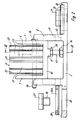
- Fig. 1 den Fassadenfuß in perspektivischer Darstellung,
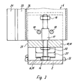
- Fig. 2 den Fassadenfuß mit eingesetztem Pfostenprofil im Aufriß und auf der linken Seite teilweise demontiert und geschnitten, sowie
- Fig. 3 einen Schnitt nach der Linie III-III in Fig. 2.
- 1 is a perspective view of the facade base,
- Fig. 2, the facade base with inserted post profile in elevation and on the left side partially disassembled and cut, and
- 3 shows a section along the line III-III in FIG. 2nd
Der Fassadenfuß 1 weist eine Bodenplatte 2 mit vertikalen Führungsbahnen 3 und einen Aufnahmeschuh 4 auf. Dieser Aufnahmeschuh 4 für das untere Ende 5 eines Pfostenprofils 6 ist im Vertikalschnitt U-förmig ausgebildet und ist mit Seitenwangen 7 ausgestattet, die an der Außenseite Führungsstücke 8 tragen. Diese Führungsstücke sind in dem dargestellten Ausführungsbeispiel einstückig mit den Seitenwangen ausgebildet und greifen in die Führungsbahnen 3 ein, die durch vertikale Stege 9 begrenzt werden, die mit der Bodenplatte 2 einstückig sind.The facade base 1 has a
Insbesondere aus der Fig. 2 ergibt sich, daß die Führungsstücke 8 den Boden 10 des Aufnahmeschuhs nach unten überragen. Hierdurch wird erreicht, daß die untere Begrenzungsfläche 11 sich in der unteren Endstellung des Aufnahmeschuhs an eine Anschlagfläche 12 der Bodenplatte 2 legt. Durch die erwähnte Gestaltung der Führungsstücke 8 wird somit durch diese Führungsstücke die untere Endstellung des Aufnahmeschuhs bestimmt.2 that the
Zur Höhenverstellung des Aufnahmeschuhs 4 gegenüber der Bodenplatte 2 wird eine Stellschraube 13 verwendet, die sich mit ihrem Kopf 14 an der Grundplatte 2 abstützt und sich mit ihrem Schaft durch eine Bohrung im Boden 10 und in einer mit dem Boden einstückigen Leiste 15 erstreckt und in den Innenraum des Aufnahmeschuhs ragt. Am freien Ende ist der Gewindeschaft der Stellschraube mit einer Kontermutter 16 ausgerüstet, durch die im Zusammenwirken mit einem Distanzrohr 17, das den Gewindeschaft umschließt und sich am Boden 10 abstützt, das obere Hubende des Aufnahmeschuhs bestimmt wird.For adjusting the height of the receiving shoe 4 relative to the
Im Aufnahmeschuh wird das Pfostenprofil 6 durch zwei parallel zueinander sich erstreckende Bolzen 18 festgelegt, wobei die Bolzen durch die Seitenwangen 7 des Aufnahmeschuhs geführt werden. Die Bolzen können als Gewindebolzen oder als gewindefreie Bolzen ausgeführt werden.In the receiving shoe, the post profile 6 is fixed by two
Beim Ausführungsbeispiel nach der Fig. 1 sind als Schrauben ausgebildete Gewindebolzen vorgesehen, während die Fig. 2 und 3 gewindefreie Bolzen 18 zeigen, die auf der einen Seite einen Kopf 19 aufweisen und auf der anderen Seite durch einen Splint festgelegt werden.In the embodiment according to FIG. 1, threaded bolts designed as screws are provided, while FIGS. 2 and 3 thread-
Die Höhenverstellung des Aufnahmeschuhs 4 erfolgt mittels einer Mutter 20, auf der sich der Boden 10 bzw. die Leiste 15 abstützt.The height adjustment of the receiving shoe 4 takes place by means of a
Aus der Fig. 3 ergibt sich, daß das Pfostenprofil aus dem Aufnahmeschuh 4 an der Vorderseite herausragt.From Fig. 3 it follows that the post profile protrudes from the receiving shoe 4 on the front.
An der vorderen Stirnseite weist das Pfostenprofil mittig eine Schraubnut 21 zum Festlegen von Abdeckprofilen und benachbart den Längsrändern Verankerungsnuten 22 für Dichtungsleisten auf. Zwischen der mittigen Schraubnut und einer Verankerungsnut für eine Dichtungsleiste ist bei dem Pfostenprofil jeweils eine Rinne 23 für Sickerwasser vorhanden, wobei diese Rinne durch einen Boden 24 begrenzt wird.At the front end, the post profile has a
Aus der Fig. 3 ergibt sich, daß dieser Boden gegenüber der äußeren Begrenzungsfläche 25 des Fassadenfußes nach außen versetzt ist, so daß am unteren Ende des Pfostenprofils eine den Boden 24 hintergreifende Folie vorgesehen werden kann, über die das Sickerwasser abgeführt werden kann.From Fig. 3 it follows that this floor is offset from the
Zur Verstellung des Fassadenfußes in Richtung der Längsachse 26 und in Querrichtung dazu sind in dem Ausführungsbeispiel eine Verstellplatte 27 und eine Grundplatte 28 vorgesehen. Ferner ist in dem Bereich der Bodenplatte zwischen einem Stirnende 29 und der Führungsbahn 3 eine Bohrung 30 angeordnet, deren Durchmesser ein Mehrfaches des Durchmessers der Befestigungsschraube 31 ist.In the exemplary embodiment, an
Die Grundplatte 28 erstreckt sich in Richtung der Längsachse 26 des Fassadenfußes über den Bereich der Bodenplatte 2 zwischen einer Stirnleiste 32 und den die Führungsbahnen begrenzenden Stegen 9. Die Grundplatte weist in Längsrichtung sich erstreckende Randleisten 33 auf, die die Längsränder der Bodenplatte 2 umgreifen, so daß die Grund platte 28 auf der Bodenplatte 2 formschlüssig festgelegt ist. Die Grundplatte 28 ist ferner mit einer Bohrung 34a versehen, die mit der Bohrung 30 in der Bodenplatte 2 fluchtet.The
Die obere Begrenzungsfläche der Grundplatte weist in Längsrichtung des Fassadenfußes sich erstreckende Riffelungen oder Verzahnungen 34b auf, in die an der Unterseite der Verstellplatte 27 vorgesehene Riffelungen oder Verzahnungen 35 eingreifen.The upper boundary surface of the base plate has corrugations or
Aus der Fig. 2 folgt, daß die Verstellplatte an der Unterseite einen zylindrischen Stutzen 36 zum Durchstecken des Schaftes der Befestigungsschraube 31 aufweist. Dieser Stutzen greift in die Bohrungen 34a und ein. Bei gelösten Befestigungsschrauben 31 kann der Fassadenfuß in Richtung der Längsachse 26 verschoben werden. Ferner besteht die Möglichkeit, die Riffelungen 34b und 35 außer Eingriff zu bringen, d.h. die Verstellplatte 27 anzuheben und eine Verstellung quer zur Längsachse 26 vorzunehmen.From Fig. 2 it follows that the adjustment plate has a
In Abwandlung der in den Zeichnungen dargestellten Ausführung ist es auch möglich, die obere Begrenzungsfläche der Bodenplatte 2 in einem an die Durchsteckbohrung 30 angrenzenden Bereich mit einer in Längsrichtung der Bodenplatte sich erstreckenden Riffelung oder Verzahnung zu versehen und auf diese profilierte Fläche die Verstellplatte 21 aufzusetzen.In a modification of the embodiment shown in the drawings, it is also possible to provide the upper boundary surface of the
- 1 Fassadenfuß1 facade base
- 2 Bodenplatte2 base plate
- 3 Führungsbahn3 guideway
- 4 Aufnahmeschuh4 recording shoes
- 5 unteres Ende5 bottom end
- 6 Pfostenprofil6 post profile
- 7 Seitenwange7 sidewalls
- 8 Führungsstück8 guide piece
- 9 Steg9 bridge
- 10 Boden10 floor
- 11 Begrenzungsfläche11 boundary surface
- 12 Anschlagfläche12 stop surface
- 13 Stellschraube13 set screw
- 14 Kopf14 head
- 15 Leiste15 bar
- 16 Kontermutter16 lock nut
- 17 Distanzrohr17 spacer tube
- 18 Bolzen18 bolts
- 19 Kopf19 head
- 20 Mutter20 mother
- 21 Schraubnut21 screw groove
- 22 Verankerungsnut22 anchoring groove
- 23 Rinne23 gutter
- 24 Boden24 floor
- 25 Begrenzungsfläche25 boundary surface
- 26 Längsachse26 longitudinal axis
- 27 Verstellplatte27 adjustment plate
- 28 Grundplatte28 base plate
- 29 Stirnende29 forehead
- 30 Bohrung30 hole
- 31 Befestigungsschraube31 fastening screw
- 32 Stirnleiste32 front molding
- 33 Randleiste33 sidebar
- 34a Bohrung34a bore
- 34b Riffelung34b corrugation
- 35 Verzahnung35 gearing
- 36 Stutzen36 sockets
Claims (11)
Priority Applications (1)
| Application Number | Priority Date | Filing Date | Title |
|---|---|---|---|
| AT90121555T ATE91314T1 (en) | 1989-11-24 | 1990-11-10 | FAÇADE BASE FOR A POST PROFILE. |
Applications Claiming Priority (2)
| Application Number | Priority Date | Filing Date | Title |
|---|---|---|---|
| DE3938871A DE3938871A1 (en) | 1989-11-24 | 1989-11-24 | FAÇADE FOOT FOR A POST PROFILE |
| DE3938871 | 1989-11-24 |
Publications (3)
| Publication Number | Publication Date |
|---|---|
| EP0428962A2 true EP0428962A2 (en) | 1991-05-29 |
| EP0428962A3 EP0428962A3 (en) | 1992-03-25 |
| EP0428962B1 EP0428962B1 (en) | 1993-07-07 |
Family
ID=6394080
Family Applications (1)
| Application Number | Title | Priority Date | Filing Date |
|---|---|---|---|
| EP90121555A Expired - Lifetime EP0428962B1 (en) | 1989-11-24 | 1990-11-10 | Wall footing for an upright profile |
Country Status (8)
| Country | Link |
|---|---|
| EP (1) | EP0428962B1 (en) |
| AT (1) | ATE91314T1 (en) |
| DE (2) | DE3938871A1 (en) |
| DK (1) | DK0428962T3 (en) |
| ES (1) | ES2043218T3 (en) |
| FI (1) | FI92948C (en) |
| NO (1) | NO177760C (en) |
| PT (1) | PT95979B (en) |
Cited By (7)
| Publication number | Priority date | Publication date | Assignee | Title |
|---|---|---|---|---|
| FR2694952A1 (en) * | 1992-08-18 | 1994-02-25 | Aluvar Sa | System for fixing a curtain wall stiffener on a building element. |
| NL1028915C2 (en) * | 2005-04-29 | 2006-10-31 | Hendriks Aluminium Geveltechni | Anchor for facade profile, comprises ribbed anchor plate for securing to profile and ribbed clamping plate |
| AT504064B1 (en) * | 2006-08-10 | 2008-05-15 | Mwt Micro Wood Technology Gmbh | PADDING DEVICE FOR A COMPLETED COMPONENT |
| WO2014076526A1 (en) * | 2012-11-19 | 2014-05-22 | Universita' Deglii Studi Di Padova | Wall base structure for light buildings |
| CN111236506A (en) * | 2020-01-20 | 2020-06-05 | 福建省兴岩建设集团有限公司 | Hang curtain futilely with short cantilever dry-hanging device |
| WO2021109373A1 (en) * | 2019-12-05 | 2021-06-10 | 上海江河幕墙系统工程有限公司 | Three-dimensionally adjustable curtain wall support |
| DE102020132669A1 (en) | 2020-12-08 | 2022-06-09 | Raico Bautechnik Gmbh | Fastening device and method for aligning and fixing a mullion profile of a mullion and transom construction |
Families Citing this family (5)
| Publication number | Priority date | Publication date | Assignee | Title |
|---|---|---|---|---|
| DE10236552B4 (en) * | 2002-08-08 | 2004-07-22 | Hilti Ag | Connection element for a mounting system |
| CN105350691A (en) * | 2015-12-01 | 2016-02-24 | 深圳市三鑫幕墙工程有限公司 | Curtain wall side hanging device |
| CN105350692A (en) * | 2015-12-01 | 2016-02-24 | 深圳市三鑫幕墙工程有限公司 | Unit-typed curtain wall multi-angle side-hanging device |
| CN109469234B (en) * | 2018-11-15 | 2020-04-03 | 北京江河幕墙系统工程有限公司 | Top and bottom connecting system of sitting type full-glass curtain wall and mounting method thereof |
| DE102019133978A1 (en) * | 2019-12-11 | 2021-06-17 | Mepa - Pauli Und Menden Gmbh | FASTENING ARRANGEMENT FOR FASTENING A FRAMEWORK FRAME OF A SANITARY INSTALLATION |
Citations (2)
| Publication number | Priority date | Publication date | Assignee | Title |
|---|---|---|---|---|
| US2914145A (en) * | 1955-01-26 | 1959-11-24 | Benson Russell Richard | Curtain wall framing |
| DE2639552A1 (en) * | 1976-09-02 | 1978-03-16 | Walter Haase | Grooved plate rear ventilated wall cladding panel holder - has wedge block, trapezoidal interlocking serration and vertical base grooves |
-
1989
- 1989-11-24 DE DE3938871A patent/DE3938871A1/en not_active Withdrawn
-
1990
- 1990-11-10 AT AT90121555T patent/ATE91314T1/en not_active IP Right Cessation
- 1990-11-10 EP EP90121555A patent/EP0428962B1/en not_active Expired - Lifetime
- 1990-11-10 ES ES90121555T patent/ES2043218T3/en not_active Expired - Lifetime
- 1990-11-10 DE DE9090121555T patent/DE59001914D1/en not_active Expired - Fee Related
- 1990-11-10 DK DK90121555.8T patent/DK0428962T3/en active
- 1990-11-23 PT PT95979A patent/PT95979B/en not_active IP Right Cessation
- 1990-11-23 FI FI905794A patent/FI92948C/en not_active IP Right Cessation
- 1990-11-23 NO NO905082A patent/NO177760C/en unknown
Patent Citations (2)
| Publication number | Priority date | Publication date | Assignee | Title |
|---|---|---|---|---|
| US2914145A (en) * | 1955-01-26 | 1959-11-24 | Benson Russell Richard | Curtain wall framing |
| DE2639552A1 (en) * | 1976-09-02 | 1978-03-16 | Walter Haase | Grooved plate rear ventilated wall cladding panel holder - has wedge block, trapezoidal interlocking serration and vertical base grooves |
Non-Patent Citations (1)
| Title |
|---|
| FRICK/KN\LL/NEUMANN: "BAUKONSTRUKTIONSLEHRE" 26. Auflage, Teil 1, 1975, Seite 147, B.G. Teubner, Stuttgart, DE * |
Cited By (11)
| Publication number | Priority date | Publication date | Assignee | Title |
|---|---|---|---|---|
| FR2694952A1 (en) * | 1992-08-18 | 1994-02-25 | Aluvar Sa | System for fixing a curtain wall stiffener on a building element. |
| EP0586320A1 (en) * | 1992-08-18 | 1994-03-09 | Alain Costa | System for the connection of a stiffening element of a curtain wall to a construction element |
| NL1028915C2 (en) * | 2005-04-29 | 2006-10-31 | Hendriks Aluminium Geveltechni | Anchor for facade profile, comprises ribbed anchor plate for securing to profile and ribbed clamping plate |
| AT504064B1 (en) * | 2006-08-10 | 2008-05-15 | Mwt Micro Wood Technology Gmbh | PADDING DEVICE FOR A COMPLETED COMPONENT |
| WO2014076526A1 (en) * | 2012-11-19 | 2014-05-22 | Universita' Deglii Studi Di Padova | Wall base structure for light buildings |
| US9556610B2 (en) | 2012-11-19 | 2017-01-31 | Universita' Degli Studi Di Padova | Wall base structure for light buildings |
| CN104968868B (en) * | 2012-11-19 | 2017-05-10 | 帕多瓦大学 | Wall base structure for light buildings |
| WO2021109373A1 (en) * | 2019-12-05 | 2021-06-10 | 上海江河幕墙系统工程有限公司 | Three-dimensionally adjustable curtain wall support |
| CN111236506A (en) * | 2020-01-20 | 2020-06-05 | 福建省兴岩建设集团有限公司 | Hang curtain futilely with short cantilever dry-hanging device |
| DE102020132669A1 (en) | 2020-12-08 | 2022-06-09 | Raico Bautechnik Gmbh | Fastening device and method for aligning and fixing a mullion profile of a mullion and transom construction |
| EP4012131A1 (en) | 2020-12-08 | 2022-06-15 | Raico Bautechnik GmbH | Fastening device and method for aligning and fixing a post profile of a post-bolt construction |
Also Published As
| Publication number | Publication date |
|---|---|
| NO177760C (en) | 1995-11-15 |
| PT95979B (en) | 1998-07-31 |
| ATE91314T1 (en) | 1993-07-15 |
| FI905794A0 (en) | 1990-11-23 |
| DE59001914D1 (en) | 1993-08-12 |
| FI92948B (en) | 1994-10-14 |
| ES2043218T3 (en) | 1993-12-16 |
| NO177760B (en) | 1995-08-07 |
| DE3938871A1 (en) | 1991-05-29 |
| PT95979A (en) | 1992-08-31 |
| EP0428962A3 (en) | 1992-03-25 |
| NO905082L (en) | 1991-05-27 |
| NO905082D0 (en) | 1990-11-23 |
| FI905794A (en) | 1991-05-25 |
| DK0428962T3 (en) | 1993-12-13 |
| FI92948C (en) | 1995-01-25 |
| EP0428962B1 (en) | 1993-07-07 |
Similar Documents
| Publication | Publication Date | Title |
|---|---|---|
| DE3343066A1 (en) | FURNITURE WITH HEIGHT AND / OR INCLINATION TABLE TOP | |
| EP0428962B1 (en) | Wall footing for an upright profile | |
| EP0729003A2 (en) | Edge seal for heat exchange plate | |
| DE202015106963U1 (en) | Glass railing support structure and wedge profile part for use in such an arrangement | |
| EP0392341B1 (en) | Metal or wooden glazed window | |
| EP0687784B1 (en) | Drainage gully for buildings | |
| DE3529877C1 (en) | Apparatus for bridging expansion joints | |
| DE19511206C2 (en) | Building drainage channel | |
| DE4210575A1 (en) | Framework design for glass roofs and glass facades - where cross beams are connected by sliding bolt sections to main beams. | |
| DE10150707C5 (en) | Device for receiving a running element | |
| EP0682188A2 (en) | Linear bearing assembly | |
| DE10150709A1 (en) | Awning especially for conservatories has winding shaft set in box having in each guide rail area a retaining foot which can engage with clamping device | |
| DE4332437A1 (en) | Table and table system | |
| EP1428948A1 (en) | Drainage channel | |
| DE4424916C2 (en) | Composite profile | |
| EP0383213B1 (en) | Console support | |
| EP0877125B1 (en) | Mounting frame for sanitary appliances | |
| DE19912143B4 (en) | Component set for the construction of a greenhouse | |
| EP0799945A1 (en) | Construction of mullions and transoms | |
| DE3510759A1 (en) | Height-adjustment device for vehicle roof covers which can at least be knocked out | |
| DE3426461C1 (en) | Sealing device | |
| DE3611827A1 (en) | Holding device for a panel of a shop counter | |
| DE2810981C2 (en) | Device for fastening a frame | |
| DE4321415C2 (en) | Device and method for changing the height position of a roof structure | |
| EP0172575A2 (en) | Connecting arrangement |
Legal Events
| Date | Code | Title | Description |
|---|---|---|---|
| PUAI | Public reference made under article 153(3) epc to a published international application that has entered the european phase |
Free format text: ORIGINAL CODE: 0009012 |
|
| AK | Designated contracting states |
Kind code of ref document: A2 Designated state(s): AT BE CH DE DK ES FR GB IT LI LU NL SE |
|
| PUAL | Search report despatched |
Free format text: ORIGINAL CODE: 0009013 |
|
| AK | Designated contracting states |
Kind code of ref document: A3 Designated state(s): AT BE CH DE DK ES FR GB IT LI LU NL SE |
|
| 17P | Request for examination filed |
Effective date: 19920221 |
|
| 17Q | First examination report despatched |
Effective date: 19920917 |
|
| ITF | It: translation for a ep patent filed |
Owner name: STUDIO INGG. FISCHETTI & WEBER |
|
| GRAA | (expected) grant |
Free format text: ORIGINAL CODE: 0009210 |
|
| AK | Designated contracting states |
Kind code of ref document: B1 Designated state(s): AT BE CH DE DK ES FR GB IT LI LU NL SE |
|
| REF | Corresponds to: |
Ref document number: 91314 Country of ref document: AT Date of ref document: 19930715 Kind code of ref document: T |
|
| GBT | Gb: translation of ep patent filed (gb section 77(6)(a)/1977) |
Effective date: 19930709 |
|
| REF | Corresponds to: |
Ref document number: 59001914 Country of ref document: DE Date of ref document: 19930812 |
|
| ET | Fr: translation filed | ||
| REG | Reference to a national code |
Ref country code: DK Ref legal event code: T3 |
|
| EPTA | Lu: last paid annual fee | ||
| REG | Reference to a national code |
Ref country code: ES Ref legal event code: FG2A Ref document number: 2043218 Country of ref document: ES Kind code of ref document: T3 |
|
| PLBE | No opposition filed within time limit |
Free format text: ORIGINAL CODE: 0009261 |
|
| STAA | Information on the status of an ep patent application or granted ep patent |
Free format text: STATUS: NO OPPOSITION FILED WITHIN TIME LIMIT |
|
| 26N | No opposition filed | ||
| EAL | Se: european patent in force in sweden |
Ref document number: 90121555.8 |
|
| REG | Reference to a national code |
Ref country code: GB Ref legal event code: IF02 |
|
| PGFP | Annual fee paid to national office [announced via postgrant information from national office to epo] |
Ref country code: LU Payment date: 20021125 Year of fee payment: 13 |
|
| PG25 | Lapsed in a contracting state [announced via postgrant information from national office to epo] |
Ref country code: LU Free format text: LAPSE BECAUSE OF NON-PAYMENT OF DUE FEES Effective date: 20031110 |
|
| PG25 | Lapsed in a contracting state [announced via postgrant information from national office to epo] |
Ref country code: IT Free format text: LAPSE BECAUSE OF NON-PAYMENT OF DUE FEES;WARNING: LAPSES OF ITALIAN PATENTS WITH EFFECTIVE DATE BEFORE 2007 MAY HAVE OCCURRED AT ANY TIME BEFORE 2007. THE CORRECT EFFECTIVE DATE MAY BE DIFFERENT FROM THE ONE RECORDED. Effective date: 20051110 |
|
| PGFP | Annual fee paid to national office [announced via postgrant information from national office to epo] |
Ref country code: NL Payment date: 20051117 Year of fee payment: 16 |
|
| PGFP | Annual fee paid to national office [announced via postgrant information from national office to epo] |
Ref country code: SE Payment date: 20051122 Year of fee payment: 16 Ref country code: ES Payment date: 20051122 Year of fee payment: 16 |
|
| PGFP | Annual fee paid to national office [announced via postgrant information from national office to epo] |
Ref country code: BE Payment date: 20051123 Year of fee payment: 16 |
|
| PGFP | Annual fee paid to national office [announced via postgrant information from national office to epo] |
Ref country code: DK Payment date: 20051124 Year of fee payment: 16 |
|
| PG25 | Lapsed in a contracting state [announced via postgrant information from national office to epo] |
Ref country code: SE Free format text: LAPSE BECAUSE OF NON-PAYMENT OF DUE FEES Effective date: 20061111 |
|
| PGFP | Annual fee paid to national office [announced via postgrant information from national office to epo] |
Ref country code: FR Payment date: 20061117 Year of fee payment: 17 |
|
| PGFP | Annual fee paid to national office [announced via postgrant information from national office to epo] |
Ref country code: AT Payment date: 20061122 Year of fee payment: 17 |
|
| PGFP | Annual fee paid to national office [announced via postgrant information from national office to epo] |
Ref country code: CH Payment date: 20061123 Year of fee payment: 17 Ref country code: GB Payment date: 20061123 Year of fee payment: 17 |
|
| PG25 | Lapsed in a contracting state [announced via postgrant information from national office to epo] |
Ref country code: DK Free format text: LAPSE BECAUSE OF NON-PAYMENT OF DUE FEES Effective date: 20061130 Ref country code: BE Free format text: LAPSE BECAUSE OF NON-PAYMENT OF DUE FEES Effective date: 20061130 |
|
| PGFP | Annual fee paid to national office [announced via postgrant information from national office to epo] |
Ref country code: DE Payment date: 20061222 Year of fee payment: 17 |
|
| PG25 | Lapsed in a contracting state [announced via postgrant information from national office to epo] |
Ref country code: NL Free format text: LAPSE BECAUSE OF NON-PAYMENT OF DUE FEES Effective date: 20070601 |
|
| REG | Reference to a national code |
Ref country code: DK Ref legal event code: EBP |
|
| EUG | Se: european patent has lapsed | ||
| NLV4 | Nl: lapsed or anulled due to non-payment of the annual fee |
Effective date: 20070601 |
|
| BERE | Be: lapsed |
Owner name: *SCHUCO INTERNATIONAL K.G. Effective date: 20061130 |
|
| REG | Reference to a national code |
Ref country code: ES Ref legal event code: FD2A Effective date: 20061111 |
|
| PG25 | Lapsed in a contracting state [announced via postgrant information from national office to epo] |
Ref country code: ES Free format text: LAPSE BECAUSE OF NON-PAYMENT OF DUE FEES Effective date: 20061111 |
|
| GBPC | Gb: european patent ceased through non-payment of renewal fee |
Effective date: 20071110 |
|
| PG25 | Lapsed in a contracting state [announced via postgrant information from national office to epo] |
Ref country code: LI Free format text: LAPSE BECAUSE OF NON-PAYMENT OF DUE FEES Effective date: 20071130 Ref country code: CH Free format text: LAPSE BECAUSE OF NON-PAYMENT OF DUE FEES Effective date: 20071130 |
|
| REG | Reference to a national code |
Ref country code: CH Ref legal event code: PL |
|
| PG25 | Lapsed in a contracting state [announced via postgrant information from national office to epo] |
Ref country code: AT Free format text: LAPSE BECAUSE OF NON-PAYMENT OF DUE FEES Effective date: 20071110 |
|
| PG25 | Lapsed in a contracting state [announced via postgrant information from national office to epo] |
Ref country code: DE Free format text: LAPSE BECAUSE OF NON-PAYMENT OF DUE FEES Effective date: 20080603 |
|
| REG | Reference to a national code |
Ref country code: FR Ref legal event code: ST Effective date: 20080930 |
|
| PG25 | Lapsed in a contracting state [announced via postgrant information from national office to epo] |
Ref country code: GB Free format text: LAPSE BECAUSE OF NON-PAYMENT OF DUE FEES Effective date: 20071110 |
|
| PG25 | Lapsed in a contracting state [announced via postgrant information from national office to epo] |
Ref country code: FR Free format text: LAPSE BECAUSE OF NON-PAYMENT OF DUE FEES Effective date: 20071130 |