EP0428767A1 - Machine d'impression rotative flexographique - Google Patents
Machine d'impression rotative flexographique Download PDFInfo
- Publication number
- EP0428767A1 EP0428767A1 EP89121406A EP89121406A EP0428767A1 EP 0428767 A1 EP0428767 A1 EP 0428767A1 EP 89121406 A EP89121406 A EP 89121406A EP 89121406 A EP89121406 A EP 89121406A EP 0428767 A1 EP0428767 A1 EP 0428767A1
- Authority
- EP
- European Patent Office
- Prior art keywords
- cylinder
- cylinders
- printing machine
- printing
- machine according
- Prior art date
- Legal status (The legal status is an assumption and is not a legal conclusion. Google has not performed a legal analysis and makes no representation as to the accuracy of the status listed.)
- Withdrawn
Links
Images


Classifications
-
- B—PERFORMING OPERATIONS; TRANSPORTING
- B41—PRINTING; LINING MACHINES; TYPEWRITERS; STAMPS
- B41F—PRINTING MACHINES OR PRESSES
- B41F5/00—Rotary letterpress machines
- B41F5/20—Rotary letterpress machines specially adapted for proof printing
-
- B—PERFORMING OPERATIONS; TRANSPORTING
- B41—PRINTING; LINING MACHINES; TYPEWRITERS; STAMPS
- B41F—PRINTING MACHINES OR PRESSES
- B41F5/00—Rotary letterpress machines
- B41F5/24—Rotary letterpress machines for flexographic printing
Definitions
- the invention relates to a printing machine for rotary flexographic printing, according to the preamble of patent claim 1.
- a printing unit consists of a screen cylinder, plate cylinder and impression cylinder.
- anilox cylinder there is generally either an ink pan with one or more rubber rollers and a rasterized steel roller as an anilox cylinder, which is briefly referred to as the squeeze roller principle, or it is a steel roller which has a rasterized copper jacket and which is chrome-plated and and is squeegee provided to transfer a standardized color film to the cliché.
- the cliché then transfers the ink film in accordance with the cliché design to the printing material, which rests on or is guided over the impression cylinder.
- the individual cylinders namely impression cylinder, plate cylinder and screen cylinder
- the individual cylinders are rigidly coupled to one another in terms of drive, e.g. B. by tooth edge, chain or belt gear.
- drive e.g. B. by tooth edge, chain or belt gear.
- the known printing presses for the Flexographic printing is complex in design and requires a large number of work steps when changing cylinders.
- Such a cylinder change is particularly often required when making test prints because, depending on the color and type of cliché, a screen cylinder with a specific, suitable screen must be found in order to achieve an optimal printing result.
- the new printing press is mechanically considerably simplified.
- the lack of special drive means on the plate cylinder and on the screen cylinder results in a significant reduction in the work and time required for their installation and removal. This allows for a more careful selection of the best possible raster cylinder with less effort, which ensures increased print quality. It has surprisingly been shown in practical tests that the An drive of the plate cylinder and the raster cylinder is possible only by means of friction locking with sufficient operational reliability and practically without slippage between the individual cylinders.
- the three cylinders have a substantially equal width and have frictional contact at least on one side at the front edge area of the cylinder circumference.
- the printing machine is adjustable between a working position in which the three cylinders are in contact with one another and a rest position in which the three cylinders are spaced from one another. Further configurations of the printing press with regard to the adjustability are specified in subclaims 4 and 5.
- the pairs of swivel arms can be pivoted individually or in a coupled manner and the three cylinders can be pressed against one another.
- a simple, remote-controlled adjustment of the pivotable cylinders is made possible and, on the other hand, the pressing force of the cylinders required for the printing process against one another can be generated with the same means, namely the piston-cylinder unit.
- the piston-cylinder unit can have an adjustable pressure control unit for the pressure medium supplied to the piston-cylinder unit be upstream.
- a further embodiment of the printing machine provides that the cylinders have stub axles with attached bearings on their end faces and that the cylinders are inserted in slot-like or fork-shaped axle receptacles in the machine frame or in the upper ends of the swivel arms by means of these stub axles.
- its own weight may be sufficient for securing the position; if necessary, additional locking means can also be provided.
- the invention provides that the squeegee sweeping over the raster cylinder can be pivoted together with this cylinder and additionally about its own pivot axis relative to the pair of swivel arms Raster cylinder is pivotable and can be locked in position on the latter.
- the relative movement to one another, at least of the printing plate cylinder and impression cylinder, in the direction of the working position can be limited by an adjustable stop.
- the respective setting of the stop at a position or the position of a measuring device that detects the swivel arms, such as a dial gauge, is expediently readable, which means additional work steps, such as Trial runs or the manual measurement of distances, makes redundant.
- this second rotary drive preferably comprises at least one motor-driven toothed belt with teeth pointing outwards, which rotates parallel to the end face of the printing plate cylinder and the raster cylinder, these cylinders each carrying a toothed wheel that can be engaged with the toothed belt on their stub axle on the end face in question.
- the gears of the anilox cylinder and plate cylinder can be brought into engagement with the toothed belt simply by pivoting them into the rest position, in order, if necessary, to set and clean these two cylinders that come into direct contact with the printing ink independently of the impression cylinder.
- the removal of the cylinders upwards from the printing press is in no way hindered or made difficult.
- An embodiment of the printing machine according to the invention is characterized in that the rotary drive of the press cylinder is an electrically or pneumatically operable drive motor with reduction gear and that a printing material web coming from a supply roll or an upstream processing station is guided over the press cylinder with sufficient wrap.
- the printing press is particularly suitable for the production area, e.g. B. as part of a printing line or other production line.
- the printing press is designed as a mobile test printing press with relatively small and light cylinders which can be inserted and removed by hand and is arranged on a mobile substructure.
- trial prints can be made quickly and easily in order to, for. B. determine the optimal screening of the screen cylinder for a particular printing process, which is then carried out for series production on the large printing press, through tests.
- the test prints can therefore be made independently of the printing presses used for ongoing production, which significantly increases their productivity.
- the cylinders used for the test printing machine correspond - apart from their dimensions - exactly to the cylinders used in production, so that the test print results are fully transferable to production. that is, in particular the same materials and processing methods are used for the surfaces of the plate cylinders and the raster cylinders, be they for test printing or for production.
- the rotary drive of the press cylinder is expediently a hand crank.
- a motor drive can of course also be provided here to increase the ease of use.
- a further simplification of the structure and handling of the printing press, especially for trial printing, is achieved in that the plate cylinder and the raster cylinder have the same circumference and that the impression cylinder has a circumference that corresponds to at least three times the circumference of the plate cylinder, and that the printing material for a test print on the scope the press cylinder is removably applied. This saves funds for the supply and discharge of the printing material and a single rotation of the press cylinder is sufficient for the production of a test print.
- Another aspect of the invention relates to special anilox cylinders and plate cylinders for use in the printing press described above, in particular with regard to the task part relating to the increase in productivity and print quality.
- the raster and plate cylinders are designed as standard cylinders for test printing, one of the two cylinders having a number of strips running in the longitudinal direction of its cylinder jacket surface, each with different rastering, and the other of the two cylinders having a number of in Has circumferential direction of its cylindrical surface extending strips each have different grid.
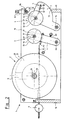
- the first exemplary embodiment of the printing press 1 shown here essentially consists of a machine frame 10 and three cylinders, namely a press cylinder 2, a printing plate cylinder 3 and a raster cylinder 4.
- the press cylinder 2 is by means of a front axle stub, of which here the front axle stub 23 is cut, mounted in an axle receptacle 11 in the machine frame 10 so as to be rotatable about an axis of rotation 26.
- the axis receptacle 11 within the machine frame 10 here consists of an upwardly open slot which extends in the vertical direction and through which the stub axles 23 and 24 (not visible here) can be guided upward in order to pull the impression cylinder out of the printing press 1 remove.
- the plate cylinder 3 and the raster cylinder 4 are not directly in the Machine frame 10, but at the upper ends of a pair of pivot arms 6 and 7, respectively.
- the pivot arm 6 for the plate cylinder 3 can be pivoted about a pivot axis 66 running parallel to the axis of rotation 36 of the plate cylinder 3 in the lower part of the machine frame 10.
- the plate cylinder 3 with its circumference 30 is in contact with the circumference 20 of the impression cylinder 2, ie in the working position.
- the pivoting of the swivel arm 6 in the direction of the working position can be limited by an adjustable stop 62.
- a measuring device here a dial gauge 9.
- the transmission between swivel arm 6 and dial gauge 9 takes place here by means of a feeler rod 91 which is guided horizontally through the machine 1 in the longitudinal direction of the swivel arm 6 to the dial gauge 9.
- the swivel arm 6 has a slot-shaped axle receptacle 61 for receiving the plate cylinder 3, into which the stub axles 33 of the plate cylinder 3 can be inserted from above.
- a pair of pivot arms 7 is also provided for holding the raster cylinder 4, these pivot arms 7 again being pivotable about a pivot axis 76 running parallel to the axis of rotation 46 of the raster cylinder 4.
- an axle receptacle 71 is again provided, in which the stub axles 43 of the raster cylinder 4 are inserted.
- a squeegee 5 for the ink application on the circumference 40 of the raster cylinder 4 is also arranged on the swivel arms 7.
- the squeegee 5, as is known per se, consists of a squeegee body 51 and a recessed therein towards the raster cylinder 4 protruding doctor blade 52.
- the doctor blade 5 can be pivoted about a pivot axis 56, which likewise runs parallel to the axis of rotation 46 of the screen cylinder 4.
- the printing press 1 shown in FIG. 1 also includes a pressure eccentric 8 which can be pivoted about a pivot axis 86 again running parallel to the axes of rotation 26, 36 and 46 of the cylinders 2, 3, 4.
- the three cylinders 2, 3 and 4 rest against one another with their peripheral surfaces 20, 30, 40.
- printing ink is supplied in the area of the doctor blade 5 and is distributed evenly on the screened circumference 40 of the screen cylinder 4 by the doctor blade 52.
- the raster cylinder 4 delivers the ink to the printing cylinder 3, more precisely its circumferential surface 30, from where the ink reaches a printing material guided around the circumference 20 of the impression cylinder 2.
- this can be reduced in diameter within the printing width by a corresponding amount in terms of its material thickness, which can happen with fully rubberized cliché cylinders, for example by burning out with a laser.
- the printing press 1 is driven solely by the impression cylinder 1, while the plate cylinder 3 and the raster cylinder 4 are set in rotation directly or indirectly by the impression cylinder 2 solely by friction.
- the necessary pressure force between the cylinders 2, 3 and 4 is caused by the pressure eccentric 8, which can be pivoted about its pivot axis 86 by means of an actuating lever 87 and brought into abutment with the part of the pivot arm 7 facing it.
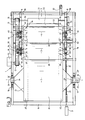
- FIG. 2 of the drawing shows the printing press 1 from FIG. 1 in its rest position, in which the cylinders 2, 3 and 4 are each at a distance from one another.
- the individual parts of the printing press reference is made to the description of FIG. 1.
- the printing plate cylinder 3 and / or the raster cylinder 4 can be removed from the printing machine 1 freely and upwards.
- a swiveling of the doctor blade 5 is required beforehand in order to remove the doctor blade 52 from the circumference 40 of the raster cylinder 4.
- the simple mounting of the cylinders 2, 3 and 4 can be seen in particular from the plan view of the printing press 1 shown in FIG. 3.
- the relatively large-sized impression cylinder 2 is first arranged, the stub axles 23 and 24 of which are each equipped with a roller bearing 23 'and 24'. These bearings 23 'and 24' are in turn used in the axle receptacles 11, the slots from above in the machine frame 10th are let in.
- the lower axle stub 23 in FIG. 3 is extended laterally beyond the adjacent part of the machine frame 10 and forms a connection 25 for any rotary drive, for. B. an electric motor or air motor with reduction gear.
- the axis of rotation 26 of the impression cylinder 2 is also indicated in the area of the stub axles 23 and 24.
- the impression cylinder 2 has a cylindrical circumference 20 which is delimited to the sides by the end faces 21 and 22 of the impression cylinder 2.
- the cliché cylinder 3 connects to the impression cylinder 2, which also carries a roller bearing 33 'and 34' on its stub axles 33 and 34. With these bearings 33 'and 34', the stub axles 33 and 34 are inserted into the axle receptacles 61 within the swivel arms 6. The swivel arms 6 can in turn be swiveled about the swivel axis 66.
- the cliché cylinder 3 of the raster cylinder 4 which is also equipped on its stub axles 43 and 44 with roller bearings 43 'and 44' and is used with these in corresponding axle receptacles 71 in the swivel arms 7.
- the pivot arms 7 can be pivoted about their pivot axis 76.
- peripheral surfaces 20, 30 and 40 With their peripheral surfaces 20, 30 and 40, the three cylinders 2, 3 and 4 lie against one another in the working position of the printing press 1 shown in FIG. As can also be seen from the figure, the peripheral surfaces 20, 30 and 40 each have front end peripheral regions 20 ', 30' and 40 ', which in particular ensure transmission of the rotary drive forces from the impression cylinder 2 to the printing cylinder 3 and the raster cylinder 4 . The required frictional engagement is achieved in that in the area of the peripheral end regions 20 ', 30' and 40 'between the individual cylinders 2, 3 and 4 always ensures sufficient contact.
- the squeegee 5 with its squeegee body 51, its squeegee knife 52 and its pivot axis 56 can again be seen to the right of the raster cylinder 4.
- a lock 55 is indicated in this figure below the doctor body 51 at the lower end of the pivot axis 56 in FIG. 3, by means of which the doctor blade 52 can be locked in its contact position on the circumference 40 of the raster cylinder 4.
- the locking 55 can be released manually.
- dial gauge 9 is visible from above, which detects the position of the plate cylinder 3 or its swivel arm 6 via the feeler rod 91.
- a second rotary drive which consists of a drive motor 13 which is attached to the side of the machine frame 10 and which can drive a drive roller 14 mounted in the machine frame 10.
- a toothed belt 12 Via the drive roller 14 and a deflection roller 15 mounted on the right end of the machine frame 10, a toothed belt 12 is connected to the outside, that is, in FIG. 3, teeth pointing upwards.
- the stub axles 34 and 44 of the two cylinders 3 and 4 are extended in the region of their end faces 32 and 42 facing the toothed belt 12 and each carry a gear wheel 35 and 45, respectively, which can be brought into engagement with the toothed belt 12.
- the printing press 1 is preferably constructed in such a way that the gear wheels 35 and 45 are exposed above the toothed belt 12 in the working position of the printing press 1 shown in FIG. 3, ie do not engage its teeth. Conversely, however, the gears 35 and 36 come into engagement with the toothed belt 12 when the cylinders 3 and 4 are pivoted to the right and down in their rest position. In this position, the two cylinders 3 and 4 can be set in rotation by the toothed belt 12 in order to be able to clean the cylinders 3 and 4 without removing them from the printing press 1. This rotary drive with the motor 13 and the toothed belt 12 has no function for the printing process.
- the cylinders 2 to 4 are pressed against one another and the cylinders 3 and 4 are pivoted between their working position and their rest position manually.
- This version of the printing press 1 is therefore particularly suitable for use as a test printing press, which can be used above all to select an optimal screen of the screen cylinder 4.
- the embodiment of the printing press 1 shown in FIG. 4 of the drawing is more mechanized, with manual operation being replaced by remotely operable means.
- FIG. 4 In terms of its structure with regard to cylinders 2, 3 and 4, as well as their mounting and pivotability, the design of the printing press shown in FIG. 4 corresponds 1 the exemplary embodiment previously explained with reference to FIGS. 1 to 3. With regard to the individual parts of the printing press 1 according to FIG. 4, reference is made to the previous explanation of FIGS. 1 to 3.
- the printing press 1 in FIG. 4 is designed with a somewhat higher machine frame 10 and the swivel arm 7 of the raster cylinder 4 is designed with an extension 70 downward beyond the swivel axis 76.
- the swivel arm 7 becomes a two-armed lever, at the lower end of which the piston rod 81 is articulated to a piston-cylinder unit 80 arranged horizontally in the machine frame 10.
- the piston-cylinder unit 80 also has a cylinder 82 in which a piston (not visible here), which is connected to the piston rod 81, is guided. With its left end, the piston-cylinder unit 80 is fastened to a side wall of the machine frame 10 by means of a bearing block 83.
- two lines 85 are provided, which lead from the piston-cylinder unit 80 to a pressure control unit and actuation unit 84 attached outside the machine frame 10.
- the actuating force of the piston-cylinder unit 80 can be set by means of this unit 84 and its function can be controlled.
- the piston rod 81 is extended from the cylinder 82.
- the swivel arm 7 is pivoted counterclockwise with the raster cylinder 4 in contact with the plate cylinder 3 and this in turn in contact with the impression cylinder 2.
- the pressure force of the cylinders 2, 3 and 4 with each other can be adjusted by regulating a certain pressure of the pressure medium with which the cylinder 82 of the piston-cylinder unit 80 is sent to be set as needed.
- the pivoting of the swivel arm 6 can either be done separately by hand, as can be seen in FIG. 4, or a loose mechanical coupling can also be provided between the two swivel arms 6 and 7, which ensures that the swivel arms 6 and 7 are pivoted together , but not hindered their fine adjustment. Due to its greater mechanization, the design of the printing press 1 according to FIG. 4 is particularly suitable for integration into a printing line or other production line.
- FIG. 5 Figures 5 and 6 of the drawing each show an embodiment for a special screen cylinder 4 and plate cylinder 3, which are specifically intended for trial printing.
- the screen cylinder 4 shown in a development in FIG. 5 has a plurality of, here in total eight, strips 47 of different screening running in the circumferential direction on its cylinder jacket surface or circumferential surface 40 lying in the plane of the drawing.
- the running direction of the raster cylinder 4 is indicated by the direction arrow drawn in the right part of FIG. 5.
- Each of the parallel strips 47 has a specific, standardized grid, the different grids corresponding to a standard grid series used in flexographic printing.
- the screening from stripes to stripes 47 is graduated from one end face 41 to the other end face 42 of the raster cylinder 4, becoming ever finer.
- Figure 6 shows - also in a development - an embodiment for a plate cylinder 3, which is formed here with strips 37 running transversely to the circumferential direction of different grid.
- a plate cylinder 3 which is formed here with strips 37 running transversely to the circumferential direction of different grid.
- strips 37 running transversely to the circumferential direction of different grid.
- a more or less large number of different grids can be accommodated on a single plate cylinder.
- some typical raster designations that are common in flexographic printing are given in the individual strips 47.
- the running direction of the plate cylinder 3 is again indicated here by an arrow drawn in the right part of FIG.
- the raster in the plate cylinder 3, seen in the circumferential direction increases or decreases gradually from strip to strip 37.
- a printed image results on the printing material, which is composed of a multiplicity of squares or rectangles, each one of which the possible combinations of the screen cylinder grid and the cliché grid corresponds.
- the optimal combination of screen cylinder screening and cliché screening can be determined very easily and quickly. In practice, for example, for a given cliché screening, the optimal screening for the screen can be done with minimal effort cylinders are determined.
- the screen cylinder is then used in production, which has the screen over its entire circumference, which has proven to be optimal in test printing.
- the individual strips should have a width of at least two centimeters, ie that an area of at least four square centimeters is available for the assessment of each combination of screen cylinder screening and cliché screening .
- the use of wider strips allows a better assessment of the test print results, but on the other hand reduces the number of possible strips per cylinder or requires larger cylinders.
Landscapes
- Engineering & Computer Science (AREA)
- Mechanical Engineering (AREA)
- Screen Printers (AREA)
Priority Applications (1)
| Application Number | Priority Date | Filing Date | Title |
|---|---|---|---|
| EP89121406A EP0428767A1 (fr) | 1989-11-18 | 1989-11-18 | Machine d'impression rotative flexographique |
Applications Claiming Priority (1)
| Application Number | Priority Date | Filing Date | Title |
|---|---|---|---|
| EP89121406A EP0428767A1 (fr) | 1989-11-18 | 1989-11-18 | Machine d'impression rotative flexographique |
Publications (1)
| Publication Number | Publication Date |
|---|---|
| EP0428767A1 true EP0428767A1 (fr) | 1991-05-29 |
Family
ID=8202140
Family Applications (1)
| Application Number | Title | Priority Date | Filing Date |
|---|---|---|---|
| EP89121406A Withdrawn EP0428767A1 (fr) | 1989-11-18 | 1989-11-18 | Machine d'impression rotative flexographique |
Country Status (1)
| Country | Link |
|---|---|
| EP (1) | EP0428767A1 (fr) |
Cited By (8)
| Publication number | Priority date | Publication date | Assignee | Title |
|---|---|---|---|---|
| EP1099548A2 (fr) * | 1999-05-28 | 2001-05-16 | Clemens Ditzel | Dispositif d'impression d'essais pour imprimer et/ou pour revêtir des materiaux en bande |
| WO2003016056A1 (fr) * | 2001-08-15 | 2003-02-27 | Integrity Engineering, Inc. | Dispositif d'enduction d'encre |
| US7275482B2 (en) | 2004-10-28 | 2007-10-02 | Integrity Engineering, Inc. | Ink proofer arrangement including substrate roll support and tensioner and method of using |
| US7316182B2 (en) | 2001-08-15 | 2008-01-08 | Integrity Engineering, Inc. | Ink proofer arrangement including light source for curing ink |
| US8539880B2 (en) | 2005-05-10 | 2013-09-24 | Probity Engineering, Llc | Hand proofer tool |
| US8720335B2 (en) | 2007-04-24 | 2014-05-13 | Probity Engineering, Llc | Offset hand proofer tool |
| US8973497B2 (en) | 2007-04-24 | 2015-03-10 | Probity Engineering, Llc | Flexographic proofing tools and methods |
| CN108162590A (zh) * | 2018-02-24 | 2018-06-15 | 广东东方精工科技股份有限公司 | 一种印刷机的网纹辊更换机构 |
Citations (2)
| Publication number | Priority date | Publication date | Assignee | Title |
|---|---|---|---|---|
| DE1561023A1 (de) * | 1967-05-26 | 1970-03-12 | Kroenert Max Maschf | Vorrichtung zum Abheben von Formzylinder und Farbwerk bei Rotationsdruckmaschinen |
| FR2135666A1 (fr) * | 1971-05-06 | 1972-12-22 | Spazzapan Mariano |
-
1989
- 1989-11-18 EP EP89121406A patent/EP0428767A1/fr not_active Withdrawn
Patent Citations (2)
| Publication number | Priority date | Publication date | Assignee | Title |
|---|---|---|---|---|
| DE1561023A1 (de) * | 1967-05-26 | 1970-03-12 | Kroenert Max Maschf | Vorrichtung zum Abheben von Formzylinder und Farbwerk bei Rotationsdruckmaschinen |
| FR2135666A1 (fr) * | 1971-05-06 | 1972-12-22 | Spazzapan Mariano |
Cited By (10)
| Publication number | Priority date | Publication date | Assignee | Title |
|---|---|---|---|---|
| EP1099548A2 (fr) * | 1999-05-28 | 2001-05-16 | Clemens Ditzel | Dispositif d'impression d'essais pour imprimer et/ou pour revêtir des materiaux en bande |
| EP1099548A3 (fr) * | 1999-05-28 | 2002-11-27 | Clemens Ditzel | Dispositif d'impression d'essais pour imprimer et/ou pour revêtir des materiaux en bande |
| WO2003016056A1 (fr) * | 2001-08-15 | 2003-02-27 | Integrity Engineering, Inc. | Dispositif d'enduction d'encre |
| US6814001B2 (en) | 2001-08-15 | 2004-11-09 | Integrity Engineering, Inc. | Ink proofer |
| US7316182B2 (en) | 2001-08-15 | 2008-01-08 | Integrity Engineering, Inc. | Ink proofer arrangement including light source for curing ink |
| US7275482B2 (en) | 2004-10-28 | 2007-10-02 | Integrity Engineering, Inc. | Ink proofer arrangement including substrate roll support and tensioner and method of using |
| US8539880B2 (en) | 2005-05-10 | 2013-09-24 | Probity Engineering, Llc | Hand proofer tool |
| US8720335B2 (en) | 2007-04-24 | 2014-05-13 | Probity Engineering, Llc | Offset hand proofer tool |
| US8973497B2 (en) | 2007-04-24 | 2015-03-10 | Probity Engineering, Llc | Flexographic proofing tools and methods |
| CN108162590A (zh) * | 2018-02-24 | 2018-06-15 | 广东东方精工科技股份有限公司 | 一种印刷机的网纹辊更换机构 |
Similar Documents
| Publication | Publication Date | Title |
|---|---|---|
| EP0563007B1 (fr) | Machine à imprimer en creux | |
| DE3146223C2 (de) | Feucht-Farbwerk für Offsetdruckmaschinen | |
| DE69122688T2 (de) | System mit mehrfachen Farbwalzen für Flexodruckwerken | |
| EP0047861A1 (fr) | Dispositif d'encrage comprenant un cylindre d'encrage d'un mouvement de va-et-vient | |
| DE2718299A1 (de) | Rotations-druckmaschine | |
| DE3143781C2 (de) | Vorrichtung zum Zuführen einer Flüssigkeit auf die Zylinder einer Rotationdruckmaschine | |
| DE2703424C2 (de) | Farbwerk für Offset-Druckmaschinen | |
| EP0116176B1 (fr) | Dispositif d'encrage | |
| DE3938405C1 (en) | Printing machine for rotary flexoprinting - has rotary drive on pressure cylinder, with friction driving stencil and raster cylinders | |
| DE69405824T2 (de) | Farbwerk für Druckmaschinen | |
| DE2711553A1 (de) | Farbkasten fuer offset- oder hochdruckmaschinen | |
| EP0602431A1 (fr) | Dispositif de racle d'essuyage | |
| EP0428767A1 (fr) | Machine d'impression rotative flexographique | |
| DE69400707T2 (de) | Einrichtung zum verstellen des abstandes zwischen zylinderachsen in einer druckmaschine | |
| DE2411691C3 (de) | Kombinierte Mehrfarben-Offset- und Stichdruckrotationsmaschine | |
| DD141068A5 (de) | Test-vorrichtung fuer formzylinder zur be-oder verarbeitung bandfoermigen materials | |
| DE2949957C2 (de) | Druckeinheit für eine Rollen-Rotations-Offsetdruckmaschine | |
| DE3213540C2 (de) | Rotations-Druckmaschine für den Druck mit hoch viskosen Farben | |
| EP0131103A2 (fr) | Dispositif d'encrage pour machines d'impression typographique et machines d'impression offset | |
| DE3539254A1 (de) | Offset-druckerpresse | |
| EP0894049B1 (fr) | Machine a imprimer a tampon encreur | |
| DE3637460A1 (de) | Druckplattenbefeuchtungsvorrichtung | |
| DE2903415A1 (de) | Siebdruckmaschine mit grossem drucktisch | |
| DE3638308C2 (fr) | ||
| EP1005982A1 (fr) | Dispositif pour échanger des rouleaux ou cylindres dans une machine à imprimer |
Legal Events
| Date | Code | Title | Description |
|---|---|---|---|
| PUAI | Public reference made under article 153(3) epc to a published international application that has entered the european phase |
Free format text: ORIGINAL CODE: 0009012 |
|
| AK | Designated contracting states |
Kind code of ref document: A1 Designated state(s): AT BE CH ES FR GB IT LI NL |
|
| 17P | Request for examination filed |
Effective date: 19910705 |
|
| 17Q | First examination report despatched |
Effective date: 19930812 |
|
| STAA | Information on the status of an ep patent application or granted ep patent |
Free format text: STATUS: THE APPLICATION IS DEEMED TO BE WITHDRAWN |
|
| 18D | Application deemed to be withdrawn |
Effective date: 19931223 |