EP0428246A1 - Dispositif pour régler l'écoulement de liquides et méthode pour fabriquer ce dispositif - Google Patents
Dispositif pour régler l'écoulement de liquides et méthode pour fabriquer ce dispositif Download PDFInfo
- Publication number
- EP0428246A1 EP0428246A1 EP90307890A EP90307890A EP0428246A1 EP 0428246 A1 EP0428246 A1 EP 0428246A1 EP 90307890 A EP90307890 A EP 90307890A EP 90307890 A EP90307890 A EP 90307890A EP 0428246 A1 EP0428246 A1 EP 0428246A1
- Authority
- EP
- European Patent Office
- Prior art keywords
- liquid
- control unit
- partial
- liquid outflow
- partial members
- Prior art date
- Legal status (The legal status is an assumption and is not a legal conclusion. Google has not performed a legal analysis and makes no representation as to the accuracy of the status listed.)
- Ceased
Links
Images


Classifications
-
- A—HUMAN NECESSITIES
- A61—MEDICAL OR VETERINARY SCIENCE; HYGIENE
- A61M—DEVICES FOR INTRODUCING MEDIA INTO, OR ONTO, THE BODY; DEVICES FOR TRANSDUCING BODY MEDIA OR FOR TAKING MEDIA FROM THE BODY; DEVICES FOR PRODUCING OR ENDING SLEEP OR STUPOR
- A61M25/00—Catheters; Hollow probes
-
- A—HUMAN NECESSITIES
- A61—MEDICAL OR VETERINARY SCIENCE; HYGIENE
- A61M—DEVICES FOR INTRODUCING MEDIA INTO, OR ONTO, THE BODY; DEVICES FOR TRANSDUCING BODY MEDIA OR FOR TAKING MEDIA FROM THE BODY; DEVICES FOR PRODUCING OR ENDING SLEEP OR STUPOR
- A61M5/00—Devices for bringing media into the body in a subcutaneous, intra-vascular or intramuscular way; Accessories therefor, e.g. filling or cleaning devices, arm-rests
- A61M5/14—Infusion devices, e.g. infusing by gravity; Blood infusion; Accessories therefor
- A61M5/142—Pressure infusion, e.g. using pumps
- A61M5/145—Pressure infusion, e.g. using pumps using pressurised reservoirs, e.g. pressurised by means of pistons
- A61M5/148—Pressure infusion, e.g. using pumps using pressurised reservoirs, e.g. pressurised by means of pistons flexible, e.g. independent bags
- A61M5/152—Pressure infusion, e.g. using pumps using pressurised reservoirs, e.g. pressurised by means of pistons flexible, e.g. independent bags pressurised by contraction of elastic reservoirs
-
- A—HUMAN NECESSITIES
- A61—MEDICAL OR VETERINARY SCIENCE; HYGIENE
- A61M—DEVICES FOR INTRODUCING MEDIA INTO, OR ONTO, THE BODY; DEVICES FOR TRANSDUCING BODY MEDIA OR FOR TAKING MEDIA FROM THE BODY; DEVICES FOR PRODUCING OR ENDING SLEEP OR STUPOR
- A61M5/00—Devices for bringing media into the body in a subcutaneous, intra-vascular or intramuscular way; Accessories therefor, e.g. filling or cleaning devices, arm-rests
- A61M5/14—Infusion devices, e.g. infusing by gravity; Blood infusion; Accessories therefor
- A61M5/141—Infusion devices, e.g. infusing by gravity; Blood infusion; Accessories therefor with capillaries for restricting fluid flow
Definitions
- the present invention relates to a liquid outflow control unit capable of controlling the flow rate of the injected liquid and used in a continuous liquid injector or the like for sequentially injecting into a desirable portion of a human body a liquid such as a liquid medicine accommodated within a liquid accommodating portion.
- a liquid accommodated in an injector is manually or automatically supplied into the body through a needle or a catheter.
- a liquid in an instillator is naturally or automatically supplied into the body.
- Such continuous injection of the liquid takes a few minutes or a few hours.
- a needle or the like is connected continuously to a syringe or the like, and this may cause pain to the patient or limit his or her actions during the injection. It may also be necessary for the operator, who may be a doctor or a nurse, to hold a syringe or check the amount of liquid given by an intravenous drip injection, making the injection procedure a troublesome task.
- All of these conventional continuous liquid medicine injectors therein incorporate a balloon or a bag made of an elastic material.
- An inlet from which a liquid medicine is put into the balloon is provided in one end of the balloon, and an outlet from which the liquid medicine is forced out of the balloon is provided in the other end of the balloon.
- the inlet is provided with a check valve which allows the liquid medicine to flow into the balloon but does not permit it to flow out of the balloon.
- the liquid medicine accommodated in the balloon is forced out of its outlet due to the contraction of the balloon against the human body through an instrument such as a needle inserted into the body.
- the outflow control of a liquid medicine in Japanese Patent Laid-Open No. 56-102252 is provided by a very thin flow control element provided in a fluid path (mouth) which fluid communicates between the inside and outside of the balloon.
- the flow control element includes a somewhat short linear pipe.
- a change in the flow is considered to be performed by changing the length and inner diameter of the pipe although they are not specifically described.
- it is considered to be virtually impossible to increase the length of the flow control element sufficiently because it is incorporated in the flow path and also to extremely reduce the inner diameter from a standpoint of manufacture.
- a liquid medicine is required to be supplied in very small amounts to the human body for a long time depending on the kind of the medicine, the flow control element cannot sufficiently satisfy such requirement.
- the flow of liquid medicine is controlled by suitably changing the diameter of through holes formed in the wall of the tube-like body on which the balloon is mounted or by employing a diaphragm which varies the area of the inner diameter of the outlet in the tube-like body in accordance with the inner pressure of the balloon.
- control of the diameter of the through hole formed in the tube wall does not ensure sufficient control of the flow rate due to the thinness of the tube wall.
- the required diaphragm is difficult to manufacture and hence unsuitable for mass production, and its use is, therefore, not practical.
- control of the flow of liquid medicine is provided by varying the diameter of a thin tube (thin hole) formed so as to extend axially of the tube wall of a catheter.
- the injector proposed in Japanese Patent Laid-Open ,vo. 62-11465 incorporates therein a liquid flow regulating valve in the liquid outlet, and flow control is provided by controlling the restricting ratio of tne flow regulating valve.
- precise control is also difficult in this injector.
- An object of the present invention is to provide a liquid outflow control unit which has a siniple structure and which ensures precise control of the outflow of liquid.
- a liquid outflow control unit comprises a plurality of partial members of a synthetic resin to which the control unit is divided along tne direction of flow of a liquid, at least one of the partial members having a groove on a joined face thereof to form a part of a small slow control path having one end which fluid communicates with a liquid inlet and the other end which fluid communicates with a liquid outlet.
- the small flow control path is preferably composed of a groove provided in one flat surface of one member and a flat surface of the other member joined to the flat surface of the one member.
- both the members each may include a groove.
- liquid leakage prevention means which includes a combination of a rib and a groove is preferably formed around the small flow control path.
- a communication hole which fluid communicates with the outer surface of the liquid outflow control unit is preferably formed on a part of the side of the liquid inlet in the small flow control path.
- a method of manufacturing a liquid outflow control unit comprises the steps of forming from a synthetic resin a plurality of partial members to which the control unit is divided along the direction of flow of a liquid, at least one of the partial members having a groove on a joined face thereof to form a part of a small flow control small path, and joining those partial members together closely on their joined faces.
- the partial members are preferably formed using the injection molding. While the junction is preferably formed using ultrasonic adhesion.
- the liquid outflow control unit having the above structure according to the present invention is easily manufactured by forming partial members of a synthetic resin using injection molding or the like and joining them together to thereby ensure mass production and stabilized quality. Since the small flow control path is formed by the joined surfaces of the partial members, the small path may take a proper form, for example, of being straight of course, crooked or zigzag. Control of the flow of liquid is provided very easily by setting the inner diameter and length of the small path to corresponding predetermined ones.
- Figs. 1 - 3 shows one embodiment of a liquid outflow control unit according to the present invention applied to a continuous liquid injector.
- the continuous liquid injector 10 in the particular embodiment includes a substantially cylindrical liquid outflow control unit 20 made of a synthetic resin.
- the control unit is preferably made of a transparent or translucent material from the viewpoint of affording visibility of the interior thereof.
- a liquid receiving portion 13 On which a syringe 12 serving as a liquid supply means can be mounted.
- a liquid outflow prevention means 14 for preventing the liquid, which has been injected into the control unit 20 from the syringe 12, from flowing out of the liquid receiving portion 13.
- This prevention means 14 may be a check valve which permits the flow of the liquid only in the direction of allow P or a one-way cock which can open/close a flow passage 13A in the liquid receiving portion 13. Any suitable check valve or one- way cock available commercially may be used.
- a small flow control path 21 which has a larger liquid inlet 22 at its right- hand end which fluid communicates with the liquid receiving portion 13 and the other end, namely, left-hand end which includes a liquid outlet which constitutes an end of the small path and which has the same diameter as the small path.
- the small path 21 is formed zigzag to ensure a predetermined length.
- the small path 21 is, for example, several 10 ⁇ m to several 100 ⁇ m in diameter.
- a plurality of communication holes 24 which fluid communicate with the outer surface of the liquid flow control unit 20 are formed in part of the liquid receiving portion 22 side of the small flow control path 21.
- peripheral grooves 25 are formed at the opening ends of the communication holes 24 on the control unit 20 which fluid communicate with the communication holes 24 to thereby facilitate the outflow and inflow of a liquid through the communication path 24.
- Figs. 2 and 3 illustrate the partial members of the liquid outflow control unit 20 and the joined members.
- the liquid outflow control unit 20 is divided into a plurality of substantially equal partial members (two partial members 20A, 20B in the particular embodiments) in the direction of flow of the liquid or in the direction of allow P in Fig. 1.
- These partial members 20A and 20B are separately formed of a synthetic resin by injection molding, for example.
- the synthetic resin includes a silicone resin, acryl, polycarbonate (PC), polyethylene (PE), polypropylene (PP), polyacetal (POM), polyamide (PA), fruororesin, bakelite, or any other thermoplastic or thermosetting resin.
- the material is preferivelyably thermoplastic, suitable for injection molding, stable in a liquid and slightly transparent; for example, a polycarbonate.
- the partial members 20A and 20B have grooves 21A and 21B to form the small zigzag flow control path 21. They also have grooves 22A, 228 and 23A, 23B at one end and the other end of the grooves 21A and 21B to form liquid inlet and outlet 22 and 23, respectively. Furthermore, the partial members 20A and 20B have grooves 24A, 24B and 25A, 25B to form communication holes 24 and peripheral grooves 25, respectively.
- the partial members 20A and 20B are joined together such that their symmetrical patterns face and coincide on the joined face 26 and the joined faces 26A and 268 of the partial members 20A and 208 are joined by proper means, which preferably includes ultrasonic adhesion or may be other means such as bonding if inflow of an adhesive into the small path 21, for example, is prevented effectively.
- proper means which preferably includes ultrasonic adhesion or may be other means such as bonding if inflow of an adhesive into the small path 21, for example, is prevented effectively.
- a cylindrical rubber-like elastic membrane 31 is mounted on the control unit 20 in such a manner as to cover all the communication holes 24 in the control unit 20.
- the rubber-like elastic membrane 31 is fixedly attached to the outer periphery of the control unit 20 in an air-tight manner at two end portions 31A thereof, an intermediate portion 313 thereof being isolatable from the outer periphery of the control unit 20.
- the rubber-like elastic membrane 31 is preferable made of an elastic material which is sufficiently wear-resistant and tough and not readily damaged by external force. In particular, a transparent or translucent material is preferably employed. Suitable materials of the elastic membrane 31 include a silicone rubber and a latex rubber which are available commercially.
- the rubber-like elastic membrane 31 is inflatable with the liquid which flows thereinto through the communication holes 24, as shown by the dot-line in Fig. 1.
- the inflated membrane 31 constitutes a liquid pressurizing means.
- the interior of the inflated membrane 31 and that of the control unit 20 constitute a liquid accommodating portion 35.
- a cock 40 Detachably provided at the outer end portion, at the left side in Fig. 1, of the liquid outflow control unit 20 is a cock 40 which serves as an opening/closing means.
- the cock 40 includes a body 41 with a flow passage 41A formed therein, the body 41 being attached to the other end of the control unit 20 so as to be in fluid communication with the medicine outlet 23, and a knob 42 with a communication hole 42A which can communicate with the flow passage 41A formed therein, the knob 42 being pivotally provided in the body 41.
- the flow passage 41A can be blocked or made to communicate with the communication hole 42A by pivoting the knob 42.
- the communi cation hole 42A is disposed perpendicular to the flow passage 41A to block it. Turning of the knob 42 through 90 degrees from the state illustrated opens the flow passage 41A.
- a needle 50 which is an instrument inserted into the human body is detachably mounted on the body 41 of the cock 40 through an elastic connecting tube 47 having connectors 45 and 46 at its ends.
- the needle 50 available commercially, includes a mounting portion 51 which can be mounted on one connector 46 of connection tube 47, and a needle 52 attached in the mounting portion 51.
- a transparent cover 38 which covers a rubber-like elastic membrane 31 inflated in the form of a sphere, is mounted, if necessary.
- the cover 38 has a band 39 through which the cover 38 is mounted on the arm or the like of a patient.
- the cover 38 has the functions of protecting the rubber-like elastic membrane 31 in an inflated state and of fastening the injector onto the patient.
- the cock 40 as the opening/closing means, is mounted on one end of the control unit 20 of the continuous liquid injector 10, and the knob 42 of the cock 40 is operated as illustrated in Fig. 1 to close it.
- the syringe 12 which is a liquid supply means, is inserted into the liquid receiving portion 13 of the control unit 20, and a predetermined amount of liquid accommodated within the syringe 12 is forced out of it in the direction of arrow P.
- the liquid is forced into the liquid inlet 22 through the liquid outflow prevention means 14.
- the cock 40 mounted on the liquid outlet 23 side of the control unit 20 is in a closed state, the outflow of the liquid from the liquid outlet 23 is prevented.
- This causes the liquid to flow into the rubber-like elastic membrane 31 through the inlet 22 in the control unit 20 from the communication holes 24 formed in the small path 21, inflating the elastic membrane 31 in the form of a sphere.
- the contracting force of the elastic membrane 31 which is the reaction force caused by the inflation makes the rubber-like elastic membrane 31 serve as a pressurising means which applies a predetermined amount of pressure to the liquid.
- the interior of the control unit 20 and that of the inflated elastic membrane 31 constitute the liquid accommodating portion 35.
- liquid filling in the rubber-like elastic membrane 31 is prevented from flowing back out of the liquid receiving portion 13 by the action of the liquid outflow prevention means 14 provided in the liquid receiving portion 13.
- the same type of liquid or physiological salt solution may be injected in the control unit 20 beforehand.
- the control unit 20 may be made upright with the liquid receiving portion 13 located up after the injection of the liquid. In this way, bubbles in the rubber-like elastic membrane 31 and the control unit 20 float up in the liquid receiving porton 13 of the control unit 20, so that the air is readily discharged through a tube vent (not shown) inserted into the liquid receiving portion 13 by opening the liquid outflow prevention means 14.
- the needle 50 which is an instrument mounted on the human body, is mounted on the cock 40 through the connection tube 45 when required. This needle 50 is then inserted into the human body, thereby completing the preparation of injection of liquid into the human body.
- the flow passage 41A is opened by turning the knob 42 of the cock 40 to thereby make the hole 42A communicate with the flow passage 41A.
- This causes the liquid, accommodated in the liquid accommodating portion 35 and pressurized by the rubber-like elastic membrane 31 as pressurizing means, to flow into the small path 21 in the liquid outflow control unit 20 via the peripheral grooves 25 and communication holes 24.
- the liquid in the liquid outflow control unit 20 flows into the flow passage 41A of the cock 40 at a certain flow rate, i.e., in an amount determined by the inner diameter and length of the small path 21.
- the liquid flows through the flow passage 41A in the direction of allow T, then into the human body (not shown) through the connection tube 47 and the needle 50.
- the flow liquid outflow control unit 20 the flow of the liquid lasts for a predetermined period of time in spite of the pressure applied to the liquid by the inflated rubber-like elastic membrane 31.
- the time during which the flow of the liquid lasts is determined by the amount of liquid injected, its viscosity, the elasticity of the rubber-like elastic membrane 31, the inner diameter and length of the small path 21 in the liquid outflow control unit 20, the pressure in the human body into which the liquid is to be injected, and so on. In practice, the details are determined by measuring the time required for a certain type of liquid to be forced out of each continuous individual liquid injector 10.
- This embodiment has the following advantages.
- the liquid outflow control unit 20 employs the small path 21 which has an accurate inner diameter formed by using an accurately worked mold.
- controlling of the flow rate of liquid with high accuracy is ensured by suitably setting the inner diameter and length of the path 21.
- setting of the inner diameter and length of the small path 21 is possible by working the mold accurately. In consequence, easy mass production is attained, and the manufacturer cost of the continuous liquid injector 10 can be reduced.
- the small path 21 can be formed long in a zigzag manner, the diameter of the small path 21 can be enlarged as its length is increased in the control of the same flow to thereby cause no problems such as clogging of the path.
- the embodiment of the continuous liquid injector 10 has both the functions of accommodating and pressurizing/injecting the liquid. In consequence, it is small in size and has a simple structure. It also ensures easy handling of the injector. It does not therefore limit the actions of a patient, and alleviates the operator's task and time during which the operator is restricted. Furthermore, a provision of the liquid outflow prevention means 14 in the liquid receiving portion 13 and the hermetical sealing structure of the overall continuous liquid injector 10 ensure that no air enters into the injector 10 until the rubber-like elastic membrane 31 is completely contracted once air has been vented out of it.
- grooves 21A may be provided on only one of the joined faces 26A and 26B of the partial members 20A and 20B (the joined face 26A of the partial member 20A in the particular embodiment) in order to form the small path 21 in the liquid outflow control unit 20.
- the groove 24A for the communication holes 24 may be provided at only one partial member 20A, while the joined face 26B of the other partial member 20B is formed flat.
- one joined face, for example, 26B of the partial members 20A and 20B is flat, so that both the members 20A and 20B are easily aligned and joined rapidly.
- liquid leakage prevention means 60 may be provided on each side of the small path 21 or the groove 21A in only the partial member 20A.
- the liquid leakage prevention means 30 includes a rib 61 provided on the side of one partial member 20A and a recess 62 provided on the other partial member 20B so as to be substantially complementary in shape to the rib 61.
- the rib 61 includes a pair of longitudinal subribs 61A one provided on each side of the groove 21A and extending in the direction of flow of a liquid in order to prevent radial leakage of the medicine and a plurality of transverse subribs 61B provided between the longitudinal subribs 61A and between the grooves 24A to form the respective communication holes 24 except at the grooves 21A in order. to prevent leakage of a liquid in the direction of flow of the liquid.
- the groove 21A may be formed zigzag so as to form three groove portions in the middle portion of the control unit 20 as shown in Fig. 1 or Fig. 4, of course. While in that case, the rib 61 and groove 62 are provided so as to prevent the leakage of the medicine from each groove 21A, the longitudinal subribs 61A between adjacent grooves 21A may be formed as a common single one. Conversely, a rib 61 and a groove 62 may be provided on the partial members 20B and 20A, respectively. Alternatively, no grooves may be provided on one partial member while only a rib may be provided on only the other partial member.
- both the partial members each may have a rib so as to reduce the joined area to eliminate a possible small opening between both the members.
- Only one groove 21A may be provided as one path groove, as shown, depending on the flow amount of the liquid. It is not necessarily zigzag.
- the control of the flow amount of the liquid is determined by the cross-sectional area of the groove 21A orthogonal to the axis of groove 21A and the length of the groove, the cross-sectional area and length of the groove may be determined in manufacturing when required.
- the liquid receiving inlet 22 may not directly be connected to the flow control small path 21 and communicates with the small path 21 via the outer periphery of the liquid flow control unit 20 and the rubber-like elastic membrane 31 and through the peripheral grooves 25 and communi cation holes 24.
- the same effects as those produced by the first embodiment are obtained.
- the communication holes 24 each substantially constitute a liquid inlet for the small path 21.
- the pressurizing means is not limited to the rubber-like elastic membrane 31 and other pressurizing means may be applicable.
- the position where the rubber-like elastic membrane 31 is attached to the liquid outflow control unit 20 is not limited to a position in the middle portion of the control unit 20. It may be at one end of the control unit 20, as shown in Fig. 7. In this case, the liquid receiving portion 13 is attached to the other end of the elastic membrane 31. No peripheral grooves and communication holes are formed on the control unit 20. In Fig. 8, of course, the other side of the elastic membrane 31 may be closed to form a balloon-like rubber-like elastic membrane 31 while the liquid medicine receiving portion 13 may diverge from the middle portion of the control unit 20 such that the path 13A communicates with the small path 21.
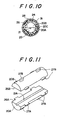
- Means for adhering the partial members 20A and 20B of the control unit 20 each other is not limited to the aforementioned ultrasonic adhesion or bond, but can be employed as shown in Figs. 9 to 13, in which the partial members 20A, 20B made of synthetic resin are under the operation of a insert resin-molding by means of injection molding or the like.
- the partial members 20A, 20B shown in the enbodiment of Figs. 9 to 13 are of the members only for controlling the outflow amount of the liquid.
- a groove 21A having the shape of character V is formed on a joined face 26A of one partial member 20A, while on a joined face 26B of the other partial member 208 no grooves are formed.
- the small flow control path 21 consisted of the groove 21A and the joined face 26B has a cross sectional configuration of a equilateral triangle or a right angled triangle, in which one edge is set at the length of e.g., several 10 ⁇ m to several 100 ⁇ m and the control path 21 is a straight path having no bend portions.
- each partial member 20A, 20B has such a plurality of projection 27A, 27B that can strengthen the adhesion with a resin for molding under the insert resin molding.
- the partial members 20A and 20B face and coincide on the joined faces 26A and 26B, and subsequently set in a cavity for injection molding.
- a connecting member C is so formed as to be one shape by the injection molding that it can, as shown in fig. 9, cover the outer periphery of the partial members 20A, 20B and cylindrically extend form one end of the joined partial members 20A, 20B.
- the connecting member C has a plurality of communication holes 24 in its cylindrical portion and communication grooves 28 capable of communicating the communication holes 24 with one another along the axial direction.
- liquid outflow control unit 20 in this embodiment can be obtained by that pre-molded partial members 20A, 20B made of synthetic resin are uniformly resin-molded with the connecting member 20C.
- the outer periphery of the connecting member 20C in the control unit 20 is substantially covered with the rubber-like elastic membrane 31 so as to hide on whole the communication holes 24.
- Fixed in the liquid receiving portion 13 is a liquid outflow prevention means 14 and mounted at a end portion 12 having a large diameter in the connecting member 20C.
- the interior of the large diameter of the connecting member 20C mounted on the liquid receiving portion 13 is used to be a liquid inlet 22, while at the opposite end portion of the inlet 22, a small flow control path 21 consisted of both the partial members 20A, 20B is used to be a liquid injecting portion 23.
- the connecting operation shall be easier due to uniformly riiolding the partial members 20A, 20B by means of the connecting member 20C. Another effect can be so expected that the liquid leakage from the joined face 26 between the two partial members 20A and 20B.
- the partial members 20A, 208 inserted into are not limited to be made of synthetic resin, but may be of a cut production made from the metal, a super alloy and a sintered production such as ceramics. From a practical standpoint, a resin production may be mass produced in a cheaper price, while a metal production may attain precise forming of the small path 21 to thereby control the flow amount in accurate.
- the material of the connecting member 20C is preferably of the same as that of the members 20A, 20B, but if the materials of both the members 20A, 20B and 20C can be welded one another, such the materials are well used.
- the liquid accommodating portion 35 need not be constituted by the interiors of the expanded rubber-like membrane 31 and control unit 20. Briefly, it may be provided anywhere as long as it can accommodate a liquid and its shape is not important.
- the shape of the liquid outflow control unit 20 is not limited to a cylindrical one, but may have another form, for example, of a prism or a flat.
- the control unit 20 need not be constituted by two substantially identical partial members as in the particular embodiment, but may be constituted by three or more partial members. In this case, a small path 21 is only required to be formed on at least one joined face 26, but may he provided on each of two or more joined faces 26. From a practical standpoint, the use of two separate partial members is advantageous for easy junction.
- the liquid supply means is not limited to the syringe 12 employed in this embodiment but may be a fixed quantity delivery pump. Further, the opening/closing means is not limited to the cock 40, but may he merely a pinch which grips an elastic tube connected to the liquid injecting portion 23. Alternatively, the opening/closing means may be a regular opening/closing valve.
- the instrument mounted on the human body is not limited to the needle 50 employed in this embodiment, but, may also be a needle with a flexible tube interposed between the mounting portion 51 and the needle edge 52, or a catheter.
- Suitable catheter includes a venous catheter, an ultrasonic catheter, an alimentary catheter, an obstetric catheter, a cerebral surgical catheter and so on.
- any of various type of instruments mounted on the human body is mounted on the cock 40 which is in turn mounted on the liquid injection portion 15 of the continuous liquid injector 10. However, it may also be directly mounted on the liquid injecting portion 15. In other words, it may be mounted anywhere on the side of the liquid outlet.
Landscapes
- Health & Medical Sciences (AREA)
- Life Sciences & Earth Sciences (AREA)
- Hematology (AREA)
- General Health & Medical Sciences (AREA)
- Engineering & Computer Science (AREA)
- Anesthesiology (AREA)
- Biomedical Technology (AREA)
- Heart & Thoracic Surgery (AREA)
- Veterinary Medicine (AREA)
- Public Health (AREA)
- Animal Behavior & Ethology (AREA)
- Vascular Medicine (AREA)
- Fluid Mechanics (AREA)
- Physics & Mathematics (AREA)
- Biophysics (AREA)
- Pulmonology (AREA)
- Infusion, Injection, And Reservoir Apparatuses (AREA)
- Lining Or Joining Of Plastics Or The Like (AREA)
- Injection Moulding Of Plastics Or The Like (AREA)
Applications Claiming Priority (4)
| Application Number | Priority Date | Filing Date | Title |
|---|---|---|---|
| JP29635389 | 1989-11-14 | ||
| JP296353/89 | 1989-11-14 | ||
| JP2133218A JPH03218772A (ja) | 1989-11-14 | 1990-05-23 | 液体流出量制御部材及びその製造方法 |
| JP133218/90 | 1990-05-23 |
Publications (1)
| Publication Number | Publication Date |
|---|---|
| EP0428246A1 true EP0428246A1 (fr) | 1991-05-22 |
Family
ID=26467620
Family Applications (1)
| Application Number | Title | Priority Date | Filing Date |
|---|---|---|---|
| EP90307890A Ceased EP0428246A1 (fr) | 1989-11-14 | 1990-07-19 | Dispositif pour régler l'écoulement de liquides et méthode pour fabriquer ce dispositif |
Country Status (6)
| Country | Link |
|---|---|
| US (1) | US5238026A (fr) |
| EP (1) | EP0428246A1 (fr) |
| JP (1) | JPH03218772A (fr) |
| KR (1) | KR910009294A (fr) |
| AU (1) | AU5985290A (fr) |
| CA (1) | CA2022833A1 (fr) |
Cited By (3)
| Publication number | Priority date | Publication date | Assignee | Title |
|---|---|---|---|---|
| WO1996020744A1 (fr) * | 1995-01-07 | 1996-07-11 | Volker Lang | Systeme de micro-injection |
| ES2167281A1 (es) * | 2000-11-21 | 2002-05-01 | Leventon S A | Reductor de presion y procedimiento de fabricacion y aplicacion correspondientes. |
| WO2023027906A1 (fr) * | 2021-08-27 | 2023-03-02 | Carefusion 303, Inc. | Accessoires de réduction d'hémolyse intégrés à une seule pièce monolithique pivc pour prélèvement sanguin direct |
Families Citing this family (17)
| Publication number | Priority date | Publication date | Assignee | Title |
|---|---|---|---|---|
| US5593385A (en) * | 1993-02-18 | 1997-01-14 | Harrison; Samuel W. | Contrast media dispensing apparatus |
| US5423751A (en) * | 1993-02-18 | 1995-06-13 | Harrison; Samuel W. | Contrast media dispensing apparatus |
| US5993416A (en) * | 1998-01-15 | 1999-11-30 | Medtronic Ave, Inc. | Method and apparatus for regulating the fluid flow rate to and preventing over-pressurization of a balloon catheter |
| KR20000010499A (ko) | 1998-07-03 | 2000-02-15 | 야마다 미츠릇 | 약액유량조정장치 및 이것을 구비한 약액주입장치 |
| US6050973A (en) * | 1998-09-14 | 2000-04-18 | Ave Connaught | Pressure limiting device |
| US6520937B2 (en) | 2000-12-18 | 2003-02-18 | Scimed Life Systems, Inc. | Fluid injection device |
| US9956377B2 (en) | 2002-09-20 | 2018-05-01 | Angiodynamics, Inc. | Method and apparatus for intra-aortic substance delivery to a branch vessel |
| US20040122377A1 (en) * | 2002-12-19 | 2004-06-24 | Fischer Dan E. | Syringe delivery tip adapted to provide controlled flow rate |
| US7513890B2 (en) * | 2003-05-06 | 2009-04-07 | Navilyst Medical, Inc. | Fluid manifold control device |
| US7845536B2 (en) | 2004-10-18 | 2010-12-07 | Tyco Healthcare Group Lp | Annular adhesive structure |
| EP2353520B1 (fr) * | 2004-10-18 | 2013-04-24 | Covidien LP | Structure adhésive annulaire |
| NO329468B1 (no) * | 2009-01-07 | 2010-10-25 | Framo Eng As | Anordning for tilveiebringelse av en kontrollerbar trykkreduksjon. |
| US9616167B2 (en) * | 2011-05-24 | 2017-04-11 | Boston Scientific Scimed, Inc. | Anesthetic delivery device |
| ES2385079B1 (es) * | 2012-05-08 | 2013-05-24 | Leventon S.A.U. | Reductor de presión para el suministro de medicamentos a un paciente y procedimiento de fabricación correspondiente |
| JP6014395B2 (ja) * | 2012-07-17 | 2016-10-25 | 一般財団法人化学及血清療法研究所 | 薬剤微量投与具 |
| EP2897673B1 (fr) | 2012-09-24 | 2020-01-22 | Medline Industries, Inc. | Dispositif d'injecteur de puissance et procédé d'utilisation |
| US11369739B2 (en) | 2013-01-21 | 2022-06-28 | Medline Industries, Lp | Method to provide injection system parameters for injecting fluid into patient |
Citations (5)
| Publication number | Priority date | Publication date | Assignee | Title |
|---|---|---|---|---|
| EP0006761A1 (fr) * | 1978-06-29 | 1980-01-09 | James Ellis Young | Dispositif de régulation de l'écoulement |
| US4245636A (en) * | 1979-01-24 | 1981-01-20 | Sorenson Research Co., Inc. | Continuous flushing apparatus |
| EP0160807A2 (fr) * | 1984-05-10 | 1985-11-13 | Intermedicat Gmbh | Dispositif de rinçage pour cathéter |
| JPS6211465A (ja) * | 1985-02-19 | 1987-01-20 | 株式会社塚田メデイカル・リサ−チ | 血管用バル−ン付き薬液持続注入器 |
| US4743235A (en) * | 1986-09-05 | 1988-05-10 | Medex, Inc. | Flush control device |
Family Cites Families (15)
| Publication number | Priority date | Publication date | Assignee | Title |
|---|---|---|---|---|
| US1231897A (en) * | 1916-06-29 | 1917-07-03 | Rome Merchant Iron Mill | Method of making tubular bars. |
| US1714373A (en) * | 1928-06-02 | 1929-05-21 | Frederick G Johnson | Tire test gauge and the like |
| US1964300A (en) * | 1933-04-24 | 1934-06-26 | United Gas Improvement Co | Gas pilot burner control |
| US2013242A (en) * | 1934-05-12 | 1935-09-03 | Bancroft Holdings Ltd | Conveying mechanism |
| US2236084A (en) * | 1939-01-07 | 1941-03-25 | Taylor Instrument Co | Adjustable flow restrictor |
| US2434008A (en) * | 1945-06-11 | 1948-01-06 | Jesse C Osborn | Manufacture of capillary tubing |
| US2662541A (en) * | 1948-02-28 | 1953-12-15 | Thompson Prod Inc | Flow controlling apparatus |
| US3086559A (en) * | 1959-02-19 | 1963-04-23 | Leland H Grenell | Roll bonded tubing fittings |
| US3556155A (en) * | 1969-01-24 | 1971-01-19 | Caterpillar Tractor Co | Variable flow-modulated valve |
| US3730227A (en) * | 1969-05-12 | 1973-05-01 | Brunswick Corp | Orifice structure |
| US4318400A (en) * | 1980-01-18 | 1982-03-09 | Alza Corporation | Medical infusor |
| JPS6151901A (ja) * | 1984-08-22 | 1986-03-14 | Daido Steel Co Ltd | 永久磁石の製造方法 |
| JPS6211464A (ja) * | 1985-02-18 | 1987-01-20 | 株式会社塚田メディカル・リサーチ | 膀胱用薬液持続注入カテ−テル |
| US4626243A (en) * | 1985-06-21 | 1986-12-02 | Applied Biomedical Corporation | Gravity-independent infusion system |
| US4759387A (en) * | 1987-04-10 | 1988-07-26 | Wilkes-Mclean, Ltd. | Pulsation absorbing device |
-
1990
- 1990-05-23 JP JP2133218A patent/JPH03218772A/ja active Pending
- 1990-07-12 US US07/551,536 patent/US5238026A/en not_active Expired - Fee Related
- 1990-07-19 EP EP90307890A patent/EP0428246A1/fr not_active Ceased
- 1990-07-24 KR KR1019900011227A patent/KR910009294A/ko not_active Application Discontinuation
- 1990-07-25 AU AU59852/90A patent/AU5985290A/en not_active Abandoned
- 1990-08-08 CA CA002022833A patent/CA2022833A1/fr not_active Abandoned
Patent Citations (5)
| Publication number | Priority date | Publication date | Assignee | Title |
|---|---|---|---|---|
| EP0006761A1 (fr) * | 1978-06-29 | 1980-01-09 | James Ellis Young | Dispositif de régulation de l'écoulement |
| US4245636A (en) * | 1979-01-24 | 1981-01-20 | Sorenson Research Co., Inc. | Continuous flushing apparatus |
| EP0160807A2 (fr) * | 1984-05-10 | 1985-11-13 | Intermedicat Gmbh | Dispositif de rinçage pour cathéter |
| JPS6211465A (ja) * | 1985-02-19 | 1987-01-20 | 株式会社塚田メデイカル・リサ−チ | 血管用バル−ン付き薬液持続注入器 |
| US4743235A (en) * | 1986-09-05 | 1988-05-10 | Medex, Inc. | Flush control device |
Cited By (4)
| Publication number | Priority date | Publication date | Assignee | Title |
|---|---|---|---|---|
| WO1996020744A1 (fr) * | 1995-01-07 | 1996-07-11 | Volker Lang | Systeme de micro-injection |
| ES2167281A1 (es) * | 2000-11-21 | 2002-05-01 | Leventon S A | Reductor de presion y procedimiento de fabricacion y aplicacion correspondientes. |
| WO2002041938A1 (fr) * | 2000-11-21 | 2002-05-30 | Leventon S.A. | Reducteur de pression, procede de fabrication et application correspondante |
| WO2023027906A1 (fr) * | 2021-08-27 | 2023-03-02 | Carefusion 303, Inc. | Accessoires de réduction d'hémolyse intégrés à une seule pièce monolithique pivc pour prélèvement sanguin direct |
Also Published As
| Publication number | Publication date |
|---|---|
| JPH03218772A (ja) | 1991-09-26 |
| CA2022833A1 (fr) | 1991-05-15 |
| KR910009294A (ko) | 1991-06-28 |
| AU5985290A (en) | 1991-05-23 |
| US5238026A (en) | 1993-08-24 |
Similar Documents
| Publication | Publication Date | Title |
|---|---|---|
| EP0428246A1 (fr) | Dispositif pour régler l'écoulement de liquides et méthode pour fabriquer ce dispositif | |
| EP0399117B1 (fr) | Injecteur continu pour médicament liquide | |
| US5360411A (en) | Liquid medicine injecting device | |
| EP0427852B1 (fr) | Instrument muni d'un ballon employe pour injecter en continu un fluide medicinal | |
| US4947856A (en) | Fluid pressure monitoring and flow control apparatus | |
| EP0473781B1 (fr) | Injecteur continu de solution medicamenteuse equipe d'un ballon | |
| US4909790A (en) | Liquid infusion device | |
| US5957895A (en) | Low-profile automatic injection device with self-emptying reservoir | |
| JPH05123404A (ja) | 医療用カテーテル集成体 | |
| CA2301278A1 (fr) | Valve de catheter | |
| US6367502B1 (en) | Flow control device | |
| KR100610461B1 (ko) | 액체공급장치 | |
| EP0722745B1 (fr) | Dispositif d'alimentation d'un fluide | |
| US5092561A (en) | Tubular body, method of making tubular body, and flow control device having tubular body | |
| EP1066845A1 (fr) | Unite d'assemblage de transfusion a injection continue | |
| JPH04201425A (ja) | 液体流出量制御部材及びその製造方法 | |
| JPH04200563A (ja) | 液体流出量制御部材及びその製造方法 | |
| JP2568289B2 (ja) | バルーン付き薬液持続注入器 | |
| JPS62281960A (ja) | 持ち運びのできる注射ポンプ | |
| JPH10179735A (ja) | 薬液注入器具 | |
| JPH10179736A (ja) | 薬液注入器具 | |
| JPH052875B2 (fr) | ||
| JPH01171527A (ja) | 流れ制御装置 |
Legal Events
| Date | Code | Title | Description |
|---|---|---|---|
| PUAI | Public reference made under article 153(3) epc to a published international application that has entered the european phase |
Free format text: ORIGINAL CODE: 0009012 |
|
| AK | Designated contracting states |
Kind code of ref document: A1 Designated state(s): DE FR GB IT |
|
| 17P | Request for examination filed |
Effective date: 19911115 |
|
| 17Q | First examination report despatched |
Effective date: 19930316 |
|
| STAA | Information on the status of an ep patent application or granted ep patent |
Free format text: STATUS: THE APPLICATION HAS BEEN REFUSED |
|
| 18R | Application refused |
Effective date: 19931220 |