EP0428165B1 - Feuchtigkeitsbeständige elektrisch leitfähige Zemente und Methode zur Herstellung und Anwendung derselben - Google Patents
Feuchtigkeitsbeständige elektrisch leitfähige Zemente und Methode zur Herstellung und Anwendung derselben Download PDFInfo
- Publication number
- EP0428165B1 EP0428165B1 EP90121829A EP90121829A EP0428165B1 EP 0428165 B1 EP0428165 B1 EP 0428165B1 EP 90121829 A EP90121829 A EP 90121829A EP 90121829 A EP90121829 A EP 90121829A EP 0428165 B1 EP0428165 B1 EP 0428165B1
- Authority
- EP
- European Patent Office
- Prior art keywords
- carrier
- cement
- particles
- conductive
- epoxy
- Prior art date
- Legal status (The legal status is an assumption and is not a legal conclusion. Google has not performed a legal analysis and makes no representation as to the accuracy of the status listed.)
- Expired - Lifetime
Links
Images


Classifications
-
- H—ELECTRICITY
- H05—ELECTRIC TECHNIQUES NOT OTHERWISE PROVIDED FOR
- H05K—PRINTED CIRCUITS; CASINGS OR CONSTRUCTIONAL DETAILS OF ELECTRIC APPARATUS; MANUFACTURE OF ASSEMBLAGES OF ELECTRICAL COMPONENTS
- H05K3/00—Apparatus or processes for manufacturing printed circuits
- H05K3/30—Assembling printed circuits with electric components, e.g. with resistor
- H05K3/32—Assembling printed circuits with electric components, e.g. with resistor electrically connecting electric components or wires to printed circuits
- H05K3/321—Assembling printed circuits with electric components, e.g. with resistor electrically connecting electric components or wires to printed circuits by conductive adhesives
-
- C—CHEMISTRY; METALLURGY
- C09—DYES; PAINTS; POLISHES; NATURAL RESINS; ADHESIVES; COMPOSITIONS NOT OTHERWISE PROVIDED FOR; APPLICATIONS OF MATERIALS NOT OTHERWISE PROVIDED FOR
- C09J—ADHESIVES; NON-MECHANICAL ASPECTS OF ADHESIVE PROCESSES IN GENERAL; ADHESIVE PROCESSES NOT PROVIDED FOR ELSEWHERE; USE OF MATERIALS AS ADHESIVES
- C09J163/00—Adhesives based on epoxy resins; Adhesives based on derivatives of epoxy resins
-
- H—ELECTRICITY
- H01—ELECTRIC ELEMENTS
- H01B—CABLES; CONDUCTORS; INSULATORS; SELECTION OF MATERIALS FOR THEIR CONDUCTIVE, INSULATING OR DIELECTRIC PROPERTIES
- H01B1/00—Conductors or conductive bodies characterised by the conductive materials; Selection of materials as conductors
- H01B1/20—Conductive material dispersed in non-conductive organic material
- H01B1/22—Conductive material dispersed in non-conductive organic material the conductive material comprising metals or alloys
-
- H—ELECTRICITY
- H01—ELECTRIC ELEMENTS
- H01R—ELECTRICALLY-CONDUCTIVE CONNECTIONS; STRUCTURAL ASSOCIATIONS OF A PLURALITY OF MUTUALLY-INSULATED ELECTRICAL CONNECTING ELEMENTS; COUPLING DEVICES; CURRENT COLLECTORS
- H01R4/00—Electrically-conductive connections between two or more conductive members in direct contact, i.e. touching one another; Means for effecting or maintaining such contact; Electrically-conductive connections having two or more spaced connecting locations for conductors and using contact members penetrating insulation
- H01R4/04—Electrically-conductive connections between two or more conductive members in direct contact, i.e. touching one another; Means for effecting or maintaining such contact; Electrically-conductive connections having two or more spaced connecting locations for conductors and using contact members penetrating insulation using electrically conductive adhesives
-
- C—CHEMISTRY; METALLURGY
- C08—ORGANIC MACROMOLECULAR COMPOUNDS; THEIR PREPARATION OR CHEMICAL WORKING-UP; COMPOSITIONS BASED THEREON
- C08L—COMPOSITIONS OF MACROMOLECULAR COMPOUNDS
- C08L2666/00—Composition of polymers characterized by a further compound in the blend, being organic macromolecular compounds, natural resins, waxes or and bituminous materials, non-macromolecular organic substances, inorganic substances or characterized by their function in the composition
- C08L2666/54—Inorganic substances
-
- H—ELECTRICITY
- H05—ELECTRIC TECHNIQUES NOT OTHERWISE PROVIDED FOR
- H05K—PRINTED CIRCUITS; CASINGS OR CONSTRUCTIONAL DETAILS OF ELECTRIC APPARATUS; MANUFACTURE OF ASSEMBLAGES OF ELECTRICAL COMPONENTS
- H05K1/00—Printed circuits
- H05K1/18—Printed circuits structurally associated with non-printed electric components
- H05K1/181—Printed circuits structurally associated with non-printed electric components associated with surface mounted components
-
- H—ELECTRICITY
- H05—ELECTRIC TECHNIQUES NOT OTHERWISE PROVIDED FOR
- H05K—PRINTED CIRCUITS; CASINGS OR CONSTRUCTIONAL DETAILS OF ELECTRIC APPARATUS; MANUFACTURE OF ASSEMBLAGES OF ELECTRICAL COMPONENTS
- H05K2201/00—Indexing scheme relating to printed circuits covered by H05K1/00
- H05K2201/01—Dielectrics
- H05K2201/0104—Properties and characteristics in general
- H05K2201/0125—Shrinkable, e.g. heat-shrinkable polymer
-
- H—ELECTRICITY
- H05—ELECTRIC TECHNIQUES NOT OTHERWISE PROVIDED FOR
- H05K—PRINTED CIRCUITS; CASINGS OR CONSTRUCTIONAL DETAILS OF ELECTRIC APPARATUS; MANUFACTURE OF ASSEMBLAGES OF ELECTRICAL COMPONENTS
- H05K2201/00—Indexing scheme relating to printed circuits covered by H05K1/00
- H05K2201/02—Fillers; Particles; Fibers; Reinforcement materials
- H05K2201/0203—Fillers and particles
- H05K2201/0206—Materials
- H05K2201/0218—Composite particles, i.e. first metal coated with second metal
-
- H—ELECTRICITY
- H05—ELECTRIC TECHNIQUES NOT OTHERWISE PROVIDED FOR
- H05K—PRINTED CIRCUITS; CASINGS OR CONSTRUCTIONAL DETAILS OF ELECTRIC APPARATUS; MANUFACTURE OF ASSEMBLAGES OF ELECTRICAL COMPONENTS
- H05K2201/00—Indexing scheme relating to printed circuits covered by H05K1/00
- H05K2201/02—Fillers; Particles; Fibers; Reinforcement materials
- H05K2201/0203—Fillers and particles
- H05K2201/0206—Materials
- H05K2201/023—Hard particles, i.e. particles in conductive adhesive at least partly penetrating an electrode
-
- H—ELECTRICITY
- H05—ELECTRIC TECHNIQUES NOT OTHERWISE PROVIDED FOR
- H05K—PRINTED CIRCUITS; CASINGS OR CONSTRUCTIONAL DETAILS OF ELECTRIC APPARATUS; MANUFACTURE OF ASSEMBLAGES OF ELECTRICAL COMPONENTS
- H05K2201/00—Indexing scheme relating to printed circuits covered by H05K1/00
- H05K2201/02—Fillers; Particles; Fibers; Reinforcement materials
- H05K2201/0203—Fillers and particles
- H05K2201/0242—Shape of an individual particle
- H05K2201/0245—Flakes, flat particles or lamellar particles
-
- H—ELECTRICITY
- H05—ELECTRIC TECHNIQUES NOT OTHERWISE PROVIDED FOR
- H05K—PRINTED CIRCUITS; CASINGS OR CONSTRUCTIONAL DETAILS OF ELECTRIC APPARATUS; MANUFACTURE OF ASSEMBLAGES OF ELECTRICAL COMPONENTS
- H05K2201/00—Indexing scheme relating to printed circuits covered by H05K1/00
- H05K2201/02—Fillers; Particles; Fibers; Reinforcement materials
- H05K2201/0203—Fillers and particles
- H05K2201/0263—Details about a collection of particles
- H05K2201/0272—Mixed conductive particles, i.e. using different conductive particles, e.g. differing in shape
-
- H—ELECTRICITY
- H05—ELECTRIC TECHNIQUES NOT OTHERWISE PROVIDED FOR
- H05K—PRINTED CIRCUITS; CASINGS OR CONSTRUCTIONAL DETAILS OF ELECTRIC APPARATUS; MANUFACTURE OF ASSEMBLAGES OF ELECTRICAL COMPONENTS
- H05K2203/00—Indexing scheme relating to apparatus or processes for manufacturing printed circuits covered by H05K3/00
- H05K2203/03—Metal processing
- H05K2203/0307—Providing micro- or nanometer scale roughness on a metal surface, e.g. by plating of nodules or dendrites
-
- H—ELECTRICITY
- H05—ELECTRIC TECHNIQUES NOT OTHERWISE PROVIDED FOR
- H05K—PRINTED CIRCUITS; CASINGS OR CONSTRUCTIONAL DETAILS OF ELECTRIC APPARATUS; MANUFACTURE OF ASSEMBLAGES OF ELECTRICAL COMPONENTS
- H05K2203/00—Indexing scheme relating to apparatus or processes for manufacturing printed circuits covered by H05K3/00
- H05K2203/05—Patterning and lithography; Masks; Details of resist
- H05K2203/0562—Details of resist
- H05K2203/0568—Resist used for applying paste, ink or powder
-
- H—ELECTRICITY
- H05—ELECTRIC TECHNIQUES NOT OTHERWISE PROVIDED FOR
- H05K—PRINTED CIRCUITS; CASINGS OR CONSTRUCTIONAL DETAILS OF ELECTRIC APPARATUS; MANUFACTURE OF ASSEMBLAGES OF ELECTRICAL COMPONENTS
- H05K2203/00—Indexing scheme relating to apparatus or processes for manufacturing printed circuits covered by H05K3/00
- H05K2203/14—Related to the order of processing steps
- H05K2203/1453—Applying the circuit pattern before another process, e.g. before filling of vias with conductive paste, before making printed resistors
-
- H—ELECTRICITY
- H05—ELECTRIC TECHNIQUES NOT OTHERWISE PROVIDED FOR
- H05K—PRINTED CIRCUITS; CASINGS OR CONSTRUCTIONAL DETAILS OF ELECTRIC APPARATUS; MANUFACTURE OF ASSEMBLAGES OF ELECTRICAL COMPONENTS
- H05K3/00—Apparatus or processes for manufacturing printed circuits
- H05K3/0011—Working of insulating substrates or insulating layers
- H05K3/0017—Etching of the substrate by chemical or physical means
- H05K3/0023—Etching of the substrate by chemical or physical means by exposure and development of a photosensitive insulating layer
Definitions
- the present invention relates to electrically conductive cements or adhesives and, more particularly, to electrically conductive cements having superior long-term performance in high temperature and high humidity environments.
- Electrically conductive cements and adhesives are typically fabricated from single- or multi-component non-conductive carrier materials and conductive fillers such as metal or metallic particulate. While various cements can be used as the carrier, multi-component epoxies, single-component solvent-based systems, and combinations thereof have been used. Epoxies have a long shelf life, good bonding properties and can be cured with many materials. Similarly, single-component solvent-based systems can be readily cured by driving off the solvent to form a strong and reliable bond with many materials.
- the fillers are typically noble metals, such as, gold or silver, in various particulate sizes. A preferred filler is a mixture of flake-like and non-flake particles of various sizes.
- Modern electric circuits may be fabricated as traditional rigid printed circuit boards (PCBs) using a subtractive process in which copper traces and connection pads form circuits which are etched from a copper foil layer attached to a rigid, non-conductive board or substrate. Electrical components are connected to such circuits by passing their usually solder-plated leads through mounting holes in the board and connecting the leads to connection pads by lead/tin soldering. It is also known to fabricate so-called 'flex circuits' in which copper traces and connection pads are formed on a flexible layer or substrate of, e.g., polyimide or polyester sheet, such as KAPTONTM polyimide in the 0.0254 - 0.1270 mm (1 to 5 mil) thickness range.
- PCBs printed circuit boards
- SMC surface-mount components
- soldered-connection systems represent highly developed technologies with proven performance under various temperature and humidity conditions, particularly higher-temperature and higher-humidity conditions.
- traditional soldered-connection systems often involve extensive chemical processing with various types of etchants and similar chemicals to fabricate a circuit on a substrate and may also require various fluxes and solvents to effect soldered connections.
- traditional soldered-connection systems involve the application of a substantial amount of heat to momentarily melt the solder material to effect the connection.
- rigid substrates and certain relatively high-cost polyimides are designed to accommodate the heat of soldering
- flexible substrates that use the lower cost polymers such as polyesters are more susceptible to heat damage because of their relatively thin cross-section, low-heat capacity, and susceptibility to distortion.
- soldered connections on a flexible polyester substrate can cause local 'puckering' of the substrate, changes in the center-to-center dimensions of the various connection pads, and warpage of the entire substrate.
- electrically conductive inks, cements, and adhesives have been made to replace traditional soldered-connection systems in both rigid and flexible substrate applications.
- electrically conductive ink circuits including connection pads
- connection pads have been printed on flexible polyester substrate and the conductive terminals of SMC devices then cemented to the connection pads with electrically conductive cement.
- the resulting flexible printed circuit can be easily configured to fit into a particular mounting envelope providing enhanced design flexibility.
- solderless-connection system utilizing conductive inks, cements, and low-cost flexible substrates could provide significant cost savings over traditional soldered-connection systems.
- the term 'conductive cement' as used herein means any composition or material used to establish electrical contact and a mechanical connection of separate bodies, e.g., a lead and a connection pad.
- junction resistance of one ohm or so between a component lead and its connection pad will have little effect where the component is a resistor or other device having a resistance or impedance of several hundred or thousand ohms or greater.
- junction resistance becomes more important in low-impedance circuit applications, a circuit can usually be designed to accommodate a wide range of cumulative junction resistances. In addition to the quantitive aspect of junction resistance, stability or small changes in junction resistance with time and environment is also an important aspect.
- connection system that provides connections having a known resistance that is stable over time and under different environmental conditions is desirable because a connection system that does not provide the requisite stability would be unsuitable for many applications.
- any connection which on average exhibits less than about 20 to 25%, and preferably less than about 15% change in junction resistance after 1000 hours of exposure to 90% Relative Humidity (R.H.) at 60°C, is generally considered acceptable.
- 'moisture resistant cement' and 'moisture resistant electrical contact' refer to a conductive cement that provides connections having stable junction resistance that on average does not change more than about 25%, under the test conditions described herein, i.e., after about 1000 hours exposure to 90% R.H., at 60°C.
- One factor that affects the electrical conductivity at a junction interface is the presence or absence of non-conductive or resistive surface oxides that form as a consequence of exposure of the surfaces to be joined to ambient air and moisture.
- oxides are largely removed at the interfacial boundary between the solder-plated lead and the solder itself by fluxes that react with and effectively remove the oxides and which also serve to shield the junction interface from the ambient atmosphere and moisture as the solder cools.
- the cement include means for reducing the adverse effects of surface oxides without the need to treat the surfaces to be connected, e.g., leaded electrical component leads, with aggressive cleaning agents or other treatments prior to effecting the connection.
- Conductive cement compositions known in the art are typically comprised of polymeric carriers filled with conductive particles.
- U.S. Patent No. 4,880,570 describes a mixture of epoxy based adhesive, catalyst and conductive particles shaped to minimize steric interference and provide conductivity
- U.S. Patent No. 4,859,364 describes a mixture of organic medium filled with conductive particles of 0.3 to 1.0 micrometer and conductive metal coated particles of not more than 1 micrometer
- U.S. Patent No. 4,859,268 describes a mixture of photosensitive epoxy polymer, plasticizer and spherical electrically conductive particles
- U.S. Patent No. 4,732,702 describes a mixture of resin filled with electroconductive metal powder or an inorganic insulating powder coated with electroconductive film
- U.S. Patent No. 4,716,081 describes a mixture of plastic, rubber or resin filled with silver-surfaced metal particles
- U.S. Patent No. 4,701,279 describes a mixture of thermoplastic elastomer filled with metal particles
- U.S. Patent No. 4,696,764 describes a mixture of resin filled with both abrasive and fine conductive particles
- 4,624,801 describes a mixture of polyester urethane based polymer admixed with a blocked isocyanate and filled with conductive particles;
- U.S. Patent No. 4,747,968 describes a mixture of epoxy resin, hardener and metallic silver particles;
- U.S. Patent No. 4,564,563 describes a mixture of acrylic, carboxylated vinyl and epoxy polymer filled with metallic silver particles;
- U.S. Patent No. 4,566,990 describes a mixture of thermoplastic condensation polymer filled with both metal flake and conductive metal or metal coated fiber.
- conductive cements based on silver-filled polymeric systems perform well over a reasonably large temperature range but do not tend to perform well at the interfacial boundary between the cement and electrical leads under high humidity conditions.
- the resistance across the interfacial boundary is usually unstable, i.e., increases significantly. While many circuits can operate adequately with such increases in the resistivity in one or more of their connections, the humidity sensitivity is considered a factor limiting more widespread use of conductive cements in both rigid and flexible substrate applications.
- the present invention provides an electrically conductive cement for adhering and establishing electrical contact between the adhered surfaces comprising a mixture of a filler dispersed in an adhesive carrier that shrinks upon curing, said carrier being provided in an amount effective to adhere said mixture to a substrate and said filler being comprised of electrically conductive particles in an amount and having a morphology effective to provide a moisture resistant electrical contact upon curing of the carrier.
- the present invention also provides a method for making moisture resistant electrical connections, comprising the steps of applying to a surface a mixture of an adhesive carrier that shrinks upon curing and a filler comprised of electrically conductive particles in an amount and having a morphology effective to provide a moisture resistant electrical contact with the substrate.
- the present invention provides an electrically conductive cement comprised of a curable polymeric carrier that volumetrically shrinks between its as applied uncured state and its cured state by an amount greater than about 6.8% and preferably between the ranges of about 7.5% and 65%; and a filler comprised of conductive particles effective to provide a moisture resistant electrical contact upon curing of the carrier.
- a carrier or binder having a volumetric shrinkage characteristic between the uncured and cured states of greater than about 6.8% appears to effect a measure of a compaction to filler particles dispersed therein and provided in the proper amount and having the proper morphology to both cause the particles to be forced into enhanced electrical contact with each other and to form a gas-tight seal with the surfaces to be connected. It is believed that the shrinkage of the carrier during curing places the interior particles under compression with sufficient force to urge the particles into engagement with one another, as well as, to cause particles at the interface between the cement and surface to be connected, and to penetrate contaminants and non-conductive oxides that may be present on the surface.
- the particles are provided in an amount relative to the carrier and have morphology surface characteristics and body-size which, when subjected to the compressive forces resulting from the volumetric shrinkage of the carrier upon curing is effective to produce a gas-tight connection with the surface.
- Gas-tight connection with a lead surface is believed to be verified when a connection is mechanically pulled apart at the interfacial boundary to reveal conductive particles projecting from the cured cement surface.
- Moisture resistant electrical contact is believed to be the result of a gas-tight seal formed by the projecting particles pressing against the lead surface.
- the carrier employed in the cements of this invention comprises material that can be filled with the conductive particles and shrinks sufficiently upon curing while providing adequate cohesive and adhesive strength to make a mechanically secure connection, and is selected from the group of a shrinkable adhesive carrier, which shrinks at least 6.8 % volumetrically upon curing and is selected from the group consisting of epoxy resins modified with a synthetic rubber, polyurethane resins and silicone resins.
- the carrier may comprise a solvent-based polymeric system or form a mixture of two polymeric carriers, one having a high volumetric shrinkage characteristic and the other having a low volumetric shrinkage characteristic, with the weight percentage of the two components in the mixture being varied so as to provide a volumetric shrinkage characteristic of the mixture in the effective range.
- the conductive filler particles are agglomerates having a diameter in a 10.6 micrometer to about 2.00 micrometer distribution range (with a mean size of about 4.5 micrometer) and having rough external appearance characterized by numerous recesses and ridge-like boundaries or salients and a length, width, and depth aspect ratio of approximately 1:1:1.
- the surface roughness characteristic of such agglomerates is believed to contribute to formation of the moisture resistant electrical contact and penetration of surface oxides or contaminants at a lead surface when the cement undergoes volumetric contraction during curing.
- Agglomerates are suitable electron carriers since their external surface characteristics can participate in forming moisture resistant electrical contacts between, for example, particles, the conductive leads of an electrical component, and a connection pad on a substrate.
- the carrier comprises a mixture of two epoxy resins and some nonreactive diluent with a proportion of each component adjusted to provide a volumetric shrinkage between the uncured and cured carrier greater than about 6.8%, more preferably, about 7.5 to 65%.
- a wetting agent may be provided in an amount effective to enhance the wetting ability of the uncured epoxy resin mixture during its application (typically less than 2-5% weight percent of the carrier).
- the conductive particle filler is an admixture of silver flakes, silver powder, and silver agglomerates.
- the agglomerates are irregularly shaped particles having multiple surface indentations and recesses that produce many rough-edged salients or ridges and have a particle length, width, and thickness aspect ratio of about 1:1:1.
- Silver and silver-plated particles are preferred because silver oxides are conductive in contrast to the insulating oxides of other materials; gold, palladium, and other noble metals also perform well under these conditions but provide an extreme price penalty.
- Nickel has demonstrated effective stability under high temperature and high humidity conditions, but exhibits higher initial resistance.
- agglomerates appear to penetrate non-conducting oxides on surfaces to be connected, such as lead/tin coated leads, when establishing a cemented connection.
- about 60 to 90 weight percent, preferably about 75 weight percent, of the epoxy resin mixture/conductive filler particle combination is filler particles.
- a conductive cement having improved performance characteristics under adverse operating conditions, particularly high humidity and temperature conditions. Since all polymeric carriers are moisture permeable to some extent the conductive particle filler must be such that formation of non-conductive oxidation products is minimal with continued exposure to humidity. Additionally, the carrier should have characteristics that enhance electrical conduction at the interfacial boundary between the cement and the surface of the electrical lead as well as conduction between the conductive particles of the filler; to this end, a silver particle or a silver-plated particle filler is preferred, although other noble metals and nickel are suitable as well.
- the various formulations in accordance with the present invention presented below utilize fillers which are silver agglomerates, flakes, and powders as well as silver-plated particles.
- the agglomerates are characterized by an irregular body-shape and a surface with many recesses that define projecting salients or ridges at the boundaries between the recesses.
- These agglomerates are preferably characterized as having a length, width, and thickness aspect ratio of approximately 1:1:1 and, as a consequence, are believed to function as force vectors which can form a gas-tight seal and pierce oxides present at a connection interface to maintain stable electrical contact even when subjected to elevated temperatures and humidities.
- the plated particles employed are in the form of non-conductive inorganic spheroids plated with silver as well as silver coated non-noble metals such as nickel.
- the agglomerates and the plated particles are believed to form the primary electron conduction path in the cured carrier by direct surface-to-surface inter-particle contact and to participate in contacting and penetrating the surface of the electrical lead surface to be connected, in response to the compaction that results from the volumetric shrinkage of the polymeric carrier.
- the smaller powder particles as in the case of the larger agglomerates or particles, can function singly or in groups, to penetrate any oxides or surface contaminants present at the interfacial surface between the cement and the component lead at the junction in response to the internal forces caused by volumetric shrinkage of the carrier.
- agglomerates and powder particles having the described morphology in effective amounts and combined with the described carrier provide moisture resistant electrical contact
- flake-like or platelet-like conductive particles have also been found useful.
- Flake-like particles are defined as particulates having a thickness dimension which is substantially (i.e., an order or magnitude) smaller than its length and width. In effective amounts, the flake-like particles tend to preferentially overlap or overlay one another in an aligned relationship enhancing the conductivity of the system.
- the carrier possesses a volumetric shrinkage characteristic greater than about 6.8% in order to assure internal compaction of the conductive particle filler. Additional characteristics of the carrier can include good adhesion, wettability, and good handling. Since many conductive cements are applied by screenprinting, stencil or similar techniques, the uncured polymeric carrier should have a viscosity which provides a final conductive cement suitable for application by such processes. Carrier rheological properties should be effective for stenciling, screen printing, or pneumatic deposition processes commonly used for applying conductive cement. Suitable viscosities may range from 50,000 to 25,000 cps.
- Linear shrinkage values were determined by applying a line of the uncured adhesive to a flat surface, curing the adhesive, and determining shrinkage as a function of the uncured and cured line lengths. Volumetric shrinkage characteristics between the uncured and the cured cement were determined by the following protocol:
- the density ⁇ c of the cured epoxy was determined in accordance with the Archimedean principle (ASTM C693) at room temperature using METTLER density determination kit E-210250 and an OHAUS precision balance 160D.
- the volumetric shrinkage Vs of the uncured and cured epoxies is determined by determining the volumes of the uncured and cured epoxy using the density values ⁇ u and ⁇ c obtained above.
- the epoxy is then cured in accordance with the cure schedule presented below and the weight W c of the now-cured specimen is determined.
- V s [(V u - V c )/V u ](100)
- a conductive cement manufactured by Emerson & Cuming of Lexington, MA and sold under the AMICONTM CSM-933-65-1 designation was used to connect a 68-pin surface-mount device (SMD), two 44-pin surface-mount devices, and a ten resistor series string in a test circuit and subjected to a 140°C cure for a period of 10 minutes consistent with the manufacturer's instructions.
- the pins of the various surface-mount devices were series-connected through resistive elements within the surface-mount devices and the total junction resistance determined by subtracting the cumulative series resistance of the intra-device components from the total measured resistance.
- the resistance measurement for the resistor-string was effected by subtracting the cumulative values of the resistors that comprised the string from the total series resistance to arrive at a cumulative junction resistance value.
- the resistance of the intra-device elements of the surface-mount devices as well as the resistors within the resistor string was stable within the temperature and humidity range of the tests as verified by control circuits.
- the initial junction resistance in ohms was measured at room temperature and at test conditions of 60° C and 90% relative humidity as shown in FIG. 1. The resistance was then again measured after 15.5, 24, 39 and 63 hours exposure at the 60°C and 90% relative humidity test conditions. As shown in Fig. 1, the ohmic resistance of all junctions increased with time at 90% relative humidity with an extrapolated value for 1000-hours indicating a substantial increase for the 68-pin devices and the two 44-pin devices and less of an increase for the resistor-string.
- a conductive cement is prepared using a conductive filler including three types of silver particulate A, B, and C.
- Particulate A is a silver flake having a Fisher Sub-Sieve Size (FSSS) in the range of 0.90-1.30 micrometer, a tap density (by Tap-Pak Volumeter) of 3.0 to 3.5 g/cm 3 , a Scott apparent density of 1.8 - 2.1 g/cm 3 (30-35 g/in 3 ), a surface area of 0.3-0.6m 2 /g and a size distribution of 90% ⁇ 14.00 micrometer, 50% ⁇ 7.00 micrometer, and 10% ⁇ 2.00 micrometer.
- the size distribution data presented herein were determined with a Leeds and Northrop Microtrac.
- a suitable particulate A is "Silver Flake #53" available from the Electronic Materials Division of the Metz Metallurgical Corporation, South Plainfield, NJ.
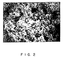
- Particulate B is silver agglomerate having a Fisher sub-sieve size (FSSS) of 0.6 micrometers, a tap density (by Tap-Pak Volumeter) of 1.85 g/cm 3 , a Scott apparent density of 1.02 g/cm 3 (16.7 g/in 3 ), a surface area of 1.62m 2 /g and a size distribution of 100% ⁇ 10.6 micrometers, 90% ⁇ 8.10 micrometers, 50% ⁇ 4.4 micrometers, and 10% ⁇ 1.40 micrometers with a mean size of 4.5 micrometers.
- a suitable particulate B is "Silver Powder SPS-100" available from Metz Metallurgical Corporation. This silver agglomerate as shown in the photomicrograph of FIG. 2, has many rough surface features.
- Particulate C is silver powder having a Fisher Sub-Sieve Size (FSSS) of 0.70 microns, a tap density (by Tap-Pak Volumeter) of 2.75 g/cm 3 , a Scott apparent density of 1.07 g/cm 3 (17.5 g/in 3 ), and a surface area of 1.84m 2 /g and a size distribution of 100% ⁇ 5.27 micrometer, 90% ⁇ 3.16 micrometer, 50% ⁇ 1.25 micrometer, and 10% ⁇ 0.51 micrometer.
- FSSS Fisher Sub-Sieve Size
- a suitable particulate C is "Fine Silver Powder S-ED" available from Metz Metallurgical Corporation.
- Particulates A, B, and C are mixed in a weight ratio of about 40%, 30%, and 30% to constitute the metallic silver filler that is admixed with the carrier.
- the carrier comprises a polymer mixture of two epoxy resins, Epoxy A and Epoxy B.
- Epoxy A is a bisphenol F epoxy resin such as "Aratronic 5046", a bisphenol F diglycidyl ether, having a relatively low viscosity of 1400 cps at 25°C, available from the Ciba-Geigy Corporation.
- Epoxy B is a liquid phenol epoxy novolac resin, such as "Quatrex 2010", a phenol epoxy novolac resin having a relatively high viscosity of 25,000-45,000 cps at 52°C, available from Dow Chemical Corporation, Midland, MI.
- the polymeric carrier may also include a conventional hardener such as an imidazole, for instance, N-(2-cyanoethyl)-2-ethyl,4-methylimidazole, available from PolyOrganix Corporation of Newburyport, MA under the CURIMIDTM-CN designation.
- a conventional hardener such as an imidazole, for instance, N-(2-cyanoethyl)-2-ethyl,4-methylimidazole, available from PolyOrganix Corporation of Newburyport, MA under the CURIMIDTM-CN designation.
- the polymeric carrier can also include a coupling or wetting agent to provide enhanced wetting of the uncured material.
- a representative coupling agent is gamma-glycidoxypropyltrimethoxysilane, available from the Union Carbide Company under the "A-187" designation.
- Yet another adjuvant includable in the polymeric carrier of the present invention is gamma-butyrolactone, available from the Aldrich Chemical Co., Milwaukee, WI, which material functions as a diluent to adjust viscosity.
- the 76.5% silver content represents a preferred value for common application techniques such as application by stencil, screen print, tampo print, syringe, etc.
- this conductive cement composition can exhibit electrical instability with resistance increasing by an order of magnitude under various test conditions. Above 78% this conductive cement composition is too viscous for use in stencil and screen printing applications, although still suitable for application by syringe.
- the above polymeric carrier was determined to have a volumetric shrinkage 17%.
- electrical leads were initially cleaned with acetone and the above formulation used to connect a 68-pin surface-mount device (SMD), a 44-pin surface-mount device, and a series-connected resistor string in each of six test circuits (Trials 1-6) as described in Example I.
- SMD 68-pin surface-mount device
- 44-pin surface-mount device 44-pin surface-mount device
- Trials 1-6 series-connected resistor string in each of six test circuits as described in Example I.
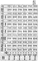
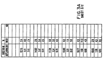
- junction resistance was measured at room temperature and at test conditions of 60°C and 90% relative humidity as shown in FIG. 3A.
- the resistivity was then again measured after 17, 40, 112, 306, 618, and 1002 hours exposure at the 60°C and 90% relative humidity test conditions.
- the ohmic resistance of all junctions varied minimally after 1002 hours at 90% relative humidity with only one set of junctions having an increase in resistance over 11%.
- the electrical leads of the above-described devices were first cleaned with an inorganic acid and the connections made with the formulation of this Example in the manner described above.
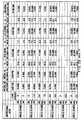
- the junction resistance was measured at room temperature and at test conditions of 60°C and 90% relative humidity as shown in FIG. 3B.
- the resistivity was then measured after 14.5, 117.5, 149, 297, and 969 hours exposure at the 60°C and 90% relative humidity test conditions.
- the ohmic resistance of all junctions varied minimally after 969 hours at 90% relative humidity with only one set of junctions having an increase in resistance over 12%.
- a conductive cement is prepared using a conductive particle filler of three types of silver particulates A,B, and C.
- Particulates A, B, and C are those described above in Example II and are similarly mixed in a weight ratio of 40%, 30%, and 30% to constitute a filler that is admixed with a carrier.
- the carrier comprises a single epoxy resin.
- the epoxy is a liquid bisphenol A epoxy resin such as "Quantrex 1010", having a viscosity of 11,000-14,000 cps at 25°C, available from the Dow Chemical Corporation.
- the polymeric carrier can also include a hardener (N-(2-cyanoethyl)-2-ethy1,4-methylimidazole), gamma-glycidoxypropyltrimethoxysilane and a diluent gamma-butyrolactone.
- a hardener N-(2-cyanoethyl)-2-ethy1,4-methylimidazole
- gamma-glycidoxypropyltrimethoxysilane and a diluent gamma-butyrolactone.
- the above polymeric carrier was determined to have a volumetric shrinkage of 13% and was used to connect a 68-pin surface-mount device (SMD), a 44-pin surface-mount device, and a series-connected resistor string in each of two test circuits (Trials 1-2) as described in Example I.
- the junction resistance was measured at room temperature and at test conditions of 60°C and 90% relative humidity as shown in FIG. 4.
- the resistivity was then again measured after 15, 65, and 141 hours exposure at the 60°C and 90% relative humidity test conditions.
- the ohmic resistance of all junctions varied minimally after 141 hours at 90% relative humidity with two (2) sets of junctions having an increase in resistance over 2%.
- a conductive cement is prepared using a conductive particle filler of two types of silver particulates A and C which are identical to particulates A and C described above for Example II.
- Particulates A and C are desirably mixed in a weight ratio of 40% and 60% to constitute the filler that is admixed with the carrier.
- the carrier comprises a mixture of two epoxy resins, Epoxy A and Epoxy B.
- Epoxy A is a bisphenol F epoxy resin such as "Aratronic 5046”.
- Epoxy B is a liquid phenol epoxy novolac resin, such as "Quatrex 2010”.
- the polymeric carrier can also include a hardener (N-(2-cyanoethyl)-2-ethy1,4-methylimidazole) a coupling agent (gamma-glycidoxypropyltrimethoxysilane) and a diluent (gamma-butyrolactone).
- a hardener N-(2-cyanoethyl)-2-ethy1,4-methylimidazole
- a coupling agent gamma-glycidoxypropyltrimethoxysilane
- a diluent gamma-butyrolactone
- the above polymeric carrier was determined to have a volumetric shrinkage of 10% and was used to connect a 68-pin surface-mount device (SMD), a 44-pin surface-mount device, and a series-connected resistor string in each of six test circuits (Trials 1-6) as described in Example I.
- the junction resistance was measured at room temperature and at test conditions of 60°C and 90% relative humidity as shown in FIG. 5.
- the resistivity was then again measured after 62, 136, 1073, and 1598 hours exposure at the 60°C and 90% relative humidity test conditions.
- the ohmic resistance of all junctions varied minimally after 1598 hours at 90% relative humidity with only one set of junctions having an increase in resistance over 19%.
- a conductive cement is prepared using a conductive filler of three types of silver particulates A, B, and C which are identical to particulates A, B, and C described above for Example II.
- Particulates A, B, and C are desirably mixed in a weight ratio of 40%, 30%, and 30% to constitute the filler that is mixed with a carrier.
- the carrier comprises a single epoxy/solvent combination.
- the epoxy is a bisphenol A epoxy resin such as 'EPONOL (R) 53-BH-35', a high molecular weight epoxy available from the Shell Chemical Company, Houston, TX.
- the epoxy resin represents about 35% of the as-supplied material with the remainder comprising a solvent of about 75% methyl ethyl ketone (MEK) and 25% propylene glycol methylether (PGME).
- MEK methyl ethyl ketone
- PGME propylene glycol methylether
- the above polymeric carrier was determined to have a volumetric shrinkage of 65% and was used to connect a 68-pin surface-mount device (SMD), a 44-pin surface-mount device, and a series-connected resistor string in each of six test circuits (Trials 1-6) as descried in Example I.
- the junction resistance was measured at room temperature and at test conditions of 60°C and 90% relative humidity as shown in FIG. 6.
- the resistivity was then measured after 6, 13, 349, and 1530 hours exposure at the 60°C and 90% relative humidity test conditions.
- the ohmic resistance of all junctions varied minimally after 1530 hours at 90% relative humidity with only one set of junctions having an increase in resistance over 10%.
- a conductive cement is prepared using a conductive particle filler of three types of silver particulates A, B, and C which are identical to particulates A, B, and C described above for Example II.
- Particulates A, B, and C are desirably mixed in a weight ratio of 40%, 30%, and 30% to constitute a filler that is mixed with a carrier.
- the carrier comprises a single epoxy/solvent combination.
- the epoxy is a novolac epoxy resin such as "Quatrex 2010", a phenol epoxy novolac resin having a relatively high viscosity of 25,000-45,000 cps at 52°C available from Dow Chemical Corporation.
- the solvent 2-(2-ethoxyethoxy) ethyl acetate is available under the tradename "Carbitol” acetate from the Eastman Kodak Co., Rochester, NY and is also known as diethylene glycol monoethyl ether acetate.
- the polymeric carrier can also include a hardener (N-(2-cyanoethyl)-2-ethy1,4-methylimidazole) and a coupling agent (gamma-glycidoxypropyltrimethoxysilane).
- a hardener N-(2-cyanoethyl)-2-ethy1,4-methylimidazole
- a coupling agent gamma-glycidoxypropyltrimethoxysilane
- the above polymeric carrier was determined to have a volumetric shrinkage of 25% and was used to connect a 68-pin surface-mount device (SMD), a 44-pin surface-mount device, and a series-connected resistor string in each of six test circuits (Trials 1-6) as described in Example I.
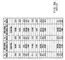
- the junction resistance was measured at room temperature and at test conditions of 60°C and 90% relative humidity as shown in FIG. 7.
- the resistivity was then again measured after 14, 62, and 1025 hours exposure at 60°C and 90% relative humidity test conditions. As shown by the % increment columns in FIG. 7, the ohmic resistance of all junctions varied minimally after 1025 hours at 90% relative humidity.
- a conductive cement is prepared using a conductive particle filler of three types of silver particulates A, B, and C which are identical to particulates A, B, and C described above for Example II.
- Particulates A, B, and C are desirably mixed in a weight ratio of 40%, 30%, and 30% to constitute the metallic silver filler that is admixed with a carrier.
- the carrier comprises a mixture of two epoxy resins, Epoxy A and Epoxy B.
- Epoxy A is a bisphenol A epoxy resin such as "Eponol 53" described above and Epoxy B is a liquid phenol Epoxy novolac resin, such as "Quatrex 1010", also described above.
- the polymeric carrier can also include hardeners I and II.
- Hardener I is a polyoxypropylenediamine available under the Jeffamine D-230 designation from the Texaco Chemical Company
- hardener II is a triethyleneglycoldiamine available under the Jeffamine EDR 148 designation, also from the Texaco Chemical Company.
- the polymeric carrier may include an accelerator to promote curing.
- a suitable accelerator such as a mixture of aliphatic amines is available from the Texaco Chemical Company under the '399' designation.
- the polymeric carrier may also include an adhesion promoter such as a glyceryl poly(oxypropylene) triamine available under the Jeffamine T-5000 designation from the Texaco Chemical Company.
- the above polymeric carrier was determined to have a volumetric shrinkage of 19% and was used to connect a 68-pin surface-mount device (SMD), a 44-pin surface-mount device, and a series-connected resistor string in each of six test circuits (Trials 1-6) as described in Example I.
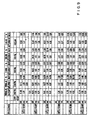
- the junction resistance was measured at room temperature and at test conditions of 60°C and 90% relative humidity as shown in FIG. 8.
- the resistivity was then again measured after 15, 191, and 981 hours exposure at the 60°C and 90% relative humidity test conditions.
- the ohmic resistance of all junctions varied minimally after 1598 hours at 90% relative humidity with only one set of junctions having an increase in resistance over 8%.
- a conductive cement is prepared using a conductive particle filler of two types of conductive particles, particulates A and D.
- Particulate A is identical to particulate A described above for Example I.
- Particulate D comprises silver-coated nickel particles having a mean particle dimension of 28u with an actual size distribution of 90% ⁇ 48.19 micrometers, 50% ⁇ 27.97 micrometers, and 10% ⁇ 12.36 micrometers.
- a suitable particulate D is available from Novamet Specialty Products Corp., an INCO Company, 681 Lawlins Road, Wyckof, N.J. 07481 (201-891-7976).
- Particulates A and D are desirably mixed in a weight ratio of 80% and 20% to constitute a filler that is admixed with a carrier.
- the carrier comprises a mixture of two epoxy resins, Epoxy A and Epoxy B.
- Epoxy A is a bisphenol F epoxy resin such as "Aratronic 5046"
- Epoxy B is a liquid phenol epoxy novolac resin, such as "Quatrex 2010”.
- the polymeric carrier can also include a hardener (N-(2-cyanoethyl)-2-ethy1,4-methylimidazole) and a coupling agent (gamma-glycidoxypropyltrimethoxysilane).
- a hardener N-(2-cyanoethyl)-2-ethy1,4-methylimidazole
- a coupling agent gamma-glycidoxypropyltrimethoxysilane
- the above polymeric carrier formulation was determined to have a volumetric shrinkage of 7.6% and was used to connect a 68-pin surface-mount device (SMD), a 44-pin surface-mount device, and a series-connected resistor string in each of six test circuits (Trials 1-6) as described in Example I.
- the junction resistance was measured at room temperature and at test conditions of 60°C and 90% relative humidity as shown in FIG. 9.
- the resistivity was then again measured after 119, 503, and 1146 hours exposure at the 60°C and 90% relative humidity test conditions.
- the ohmic resistance of all junctions varied minimally after 1146 hours at 90% relative humidity with only one set of junctions having an increase in resistance over 15%.
- a conductive cement is prepared using a conductive particle filler of two types of conductive particles, particulates A and E, of which particulate A is identical to particulate A described above for Example I.
- Particulates E are silver-coated nickel particles of about 32 % wt. silver having a Scott apparent density of 0.22 g/cm 3 (3.66 g/in 3 ), a surface area of 0.22m 2 /g, a powder resistivity of 0.4 m ohm.cm, and a mean particle dimension of 21u with an actual size distribution of 90 % ⁇ 29.3 micrometer, 50% ⁇ 19.5 micrometer, and 10% ⁇ 13.9 micrometer.
- a suitable particulate E is available from Potter Industries, Inc., Carlstadt, NJ under the Conducto-0-Fil Silver Nickel designation.
- Particulates A and E are desirably mixed in a weight ratio of 80% and 20% to constitute a filler that is admixed with a carrier.
- the carrier comprises principally a mixture of two epoxy resins, Epoxy A and Epoxy B.
- Epoxy A is a bisphenol F epoxy resin such as "Aratronic 5046"
- Epoxy B is a liquid phenol epoxy novolac resin, such as "Quatrex 2010”.
- the polymeric carrier can also include a hardener (N-(2-cyanoethyl)-2-ethyl,4-methylimidazole) and a coupling agent (gamma-glycidoxypropyltrimethoxysilane).
- a hardener N-(2-cyanoethyl)-2-ethyl,4-methylimidazole
- a coupling agent gamma-glycidoxypropyltrimethoxysilane
- the above polymeric carrier was determined to have a volumetric shrinkage characteristic of 7.6% and was used to connect a 68-pin surface-mount device (SMD), a 44-pin surface-mount device, and a series-connected resistor string in each of six test circuits (Trials 1-6) as described in Example I.
- the junction resistance was measured at room temperature and at test conditions of 60°C and 90% relative humidity as shown in FIG. 10.
- the resistivity was then again measured after 65, 453, 1096 hours exposure at the 60°C and 90% relative humidity test conditions.
- the ohmic resistance of all junctions varied minimally after 1096 hours at 90% relative humidity with only one set of junctions having an increase in resistance over 14%.
- a conductive cement is prepared using a conductive particle filler of two types of conductive particles, particulates A and F, of which particulate A is identical to particulate A described above for Example I.
- Particulates F are silver-coated glass spheres of about 23.8% silver having a Scott apparent density of 0.05 g/cm 3 (0.81 g/in 3 ), a powder resistivity of 2.63 milli-ohm cm, and a mean particle dimension of 13 micrometer with an actual size distribution of 90 % ⁇ 20.0 micrometer, 50% ⁇ 12.1 micrometer, and 10% ⁇ 7.1 micrometer.
- a suitable particulate F is available from Potter Industries, Inc., Carlstadt, NJ 07072 under the Conducto-0-Fil. Silvered Glass Spheres designation.
- Particulates A and F are desirably mixed in a weight ratio of 92% and 8% to constitute a filler that is admixed with a carrier.
- the carrier comprises principally a mixture of two epoxy resins, Epoxy A and Epoxy B.
- Epoxy A is a bisphenol F epoxy resin such as "Aratronic 5046"
- Epoxy B is a liquid phenol epoxy novolac resin, such as "Quatrex 2010”.
- the polymeric carrier can also include a conventional hardener (N-(2-cyanoethyl)-2-ethyl,4-methylimidazole) and a coupling agent (gamma-glycidoxypropyltrimethoxysilane).
- a conventional hardener N-(2-cyanoethyl)-2-ethyl,4-methylimidazole
- a coupling agent gamma-glycidoxypropyltrimethoxysilane
- the above polymeric carrier was determined to have a volumetric shrinkage characteristic of 7.6% and was used to connect a 68-pin surface-mount device (SMD), a 44-pin surface-mount device, and a series-connected resistor string in each of six test circuits (Trials 1-6) as described in Example I.
- the junction resistance was measured at room temperature and at test conditions of 60°C and 90% relative humidity as shown in FIG. 11.
- the resistivity was then again measured after 65, 453, and 1096 hours exposure at the 60°C and 90% relative humidity test conditions.
- the ohmic resistance of all junctions varied minimally after 1096 hours at 90% relative humidity with only two (2) sets of junctions having an increase in resistance over 15%.
- a conductive cement is prepared using a conductive particle filler including two types of silver particulates A and B.
- Particulates A and B are those described above in Example II and are similarly mixed in a weight ratio of 40% (A) to 60% (B) to constitute a filler that is admixed with a carrier.
- the carrier comprises a mixture of epoxy resins modified with a synthetic rubber.
- the modified epoxy mixture includes equal parts by weight of Bisphenol F epoxy resin such as "Aratronic 5046" a Bisphenol F diglycidyl ether, having a viscosity of about 1400 cps at 25°C available from the Ciba-Geigy Corporation; a liquid phenol epoxy novolac resin such as "Quatrex 2010", having a viscosity of about 25,000-45,000 cps at 52°C available from Dow Chemical Corporation; and a butadiene acrylonitrile synthetic rubber modifier such as "Heloxy WC-8005" having a viscosity of about 500,000-1,000,000 cps at 25°C available from Wilmington Chemical Corporation, Delaware, U.S.A.
- Bisphenol F epoxy resin such as "Aratronic 5046" a Bisphenol F diglycidyl ether, having a viscosity of about 1400 cps at 25°C available from the Ciba-G
- the polymeric carrier can also include an imidazole type hardener such as "Curimid-CN", N -(2-cyanoethyl) - 2-ethyl -4- methylimidazole; a diluent such as gamma-butrolactone; and a coupling agent such as "A-187", gamma-glicidoxypropyltrimethoxysilane.
- an imidazole type hardener such as "Curimid-CN", N -(2-cyanoethyl) - 2-ethyl -4- methylimidazole
- a diluent such as gamma-butrolactone
- a coupling agent such as "A-187", gamma-glicidoxypropyltrimethoxysilane.
- the above polymeric carrier was determined to have a volumetric shrinkage of 10%, a bending diameter of 1.27 cm (0.50 inch) (determined by bending a strip approximately 0.114 mm (4.5 mil) thick around the smallest diameter rod possible without damage or cracking of the strip) and was used to connect a 68-pin surface-mount device (SMD), a 44-pin surface-mount device and a series connected resistor string in each of three test circuits (trials 1-3) as described in Example I.
- SMD 68-pin surface-mount device
- 44-pin surface-mount device a 44-pin surface-mount device and a series connected resistor string in each of three test circuits (trials 1-3) as described in Example I.
- the junction resistance is measured at room temperature and at test conditions of 60°C and 90% relative humidity as shown in FIG. 12.
- the resistivity was again measured after 1031 hours exposure to 60°C at 90% relative humidity test conditions.
- the ohmic resistance of all junctions varied minimally or decreased after 1031 hours.
- a conductive cement is prepared using a conductive particle filler including two types of silver particulates A and B.
- Particulates A and B are those described above in Example II and are similarly mixed in a weight ratio of 40% (A) to 60% (B) to constitute a filler that is admixed with a carrier.
- the carrier comprises a non-filled urethane elastomer, such as "Calthane NF 1300", available from Cal Polymers, Inc., California, U.S.A., which comprises a mixture of about one part aromatic isocyanate ( 4,4-diphenylmethane diisocyanate and about 20% wt. higher molecular weight polymers) and three parts butadiene homopolymer (hyroxyl terminated polybutadiene).
- a non-filled urethane elastomer such as "Calthane NF 1300", available from Cal Polymers, Inc., California, U.S.A., which comprises a mixture of about one part aromatic isocyanate ( 4,4-diphenylmethane diisocyanate and about 20% wt. higher molecular weight polymers) and three parts butadiene homopolymer (hyroxyl terminated polybutadiene).
- the polymeric carrier can also include a small amount of solvent such as carbitol acetate ( 2-(2-ethoxyethoxy) ethyl acetate for adjusting viscosity.
- solvent such as carbitol acetate ( 2-(2-ethoxyethoxy) ethyl acetate for adjusting viscosity.
- the above polymeric carrier was determined to have a volumetric shrinkage of 7.7%, a bending diameter of 0.635 cm (0.25 inch) (determined by bending a strip approximately 0.114 mm (4.5 mil) thick around the smallest diameter rod possible without damage or cracking of the strip) and was used to connect a 68-pin surface-mount device (SMD), a 44-pin surface-mount device and a series connected resistor string in each of two test circuits (trials 1-2) as described in Example I.
- SMD 68-pin surface-mount device
- 44-pin surface-mount device a 44-pin surface-mount device and a series connected resistor string in each of two test circuits (trials 1-2) as described in Example I.
- the junction resistance was measured at room temperature and at test conditions of 60°C and 90% relative humidity as shown in FIG. 13.
- the resistivity was again measured after 429.5 hours exposure to 60°C at 90% relative humidity test conditions. As shown by the % increase column in FIG. 13, the ohmic resistance of all
- a conductive cement is prepared using a conductive particle filler including two types of silver particulates A and B.
- Particulates A and B are those described above in Example II and are similarly mixed in a weight ratio of 40% (A) to 60% (B) to constitute a filler that is admixed with a carrier.
- the carrier comprises a silicone resin, such as "SR 900", silicone conformal coating available from General Electric Company, Silicone Products Division, New York, U.S.A., which comprises a 50% solution of silicone resin, having a viscosity of about 500 cps at 25°C, in toluene solvent.
- silicone resin such as "SR 900”
- silicone conformal coating available from General Electric Company, Silicone Products Division, New York, U.S.A., which comprises a 50% solution of silicone resin, having a viscosity of about 500 cps at 25°C, in toluene solvent.
- the polymeric carrier can also include a small amount of additional solvent such as "Aromatic 150" which is a heavy aromatic solvent naphtha available from Exxon Chemical Co., Texas, U.S.A.
- the above polymeric carrier was determined to have a volumetric shrinkage of 25.0%, a bending diameter of 0.635 cm (0.25 inch) (determined by bending a strip approximately 0.114 mm (4.5 mil) thick around the smallest diameter rod possible without damage or cracking of the strip) and was used to connect a 68-pin surface-mount device (SMD) and a 44-pin surface-mount device in each of three test circuits (trials 1-3) as described in Example I. Similarly, a series connected resistor string was tested in two circuits (trials 1-2). The junction resistance was measured at room temperature and at test conditions of 60°C and 90% relative humidity as shown in FIG. 14. The resistivity was again measured after 192.5 hours exposure to 60°C at 90% relative humidity test conditions. As shown by the % increase column in FIG. 14, the ohmic resistance of all junctions varied minimally or decreased after 192.5 hours.
- the present invention advantageously provides an electrically conductive cement composition having substantially stable conductivity and resistance characteristics under high humidity conditions and is believed to achieve this result as a consequence of providing a cement having a volumetric shrinkage rate in a range that assures particle-to-particle contact and particle-to-connection surface contact to produce a reliable connection.
Claims (10)
- Elektrisch leitfähiger Zement zum Verkleben und Herstellen von feuchtigkeitsbeständigem elektrischem Kontakt zwischen zusammengeklebten Oberflächen, dera) einen schrumpffähigen klebenden Träger, der beim Härten mindestens 6,8% volumetrisch schrumpft und ausgewählt ist aus der Gruppe bestehend aus Epoxiharzen, die mit einem synthetischen Kautschuk modifiziert sind, Polyurethanharzen und Silikonharzen, und dispergiert in dem Trägerb) elektrisch-leitfähige Füllstoffteilchen umfaßt, von denen mindestens ein Teil in Kombination umfaßti) leitfähige Agglomerate, die eine rauhe Oberflächencharakteristik aufweisen, undii) Flockenteilchen, die eine Dicke von etwa einer Größenordnung kleiner als ihre Länge und Breite, eine FSSS von etwa 0,90 bis 1,30 µm, eine Klopfdichte von etwa 3,0 bis 3,5 g/cm3 eine Scottdichte von etwa 1,8 bis 2,1 g/cm3 (30 bis 35 g/in3) und eine Oberfläche von etwa 0,3 bis 0,6 m2/g aufweisen.
- Zement nach Anspruch 1, bei dem der Träger ein härtbarer polymerer Träger ist, der etwa 7,5 bis 65%, vorzugsweise mindestens 10%, volumetrisch beim Härten schrumpft.
- Zement nach Anspruch 1 oder 2, der ferner leitfähige Pulverteilchen enthält, um den elektrischen Teilchenzu-Teilchen-Kontakt zu verbessern.
- Zement nach Anspruch 3, bei dem die leitfähigen Pulverteilchen eine FSSS von etwa 0,75 µm, eine Klopfdichte von etwa 2,70 g/cm3, eine Scottdichte von etwa 1,2 g/cm3 (20,1 g/in3) und einer Oberfläche von etwa 1,41 m2/g aufweisen.
- Zement nach einem der vorhergehenden Ansprüche, bei dem der polymere Träger ein oder mehrere Harze umfaßt, vorzugsweise ausgewählt aus(a) Bisphenol F Epoxiharz,(b) flüssigem Phenolepoxinovolackharz,(c) Bisphenol A Epoxiharz,(d) Mischungen von (a), (b) und (c).
- Zement nach einem der vorhergehenden Ansprüche, bei dem der Füllstoff in einer Menge im Bereich von 60 bis 90 Gew.-%, bezogen auf das kombinierte Gewicht von Träger und Füllstoff, vorhanden ist.
- Zement nach einem der vorhergehenden Ansprüche, bei dem der Füllstoff eine Mischung von etwa 40 Gew.-% der Flocken und etwa 60 Gew.-% der leitfähigen Agglomerate ist.
- Zement nach Anspruch 7, bei dem der Träger in einer Menge von 21 Gew.-% vorhanden ist und etwa 5 Gew.-% Bisphenol F, etwa 5 Gew.-% Novolackepoxiharz, etwa 5 Gew.-% Butadienkautschuk und etwa 5 Gew.-% Härter, Verdünndungsmittel und Kupplungsmittel, alle bezogen auf das Gesamtgewicht des Zements, enthält.
- Zement nach Anspruch 7, bei dem der Träger a) in einer Menge von etwa 17 Gew.-% vorhanden ist und überwiegend Polyurethanharz ist, oder b) in einer Menge von etwa 27 Gew.-% vorhanden ist und überwiegend eine Mischung aus Silikon und Toluol ist.
- Verwendung eines elektrisch-leitfähigen Zements gemäß einem der Ansprüche 1 bis 9 zur Herstellung einer feuchtigkeitsbeständigen elektrischen Verbindung, die die Schritte derAufbringung des elektrisch-leitfähigen Zements auf eine Oberfläche undSchrumpfung des Träger zur Bewirkung des feuchtigkeitsbeständigen elektrischen Kontakts umfaßt.
Priority Applications (1)
| Application Number | Priority Date | Filing Date | Title |
|---|---|---|---|
| EP02012317A EP1246206B1 (de) | 1989-11-14 | 1990-11-14 | Feuchtigkeitsbeständige elektrisch leitfähige Zemente und Methode zur Herstellung und Anwendung derselben |
Applications Claiming Priority (6)
| Application Number | Priority Date | Filing Date | Title |
|---|---|---|---|
| US436199 | 1989-11-14 | ||
| US07/436,199 US5180523A (en) | 1989-11-14 | 1989-11-14 | Electrically conductive cement containing agglomerate, flake and powder metal fillers |
| US07/533,682 US5183593A (en) | 1989-11-14 | 1990-06-04 | Electrically conductive cement |
| US533682 | 1990-06-04 | ||
| US60755490A | 1990-11-01 | 1990-11-01 | |
| US607554 | 1990-11-01 |
Related Child Applications (1)
| Application Number | Title | Priority Date | Filing Date |
|---|---|---|---|
| EP02012317A Division EP1246206B1 (de) | 1989-11-14 | 1990-11-14 | Feuchtigkeitsbeständige elektrisch leitfähige Zemente und Methode zur Herstellung und Anwendung derselben |
Publications (2)
| Publication Number | Publication Date |
|---|---|
| EP0428165A1 EP0428165A1 (de) | 1991-05-22 |
| EP0428165B1 true EP0428165B1 (de) | 2002-11-20 |
Family
ID=27411905
Family Applications (2)
| Application Number | Title | Priority Date | Filing Date |
|---|---|---|---|
| EP02012317A Expired - Lifetime EP1246206B1 (de) | 1989-11-14 | 1990-11-14 | Feuchtigkeitsbeständige elektrisch leitfähige Zemente und Methode zur Herstellung und Anwendung derselben |
| EP90121829A Expired - Lifetime EP0428165B1 (de) | 1989-11-14 | 1990-11-14 | Feuchtigkeitsbeständige elektrisch leitfähige Zemente und Methode zur Herstellung und Anwendung derselben |
Family Applications Before (1)
| Application Number | Title | Priority Date | Filing Date |
|---|---|---|---|
| EP02012317A Expired - Lifetime EP1246206B1 (de) | 1989-11-14 | 1990-11-14 | Feuchtigkeitsbeständige elektrisch leitfähige Zemente und Methode zur Herstellung und Anwendung derselben |
Country Status (7)
| Country | Link |
|---|---|
| EP (2) | EP1246206B1 (de) |
| AT (2) | ATE355594T1 (de) |
| AU (1) | AU7048091A (de) |
| CA (1) | CA2068657C (de) |
| DE (3) | DE69034020T2 (de) |
| GB (1) | GB2239244B (de) |
| WO (1) | WO1991007759A1 (de) |
Families Citing this family (13)
| Publication number | Priority date | Publication date | Assignee | Title |
|---|---|---|---|---|
| JPH07123179B2 (ja) * | 1990-10-05 | 1995-12-25 | 信越ポリマー株式会社 | 異方導電接着剤による回路基板の接続構造 |
| DE4122450A1 (de) * | 1991-06-12 | 1992-12-17 | Beiersdorf Ag | Reaktiver warmschmelzklebstoff |
| US5613862A (en) * | 1992-07-18 | 1997-03-25 | Central Research Laboratories Limited | Anisotropic electrical connection |
| GB2269059A (en) * | 1992-07-18 | 1994-01-26 | Central Research Lab Ltd | Insulation displacement anisotropic electrical connection. |
| DE4228608C2 (de) * | 1992-08-28 | 1994-12-22 | Fraunhofer Ges Forschung | Elektrisch leitender Kleber, Verfahren zu dessen Herstellung sowie dessen Verwendung |
| JP3689159B2 (ja) * | 1995-12-01 | 2005-08-31 | ナミックス株式会社 | 導電性接着剤およびそれを用いた回路 |
| US5908881A (en) * | 1996-11-29 | 1999-06-01 | Sumitomo Bakelite Company Limited | Heat-conductive paste |
| US5891367A (en) * | 1998-02-23 | 1999-04-06 | General Motors Corporation | Conductive epoxy adhesive |
| DE10000834A1 (de) * | 2000-01-12 | 2001-08-16 | Fraunhofer Ges Forschung | Verfahren zur Herstellung elektrisch leitender Verbindungen |
| GB2365816B (en) | 2000-08-09 | 2002-11-13 | Murata Manufacturing Co | Method of bonding conductive adhesive and electrode,and bonded structure |
| WO2005015573A1 (ja) | 2003-08-08 | 2005-02-17 | Sumitomo Electric Industries, Ltd | 導電性ペースト |
| DE102013009234B4 (de) | 2012-06-01 | 2019-10-02 | Technische Universität Dresden | Verfahren zur Herstellung elektrisch leitender Verbindungen zwischen Fügepartnern sowie eine Verwendung eines Polymers oder Polymergemischs |
| WO2017134282A1 (en) * | 2016-02-05 | 2017-08-10 | Technische Universität München | Joining of components by means of energetically activated reactive particles |
Family Cites Families (12)
| Publication number | Priority date | Publication date | Assignee | Title |
|---|---|---|---|---|
| DE1933383A1 (de) * | 1968-07-01 | 1970-01-15 | Chomerics Inc | Metallteilchen-enthaltende Kunststoffzubereitung und deren Verwendung |
| US3968056A (en) * | 1974-09-27 | 1976-07-06 | General Electric Company | Radiation curable inks |
| JPS57111034A (en) * | 1980-12-10 | 1982-07-10 | Hitachi Ltd | Semiconductor device and its manufacture |
| US4487811A (en) * | 1980-12-29 | 1984-12-11 | General Electric Company | Electrical conductor |
| JPS57185316A (en) * | 1981-05-11 | 1982-11-15 | Sumitomo Metal Mining Co Ltd | Electrically conductive resin paste |
| NL8204288A (nl) * | 1982-11-05 | 1984-06-01 | Gen Electric | Polymeermengsel, werkwijze voor het bereiden van het polymeermengsel, voorwerpen gevormd uit het polymeermengsel. |
| DE3443789A1 (de) * | 1983-12-02 | 1985-06-27 | Osaka Soda Co. Ltd., Osaka | Elektrische leitende klebstoffmasse |
| US4747968A (en) * | 1985-05-08 | 1988-05-31 | Sheldahl, Inc. | Low temperature cure having single component conductive adhesive |
| JPS6261336A (ja) * | 1985-09-11 | 1987-03-18 | Toshiba Chem Corp | 半導体素子 |
| US4880570A (en) * | 1986-03-31 | 1989-11-14 | Harris Corporation | Electroconductive adhesive |
| JPH0733476B2 (ja) * | 1986-12-26 | 1995-04-12 | 三井東圧化学株式会社 | 銀ペ−スト |
| US4859364A (en) * | 1988-05-25 | 1989-08-22 | E. I. Du Pont De Nemours And Company | Conductive paste composition |
-
1990
- 1990-11-13 GB GB9024669A patent/GB2239244B/en not_active Expired - Fee Related
- 1990-11-14 AT AT02012317T patent/ATE355594T1/de not_active IP Right Cessation
- 1990-11-14 EP EP02012317A patent/EP1246206B1/de not_active Expired - Lifetime
- 1990-11-14 EP EP90121829A patent/EP0428165B1/de not_active Expired - Lifetime
- 1990-11-14 DE DE69034020T patent/DE69034020T2/de not_active Expired - Fee Related
- 1990-11-14 AT AT90121829T patent/ATE228264T1/de not_active IP Right Cessation
- 1990-11-14 WO PCT/US1990/006659 patent/WO1991007759A1/en active Application Filing
- 1990-11-14 AU AU70480/91A patent/AU7048091A/en not_active Abandoned
- 1990-11-14 DE DE4036274A patent/DE4036274A1/de not_active Withdrawn
- 1990-11-14 CA CA002068657A patent/CA2068657C/en not_active Expired - Lifetime
- 1990-11-14 DE DE69034236T patent/DE69034236T2/de not_active Expired - Fee Related
Also Published As
| Publication number | Publication date |
|---|---|
| GB2239244B (en) | 1994-06-01 |
| ATE355594T1 (de) | 2006-03-15 |
| GB9024669D0 (en) | 1991-01-02 |
| WO1991007759A1 (en) | 1991-05-30 |
| DE69034236D1 (de) | 2007-04-12 |
| CA2068657A1 (en) | 1991-05-15 |
| GB2239244A (en) | 1991-06-26 |
| CA2068657C (en) | 1998-01-06 |
| DE69034020D1 (de) | 2003-01-02 |
| EP0428165A1 (de) | 1991-05-22 |
| ATE228264T1 (de) | 2002-12-15 |
| EP1246206A3 (de) | 2004-04-14 |
| EP1246206A2 (de) | 2002-10-02 |
| EP1246206B1 (de) | 2007-02-28 |
| DE4036274A1 (de) | 1991-06-06 |
| DE69034236T2 (de) | 2007-10-31 |
| AU7048091A (en) | 1991-06-13 |
| DE69034020T2 (de) | 2003-10-09 |
Similar Documents
| Publication | Publication Date | Title |
|---|---|---|
| US5183593A (en) | Electrically conductive cement | |
| US5326636A (en) | Assembly using electrically conductive cement | |
| EP0169060B1 (de) | Schweissbare leitfähige Zusammensetzungen, ihre Anwendung als Beschichtungen auf Substraten und geeignete Zusammensetzungen zu ihrer Bildung | |
| EP0428165B1 (de) | Feuchtigkeitsbeständige elektrisch leitfähige Zemente und Methode zur Herstellung und Anwendung derselben | |
| EP0169059B1 (de) | Biegsame, direkt schweissbare, leitfähige Zusammensetzungen, geeignete Zusammensetzungen zu ihrer Bildung und ihre Anwendung als Beschichtungen auf Substraten | |
| US4731282A (en) | Anisotropic-electroconductive adhesive film | |
| KR100844970B1 (ko) | 전자 장치 용도의 전기적 안정성을 가진 전도성 및 저항성재료 | |
| KR101278991B1 (ko) | 이방 도전성 접착제 | |
| EP2377903A1 (de) | Filmhaftmittel und anisotropes leitfähiges haftmittel | |
| IE56869B1 (en) | Electrical interconnection means | |
| KR20030046552A (ko) | 매립된 레지스터를 갖는 인쇄회로기판 및 이의 제조방법 | |
| US4595605A (en) | Solderable conductive compositions that are capable of being soldered by non silver-bearing solder and that can be bonded directly to substrates and which are flexible | |
| KR20010083236A (ko) | 접속재료 | |
| JPH06295616A (ja) | 半田付け可能な塗膜形成用導電性ペースト | |
| EP0501270A1 (de) | Elektronische Vorrichtung mit uniaxial leitfähiger Klebezusammensetzung | |
| JP4110589B2 (ja) | 回路用接続部材及び回路板の製造法 | |
| JPH0855514A (ja) | 導電性粒子およびこれを用いた異方導電接着剤 | |
| JP3513636B2 (ja) | 複合導電粉、導電ペースト、電気回路及び電気回路の製造法 | |
| JP2008308519A (ja) | 電極接続用接着剤 | |
| JPH07207239A (ja) | 耐湿性導電性セメント及びそれの製造、使用方法 | |
| KR101600446B1 (ko) | 전도성 고분자를 포함하는 도전성 접착제 및 접착필름 | |
| CN115038768A (zh) | 导电性胶粘剂、电磁波屏蔽膜以及导电性粘结膜 | |
| JPH07252460A (ja) | 接着剤 | |
| JP2001107020A (ja) | 導電性接着剤 | |
| JP2010174096A (ja) | 異方性導電接着剤 |
Legal Events
| Date | Code | Title | Description |
|---|---|---|---|
| PUAI | Public reference made under article 153(3) epc to a published international application that has entered the european phase |
Free format text: ORIGINAL CODE: 0009012 |
|
| 17P | Request for examination filed |
Effective date: 19901114 |
|
| AK | Designated contracting states |
Kind code of ref document: A1 Designated state(s): AT BE CH DE DK ES FR GB GR IT LI LU NL SE |
|
| 17Q | First examination report despatched |
Effective date: 19941216 |
|
| RAP1 | Party data changed (applicant data changed or rights of an application transferred) |
Owner name: POLY-FLEX CIRCUITS, INC. |
|
| RIN1 | Information on inventor provided before grant (corrected) |
Inventor name: DURAND, DAVID Inventor name: WEI, TAI SHING Inventor name: VIEAU, DAVID P. Inventor name: CHU, ANG-LING |
|
| GRAG | Despatch of communication of intention to grant |
Free format text: ORIGINAL CODE: EPIDOS AGRA |
|
| GRAG | Despatch of communication of intention to grant |
Free format text: ORIGINAL CODE: EPIDOS AGRA |
|
| GRAH | Despatch of communication of intention to grant a patent |
Free format text: ORIGINAL CODE: EPIDOS IGRA |
|
| GRAH | Despatch of communication of intention to grant a patent |
Free format text: ORIGINAL CODE: EPIDOS IGRA |
|
| GRAA | (expected) grant |
Free format text: ORIGINAL CODE: 0009210 |
|
| RBV | Designated contracting states (corrected) |
Designated state(s): AT BE CH DE DK ES FR GR IT LI LU NL SE |
|
| AK | Designated contracting states |
Kind code of ref document: B1 Designated state(s): AT BE CH DE DK ES FR GR IT LI LU NL SE |
|
| PG25 | Lapsed in a contracting state [announced via postgrant information from national office to epo] |
Ref country code: IT Free format text: LAPSE BECAUSE OF FAILURE TO SUBMIT A TRANSLATION OF THE DESCRIPTION OR TO PAY THE FEE WITHIN THE PRE;WARNING: LAPSES OF ITALIAN PATENTS WITH EFFECTIVE DATE BEFORE 2007 MAY HAVE OCCURRED AT ANY TIME BEFORE 2007. THE CORRECT EFFECTIVE DATE MAY BE DIFFERENT FROM THE ONE RECORDED.SCRIBED TIME-LIMIT Effective date: 20021120 Ref country code: AT Free format text: LAPSE BECAUSE OF FAILURE TO SUBMIT A TRANSLATION OF THE DESCRIPTION OR TO PAY THE FEE WITHIN THE PRESCRIBED TIME-LIMIT Effective date: 20021120 Ref country code: LI Free format text: LAPSE BECAUSE OF FAILURE TO SUBMIT A TRANSLATION OF THE DESCRIPTION OR TO PAY THE FEE WITHIN THE PRESCRIBED TIME-LIMIT Effective date: 20021120 Ref country code: CH Free format text: LAPSE BECAUSE OF FAILURE TO SUBMIT A TRANSLATION OF THE DESCRIPTION OR TO PAY THE FEE WITHIN THE PRESCRIBED TIME-LIMIT Effective date: 20021120 Ref country code: GR Free format text: LAPSE BECAUSE OF FAILURE TO SUBMIT A TRANSLATION OF THE DESCRIPTION OR TO PAY THE FEE WITHIN THE PRESCRIBED TIME-LIMIT Effective date: 20021120 Ref country code: BE Free format text: LAPSE BECAUSE OF FAILURE TO SUBMIT A TRANSLATION OF THE DESCRIPTION OR TO PAY THE FEE WITHIN THE PRESCRIBED TIME-LIMIT Effective date: 20021120 Ref country code: NL Free format text: LAPSE BECAUSE OF FAILURE TO SUBMIT A TRANSLATION OF THE DESCRIPTION OR TO PAY THE FEE WITHIN THE PRESCRIBED TIME-LIMIT Effective date: 20021120 |
|
| REF | Corresponds to: |
Ref document number: 228264 Country of ref document: AT Date of ref document: 20021215 Kind code of ref document: T |
|
| REG | Reference to a national code |
Ref country code: CH Ref legal event code: EP |
|
| REF | Corresponds to: |
Ref document number: 69034020 Country of ref document: DE Date of ref document: 20030102 |
|
| PG25 | Lapsed in a contracting state [announced via postgrant information from national office to epo] |
Ref country code: SE Free format text: LAPSE BECAUSE OF FAILURE TO SUBMIT A TRANSLATION OF THE DESCRIPTION OR TO PAY THE FEE WITHIN THE PRESCRIBED TIME-LIMIT Effective date: 20030220 Ref country code: DK Free format text: LAPSE BECAUSE OF FAILURE TO SUBMIT A TRANSLATION OF THE DESCRIPTION OR TO PAY THE FEE WITHIN THE PRESCRIBED TIME-LIMIT Effective date: 20030220 |
|
| NLV1 | Nl: lapsed or annulled due to failure to fulfill the requirements of art. 29p and 29m of the patents act | ||
| PG25 | Lapsed in a contracting state [announced via postgrant information from national office to epo] |
Ref country code: ES Free format text: LAPSE BECAUSE OF FAILURE TO SUBMIT A TRANSLATION OF THE DESCRIPTION OR TO PAY THE FEE WITHIN THE PRESCRIBED TIME-LIMIT Effective date: 20030529 |
|
| REG | Reference to a national code |
Ref country code: CH Ref legal event code: PL |
|
| ET | Fr: translation filed | ||
| PLBE | No opposition filed within time limit |
Free format text: ORIGINAL CODE: 0009261 |
|
| STAA | Information on the status of an ep patent application or granted ep patent |
Free format text: STATUS: NO OPPOSITION FILED WITHIN TIME LIMIT |
|
| 26N | No opposition filed |
Effective date: 20030821 |
|
| PG25 | Lapsed in a contracting state [announced via postgrant information from national office to epo] |
Ref country code: LU Free format text: LAPSE BECAUSE OF NON-PAYMENT OF DUE FEES Effective date: 20031114 |
|
| PGFP | Annual fee paid to national office [announced via postgrant information from national office to epo] |
Ref country code: DE Payment date: 20081127 Year of fee payment: 19 |
|
| PGFP | Annual fee paid to national office [announced via postgrant information from national office to epo] |
Ref country code: FR Payment date: 20081128 Year of fee payment: 19 |
|
| REG | Reference to a national code |
Ref country code: FR Ref legal event code: ST Effective date: 20100730 |
|
| PG25 | Lapsed in a contracting state [announced via postgrant information from national office to epo] |
Ref country code: FR Free format text: LAPSE BECAUSE OF NON-PAYMENT OF DUE FEES Effective date: 20091130 |
|
| PG25 | Lapsed in a contracting state [announced via postgrant information from national office to epo] |
Ref country code: DE Free format text: LAPSE BECAUSE OF NON-PAYMENT OF DUE FEES Effective date: 20100601 |