EP0427194A2 - Dispositif du type torche multiple et méthode pour engendrer un plasma utilisant un tel dispositif - Google Patents
Dispositif du type torche multiple et méthode pour engendrer un plasma utilisant un tel dispositif Download PDFInfo
- Publication number
- EP0427194A2 EP0427194A2 EP90121200A EP90121200A EP0427194A2 EP 0427194 A2 EP0427194 A2 EP 0427194A2 EP 90121200 A EP90121200 A EP 90121200A EP 90121200 A EP90121200 A EP 90121200A EP 0427194 A2 EP0427194 A2 EP 0427194A2
- Authority
- EP
- European Patent Office
- Prior art keywords
- torch
- auxiliary
- main
- casing
- gas
- Prior art date
- Legal status (The legal status is an assumption and is not a legal conclusion. Google has not performed a legal analysis and makes no representation as to the accuracy of the status listed.)
- Granted
Links
- 238000000034 method Methods 0.000 title claims description 5
- 239000012212 insulator Substances 0.000 claims abstract description 44
- 239000000919 ceramic Substances 0.000 claims description 6
- 239000003779 heat-resistant material Substances 0.000 claims description 2
- 239000007789 gas Substances 0.000 description 111
- 238000005507 spraying Methods 0.000 description 18
- 239000007921 spray Substances 0.000 description 17
- 239000000463 material Substances 0.000 description 15
- 239000000758 substrate Substances 0.000 description 12
- 239000011248 coating agent Substances 0.000 description 11
- 238000000576 coating method Methods 0.000 description 11
- 239000002245 particle Substances 0.000 description 10
- XKRFYHLGVUSROY-UHFFFAOYSA-N Argon Chemical compound [Ar] XKRFYHLGVUSROY-UHFFFAOYSA-N 0.000 description 8
- 229910003460 diamond Inorganic materials 0.000 description 7
- 239000010432 diamond Substances 0.000 description 7
- 238000000926 separation method Methods 0.000 description 6
- 229910052786 argon Inorganic materials 0.000 description 4
- 230000015572 biosynthetic process Effects 0.000 description 4
- 230000000694 effects Effects 0.000 description 4
- 239000011261 inert gas Substances 0.000 description 4
- 238000004519 manufacturing process Methods 0.000 description 4
- 239000000126 substance Substances 0.000 description 4
- 238000012423 maintenance Methods 0.000 description 3
- 229910052751 metal Inorganic materials 0.000 description 3
- 239000002184 metal Substances 0.000 description 3
- 238000003892 spreading Methods 0.000 description 3
- 238000007751 thermal spraying Methods 0.000 description 3
- GWEVSGVZZGPLCZ-UHFFFAOYSA-N Titan oxide Chemical compound O=[Ti]=O GWEVSGVZZGPLCZ-UHFFFAOYSA-N 0.000 description 2
- QVGXLLKOCUKJST-UHFFFAOYSA-N atomic oxygen Chemical compound [O] QVGXLLKOCUKJST-UHFFFAOYSA-N 0.000 description 2
- 238000001816 cooling Methods 0.000 description 2
- 238000005520 cutting process Methods 0.000 description 2
- 239000001257 hydrogen Substances 0.000 description 2
- 229910052739 hydrogen Inorganic materials 0.000 description 2
- VNWKTOKETHGBQD-UHFFFAOYSA-N methane Chemical compound C VNWKTOKETHGBQD-UHFFFAOYSA-N 0.000 description 2
- 239000001301 oxygen Substances 0.000 description 2
- 229910052760 oxygen Inorganic materials 0.000 description 2
- 238000004381 surface treatment Methods 0.000 description 2
- UFHFLCQGNIYNRP-UHFFFAOYSA-N Hydrogen Chemical compound [H][H] UFHFLCQGNIYNRP-UHFFFAOYSA-N 0.000 description 1
- 206010037660 Pyrexia Diseases 0.000 description 1
- MCMNRKCIXSYSNV-UHFFFAOYSA-N ZrO2 Inorganic materials O=[Zr]=O MCMNRKCIXSYSNV-UHFFFAOYSA-N 0.000 description 1
- PNEYBMLMFCGWSK-UHFFFAOYSA-N aluminium oxide Inorganic materials [O-2].[O-2].[O-2].[Al+3].[Al+3] PNEYBMLMFCGWSK-UHFFFAOYSA-N 0.000 description 1
- 125000004429 atom Chemical group 0.000 description 1
- 239000002131 composite material Substances 0.000 description 1
- 239000000498 cooling water Substances 0.000 description 1
- 238000005516 engineering process Methods 0.000 description 1
- 239000010419 fine particle Substances 0.000 description 1
- 125000004435 hydrogen atom Chemical class [H]* 0.000 description 1
- 239000011810 insulating material Substances 0.000 description 1
- 150000002500 ions Chemical class 0.000 description 1
- 230000001590 oxidative effect Effects 0.000 description 1
- 238000007750 plasma spraying Methods 0.000 description 1
- 229920000136 polysorbate Polymers 0.000 description 1
- QHGVXILFMXYDRS-UHFFFAOYSA-N pyraclofos Chemical compound C1=C(OP(=O)(OCC)SCCC)C=NN1C1=CC=C(Cl)C=C1 QHGVXILFMXYDRS-UHFFFAOYSA-N 0.000 description 1
- 238000005245 sintering Methods 0.000 description 1
- UONOETXJSWQNOL-UHFFFAOYSA-N tungsten carbide Chemical compound [W+]#[C-] UONOETXJSWQNOL-UHFFFAOYSA-N 0.000 description 1
- XLYOFNOQVPJJNP-UHFFFAOYSA-N water Substances O XLYOFNOQVPJJNP-UHFFFAOYSA-N 0.000 description 1
- 229910001233 yttria-stabilized zirconia Inorganic materials 0.000 description 1
- RUDFQVOCFDJEEF-UHFFFAOYSA-N yttrium(III) oxide Inorganic materials [O-2].[O-2].[O-2].[Y+3].[Y+3] RUDFQVOCFDJEEF-UHFFFAOYSA-N 0.000 description 1
- 229910000859 α-Fe Inorganic materials 0.000 description 1
Images


Classifications
-
- B—PERFORMING OPERATIONS; TRANSPORTING
- B05—SPRAYING OR ATOMISING IN GENERAL; APPLYING FLUENT MATERIALS TO SURFACES, IN GENERAL
- B05B—SPRAYING APPARATUS; ATOMISING APPARATUS; NOZZLES
- B05B7/00—Spraying apparatus for discharge of liquids or other fluent materials from two or more sources, e.g. of liquid and air, of powder and gas
- B05B7/16—Spraying apparatus for discharge of liquids or other fluent materials from two or more sources, e.g. of liquid and air, of powder and gas incorporating means for heating or cooling the material to be sprayed
- B05B7/22—Spraying apparatus for discharge of liquids or other fluent materials from two or more sources, e.g. of liquid and air, of powder and gas incorporating means for heating or cooling the material to be sprayed electrically, magnetically or electromagnetically, e.g. by arc
- B05B7/222—Spraying apparatus for discharge of liquids or other fluent materials from two or more sources, e.g. of liquid and air, of powder and gas incorporating means for heating or cooling the material to be sprayed electrically, magnetically or electromagnetically, e.g. by arc using an arc
- B05B7/226—Spraying apparatus for discharge of liquids or other fluent materials from two or more sources, e.g. of liquid and air, of powder and gas incorporating means for heating or cooling the material to be sprayed electrically, magnetically or electromagnetically, e.g. by arc using an arc the material being originally a particulate material
-
- C—CHEMISTRY; METALLURGY
- C23—COATING METALLIC MATERIAL; COATING MATERIAL WITH METALLIC MATERIAL; CHEMICAL SURFACE TREATMENT; DIFFUSION TREATMENT OF METALLIC MATERIAL; COATING BY VACUUM EVAPORATION, BY SPUTTERING, BY ION IMPLANTATION OR BY CHEMICAL VAPOUR DEPOSITION, IN GENERAL; INHIBITING CORROSION OF METALLIC MATERIAL OR INCRUSTATION IN GENERAL
- C23C—COATING METALLIC MATERIAL; COATING MATERIAL WITH METALLIC MATERIAL; SURFACE TREATMENT OF METALLIC MATERIAL BY DIFFUSION INTO THE SURFACE, BY CHEMICAL CONVERSION OR SUBSTITUTION; COATING BY VACUUM EVAPORATION, BY SPUTTERING, BY ION IMPLANTATION OR BY CHEMICAL VAPOUR DEPOSITION, IN GENERAL
- C23C4/00—Coating by spraying the coating material in the molten state, e.g. by flame, plasma or electric discharge
- C23C4/12—Coating by spraying the coating material in the molten state, e.g. by flame, plasma or electric discharge characterised by the method of spraying
- C23C4/134—Plasma spraying
-
- H—ELECTRICITY
- H05—ELECTRIC TECHNIQUES NOT OTHERWISE PROVIDED FOR
- H05H—PLASMA TECHNIQUE; PRODUCTION OF ACCELERATED ELECTRICALLY-CHARGED PARTICLES OR OF NEUTRONS; PRODUCTION OR ACCELERATION OF NEUTRAL MOLECULAR OR ATOMIC BEAMS
- H05H1/00—Generating plasma; Handling plasma
- H05H1/24—Generating plasma
- H05H1/26—Plasma torches
- H05H1/32—Plasma torches using an arc
- H05H1/44—Plasma torches using an arc using more than one torch
Definitions
- the present invention relates to a multiple torch type plasma generation device used for a plasma splay coating apparatus, artificial diamond manufacturing apparatus, cutting, jointing of metal and ceramics, reformation and surface treatment of substances, and the like, and a method of generating plasma in these apparatuses. More specifical strictlyly, the present invention relates to an improved plasma generation technology used in a so-called plasma spray coating apparatus, and the like by which metal, ceramics and other substances are melted by, for example, a large current flowing in a gas, i.e., so-called arc, and plasma generated by the arc, and sprayed onto a target to be treated so that a rigid coating is formed thereon.
- a plasma spray coating apparatus and the like by which metal, ceramics and other substances are melted by, for example, a large current flowing in a gas, i.e., so-called arc, and plasma generated by the arc, and sprayed onto a target to be treated so that a rigid coating is formed thereon.
- Figure 9 shows main parts of a general purpose multiple torch type plasma spray coating device of prior art, wherein a main torch 1 is composed of a main cathode 3, an insulator 27 surrounding the main cathode 3, a main casing 4 having a discharge port, a main casing gas supply port 5, a second main casing 31, which surrounds the main casing 4, has a narrow port and is disposed coaxially with the main casing 4 through an insulator 29, and a main power supply 7 having a negative terminal connected to the main cathode 3 and a positive terminal connected to the main casing 4 and the second main casing 31 through switching means 8 and 34.
- a second main gas 33 to be used in the main torch 1 is supplied into the space defined between the main casing 4 and the second main casing 31 through a second gas supply port 32.
- an auxiliary torch 2 is composed of an auxiliary torch start electrode 9, a first auxiliary casing 10, which surrounds the auxiliary torch start electrode 9, has a discharge port, and is mounted coaxially with the first torch start electrode 9 through an insulator 28, a second auxiliary casing 36 mounted coaxially with the auxiliary casing 10 through an insulator 30, and an auxiliary power supply 13 having a positive terminal connected to the positive terminal of the main power supply 7 and the auxiliary casing 10 of the auxiliary torch 2 and a negative terminal connected to the auxiliary torch start electrode through a switch means 14.
- An auxiliary gas 12 is supplied from an auxiliary gas supply port 11 and a second auxiliary gas 28 is supplied from a second auxiliary gas supply port 37.
- the torches shown in Figure 9 are started by the following sequence.
- the switch 8 is turned on so that the main power supply 7 causes main start arc 15 to be formed between the main cathode 3 and the discharge port of the main casing 4, and thus a main plasma gas 6 is heated to enable conducting plasma to be discharged from the extreme end of the main casing 4 of the main torch 1 through the narrow port of the second main casing 31.
- the switch means 34 is turned on and then the switch means 8 is turned off, the main start arc 15 is extinguished by formed plasma, and at the same time the arc discharged from the extreme end of the main cathode 3 forms second main casing start arc 35, so that the main plasma gas 6 and the second main gas 33 are heated to enable a plasma flame 23 to be discharged to the outside of the main torch 1.
- the switch means 14 is turned on so that the auxiliary power supply 13 enables auxiliary start arc 16 to be formed between the auxiliary casing 10 and the auxiliary torch start electrode 9, and thus the auxiliary gas 12 is heated by the arc to form conductive plasma to be discharged from the discharge port of the auxiliary casing 10.
- the conductive plasma if further discharged to the outside of the auxiliary torch 2 through the narrow port at the extreme end of the second auxiliary casing 36.
- the conductive plasma discharge from the main torch 1 and the auxiliary torch 2 forms a conducting path, because these torches are disposed such that the axes thereof intersect each other.
- the switches 34 and 14 are turned off at this stage, the main power supply 7 forms steady hair pin arc 17 from the extreme end of the main cathode 3 toward the outer surface of the narrow port of the auxiliary casing 10.
- the plasma flame 23 substantially aligned with the axis of the main torch 1 is formed, as shown in Figure 9.
- the direction of the arc getting to the auxiliary casing 10 serving an anode of the steady hair pin arc 17 is substantially aligned with the axis of the auxiliary torch 2, but the arc is curved toward the direction in which the plasma flame 23 is discharge by being attracted thereby.
- the inner wall of the narrow portion of the second auxiliary casing 36 is partially damaged and a degree of the damage is increased as the plasma torch is operated for a longer time, and the plasma torch cannot be finally operated.
- each of the main casing 4, the second main casing 21, the auxiliary casing 10, and the second auxiliary casing 36 is arranged as a jacket, and thus the interior thereof is cooled by circulating water, and the like, but this arrangement is not shown in Figure 9. Further, the cooling systems are omitted in the following description.
- an object of the present invention is to solve the following problems.
- a first problem to be solved by the present invention is that since a multiple torch type plasma spray coating apparatus of prior art using laminar plasma cannot narrow down a plasma flame in a turbulent flow region, it cannot effect a thermal spraying in an extended and stable state and thus effects a thermal spraying using laminar plasma with a relatively low arc output of, e.g., 17 KW, with the result that a high quality sprayed coating cannot be ob tained when a thermal spray material such as tungsten carbide in need of hypersonic speed plasma and the like is used.
- a second problem is that when hair pin arc, which is one of the features of the multiple torch type plasma spray apparatus is formed, arc getting to an auxiliary torch is curved by being attracted to a plasma flame from a main torch, which greatly and partially damages mainly the downstream side of the discharge port inner wall of the auxiliary torch and prevents the torch from being stably operated for a long time at a high output.
- a third problem is that the multiple torch type plasma spray coating apparatus has two or more torches each having such a multiple structure that an insulator surrounding a cathode is coaxially disposed herewith, then a casing surrounding the insulator is disposed and so on, and thus as a number of these components are sequentially assembled, a diameter of the torch is increased and made larger as compared with an output of the torch, the components of the torch are difficult to be coaxially assembled, the manufacturing cost thereof is expensive, the torch needs a multiple maintenance and is not good in portability, because of the increased weight thereof. As a result, this type of the torch has a large problem when it is commercially used.
- the gist of the present invention as a first emi nent feature is that a gas supply means is provided to enables a strong circulating as flow to be formed around an arc column and the axis of the arc column to be aligned with the axis a torch, a circulating annular gas sheath is coaxially formed therewith, the length of all the narrow ports of the casings of a main torch casing an auxiliary torch are extended within the range in which the arc column does not pass through the sheath, a potential difference between the start point and the end point of arc, i.e., an arc voltage is increased, a power effectively used by the arc which is determined by the product of an arc current and the arc voltage is increased, a thermal load applied to the narrow port inner walls of all the main torch casing and the auxiliary torch casing is greatly reduced, and the arc current is increased, and thus a so-called pinch effect is accelerated due to the above arrangement, the arc is more
- a second eminent feature is that a heat insulating material such as ceramics, and the like is used as an insulator for a torch constituting the multiple torch and all the insulators and casings having the same diameter are coaxially disposed to thereby provide the torch with a compact and simple arrangement.
- FIG 1 is a first embodiment by which a multiple torch type plasma spray coating apparatus according to the present invention is implemented.
- a main cathode 3 is coaxially held by a main casing 4 having a discharge port and an insulator 27 having a vortex gas formation means 47.
- a main plasma gas 6 is first supplied from a main plasma gas inlet 5 into a gas annular chamber 48, and then further supplied in the direction shown by arrows 51 through a single vortex flow forming hole 49 or a plurality of vortex flow forming holes 49 defined at equal intervals so that the plasma gas 6 is circulated along the inner wall 50 of the insulator 27.
- the vortex flow forming hole 49 is defined in a tangential direction with respect to the axis of a torch 1.
- a main power supply 7 has a negative terminal connected to the main cathode 3 and a positive terminal connected to the main casing 4 through a switch means 8.
- the main torch 1 is composed of the above-mentioned components.
- an auxiliary start electrode 9 is disposed such that it intersects the axis of the main torch 1, i.e., the axis of the main cathode 3 and coaxially held by an auxiliary casing 10 surrounding the main cathode 3 and having a discharge port at the extreme end thereof and an insulator 28 having a vortex gas formation means 47 similar to that of the insulator 27 of the main torch 1.
- An auxiliary power supply 13 has a negative terminal connected to the auxiliary casing 10 through a switch means 14 and a positive terminal connected both the auxiliary torch start electrode 9 and the positive terminal of the main power supply 7.
- the plasma 18 Since the plasma 18 has a conducting property, it forms a conducting path from the extreme end of the main cathode 3 to the extreme end of the auxiliary start electrode 9 in this state.
- the switch means 8 and 14 are turned off after this state has been completed, a voltage from the main power supply 7 is imposed across the extreme end of the main cathode 3 and the extreme end of the auxiliary torch start electrode 9, which forms steady hair pin arc 17 directed from the extreme end of the main cathode 3 to the extreme end of the auxiliary torch start electrode 9.
- a plasma flame 23 having substantially the same axis as that of the main torch 1 can be formed, as shown in Figure 1.
- the thus generated steady hair pin arc 17 has the start and end points thereof securely fixed to the extreme ends of the main cathode 3 and the auxiliary torch start electrode 9, respectively, and since the extreme ends the hair pin arc 17 are protected by the inert as, the main plasma gas 6 to be supplied into the main torch 1 can be set to an any arbitrary amount ranging from an large flow amount to a small flow amount.
- a plasma separation means 22 located just in front of the substrate 25 separates only the plasma 18 from the plasma flame 23 containing the fused spray particles 21, and the fused spray particles 21 comes into collision with the substrate just after the separation to thereby form a coating 24.
- the provision of the means for supplying a gas, by which a strong vortex gas flow is formed around the arc column enables the axis of the arc column to be aligned with the axis of the torch and a vortex annular gas sheath to be coaxially formed, with the result that the plasma flame 23 is narrowed down in a turbulent flow region in which the prior art multiple torch type plasma spray coating apparatus forming a laminar plasma flame cannot narrow down the plasma flame, and thus a spray coating can be effected in an extended and stable state at a high density, a thermal spray material is well melted and sprayed to the substrate at a high speed to thereby provide a high quality coating at an increased efficiency.
- FIG. 3 shows main parts of a general purpose multiple torch type plasma spray coating apparatus, wherein a main torch 1 is composed of an insulator 27 having a main gas inlet, a main casing 4 having a discharge port, an insulator 29 having a second main gas inlet 32, a second main casing 31 having a narrow port each coaxially disposed in alignment with the axis of a main cathode 1, the insulators 27 and 29 and the casings 4 and 31 having the same diameter, and a main power supply 7 having a negative terminal connected to the main cathode 3 and a positive terminal connected to the main casing 4 and the second main casing 31 through switch means 8 and 34, respectively.
- a main torch 1 is composed of an insulator 27 having a main gas inlet, a main casing 4 having a discharge port, an insulator 29 having a second main gas inlet 32, a second main casing 31 having a narrow port each coaxially disposed in alignment with the axis of
- a main plasma gas 6 or a second main gas 33 is first supplied into an gas annular chamber 48 from the main gas inlet 5 or the second main gas inlet 32, and then further supplied in the direction shown by arrows 51 through a single vortex flow forming hole 49 or a plurality of vortex flow forming holes 49 defined at equal intervals so that the plasma gas 6 is circulated along the inner wall 50 of the insulator 27 or 29.
- an auxiliary start electrode 9 is disposed such that it intersects the axis of the main torch 1, and coaxially held by an insulator 28, a first auxiliary casing 10 having a discharge port, an insulator 30 and a second auxiliary casing 36 coaxially disposed in this order, and further an auxiliary gas 12 is supplied from the auxiliary gas inlet 11 defined to the insulator 28 having a vortex gas formation means 47 similar to that of the insulator 27 or 29 of the main torch 1, and a second auxiliary gas 38 is supplied through the second auxiliary gas inlet 37 defined to the insulator 30.
- An auxiliary power supply 13 has a positive terminal connected to the positive terminal of the main power supply 7 and the auxiliary casing 10 of the auxiliary torch 2 and a negative terminal connected to the auxiliary torch start electrode 9 through a switch means 14.
- a second auxiliary torch 2 is composed of the above-mentioned components. The respective torches shown in Figure 3 are started by the following sequence.
- the switch means 8 is turned on to enable the main power supply 7 to first form main start arc 15 between the main cathode 3 and the discharge port of the main casing 4 to thereby heat the main plasma gas 6, and conducting plasma is discharged from the extreme end of the main casing 4 of the main torch 1 through the narrow port of the second main casing 31.
- the switch means 14 is turned on to enable the auxiliary power supply 13 to form auxiliary start arc 16 between the auxiliary casing 10 and the auxiliary torch start electrode 9
- the auxiliary gas 12 is heated by the arc, and the conducting plasma 18 discharged from the discharge port of the auxiliary casing 10 is further discharged to the outside of the auxiliary torch 2 through the narrow port at the extreme end of the second auxiliary casing 36.
- the conductive plasma 18 discharged from the extreme ends of the main torch 1 and the auxiliary torch 2 forms a conducting path, because the axis of the main torch 1 intersects the axis of the auxiliary torch 2.
- the main power supply 7 forms steady hair pin arc 17 directed from the extreme end of the main cathode 3 to the outer surface of the narrow port of the auxiliary casing 10.
- the plasma flame 23 having substantially the same axis as that of the main torch 1 is formed, as shown in Figure 3.
- the extreme end of the auxiliary torch start electrode 9 of the auxiliary torch 2 is caused to be located in the vicinity of the exit surface of the narrow port of the first auxiliary casing 10, as shown in Figure 6, although, in the prior art, the start electrode 9 of the auxiliary torch 2 is located in front of the narrow port of the first auxiliary casing 10 and the anode point thereof is located on the inner wall of the narrow port, as shown in Figure 9.
- the anode point of the auxiliary start arc 16 can be formed on the exit surface of the narrow port of the second auxiliary casing 36 and the auxiliary start arc 16 can be extended longer from the exit of the auxiliary torch 2 than that of the prior art shown in Figure 9, and thus the steady hair pin arc 17 can be easily formed.
- a plasma separation means 22 located just in front of the substrate 25 separates only the plasma 18 from the plasma flame 23 containing the fused spray particles 21, and the fused spray particles 21 comes into collision with the substrate just after the separation to thereby form a coating 24.
- the provision of the means for supplying a gas, by which a strong vortex gas flow is formed around the arc column enables the axis of the arc column to be aligned with the axis of the torch and a vortex annular gas sheath to be coaxially formed, with the result that the plasma flame 23 is narrowed down in a turbulent flow region in which the prior art multiple torch type plasma spray coating apparatus forming a laminar plasma flame cannot narrow down the plasma flame, and thus a spray coating can be effected in an extended and stable state at a high density, a thermal spray material is well melted and sprayed at a high speed to the substrate to thereby provide a high quality coating at an increased efficiency.
- an inert gas such as argon or the like as the main plasma gas
- an active gas such as air, oxygen, or the like can be used as the second main gas 33, or a composite gas can be used if it is needed for the other objects, and thus obtained is such an effective result that a field to which this torch can be applied is increased and an operating coat thereof is reduced.
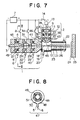
- FIG. 7 shows an embodiment preferably applied to the cases in which a large capacity is particularly needed and a ratio of an active gas contained in a plasma gas is to be increased.
- a main torch 1 of the embodiment is composed of an insulator 27 having a main gas inlet 5, a main casing 4 having a discharge port, an insulator 29 having a second main gas inlet 32, a main casing having a discharge port, an insulator 29 having a second main gas inlet 32, a second main casing 31 having a narrow port, an insulator 29 having a third main gas inlet 39, a third main casing 41 having a narrow port disposed in this order toward the extreme end of an main cathode 3 in alignment with the axis of thereof, the above components having the same diameter, and a main power supply 7 having a negative terminal connected to the main cathode 3 and a positive terminal connected to the main casing 4, the second main casing 31, and the third main casing 41 through switch means 8, 34 and 46, respectively.
- a main plasma gas 6, a second main gas 33, or a third main gas 40 is first supplied into an gas annular chamber 48 from the main gas inlet 5, the second main gas inlet 32, or the third main gas inlet 39, and then further supplied in the direction shown by arrows 51 through a single vortex flow forming hole 49 or a plurality of vortex flow forming holes 49 defined at equal intervals so that the plasma gas 6 is circulated along the inner wall 50 of the insulator 27 or 29.
- an auxiliary start electrode 9 is disposed such that it intersects the axis of the main torch 1, and an insulator 28 having an auxiliary gas inlet 11, a first auxiliary casing 10 having a discharge port, an insulator 30 having a second auxiliary gas inlet 37, a second auxiliary casing 36 having a narrow port, an insulator 30 having a third auxiliary gas inlet 42, and a third auxiliary casing 44 having a narrow port are coaxially disposed in this order toward the extreme end of the auxiliary torch start electrode 9 in alignment with the axis thereof.
- an auxiliary gas 12 is supplied from the auxiliary gas inlet 11 defined to the insulator 28 having a vortex gas formation means 47 similar to that of the insulator 27 or 29 of the main torch 1, a second auxiliary gas 38 is supplied from the second auxiliary gas inlet 37 defined to the insulator 30, an a third auxiliary gas 43 is supplied from the third auxiliary gas inlet 42 defined to the insulator 30.
- an auxiliary power supply 13 has a negative terminal connected to the auxiliary torch start electrode 9 and a positive terminal connected to the positive terminal of the main power supply 7 through a switch means 14 and also connected to the auxiliary casing 10.
- a second auxiliary torch 2 is composed of the above-mentioned components.
- the system shown in Figure 3 is started by the following sequence.
- the switch means 8 and 34 of the main torch 1 are sequentially turned on and off and only the switch means 46 is turned on to enable conductive plasma to be discharged from the extreme ends of the main torch 1 and the auxiliary torch 2. After the plasma has intersected each other and formed an conductive path between the cathodes of both the torches, the switch means 46 and 14 are turned off to form steady hair pin arc 17 to thereby generate plasma 18.
- a plasma coating according to the present invention is effected as shown in Figure 7 in the same way a shown in Figures 1 and 3.
- inert gas such as argon is used as the main plasma gas 6, the auxiliary gas 12, and the second auxiliary gas 38 to protect the electrode and the casings, but a reactive active gas such as air, oxygen or the like can be used as a plasma gas for the second main gas 33, the third main gas 40 and the third auxiliary gas 43.
- a ratio of the active gas contained in the plasma gas as a whole used in the torch can be increased, with the result that a coating composed of such a substance as ferrite, alumina, titania, or the like, which greatly dilikes a reducing atmosphere and can exhibit a unique high performance in an oxidizing atmosphere, can be easily formed, which is one of eminent features of the present invention.
- FIG. 5 shows and embodiment by which artificial diamond is made using the plasma generation device according to the present invention.
- the artificial diamond is made in such a manner that a material gas such as a material gas 20 composed of methane and hydrogen, which has been injected from a material supply tube 19 into a ultra-high temperature plasma flame 23 generated by the above-mentioned multiple torch type plasma generation apparatus composed of the main torch 1 and the auxiliary torch 2 of the above-mentioned embodiment, is melted and sprayed onto a substrate 53 cooled by a cooling water 52 to form a diamond film 54 on the surface thereof, and at the time an exhaust gas 56 is exhausted from the exhaust port 58 defined to a housing 57.
- the diamond also can be synthesized by supplying, for example, hydrogen to the main torch 1 and/or the auxiliary torch 2.
- tow or three auxiliary torches are disposed in a circumferential direction at equal intervals in such a manner that they surround the axis of the main torch and the axes of the auxiliary torches inter sect the axis of the main torch at the one point thereof.
- the gas supply means is provided to enable a strong vortex gas flow to be formed around the arc column to thereby enable the axis of the arc column to be aligned with the axis of the torch and the vortex annular gas sheath to be coaxially formed therewith, with the result that the length of all the narrow ports of the main torch casings and then auxiliary torch casings is extended in the range in which the arc column does not pass through the sheath so that a potential difference between the start point and the end point of arc, i.e., an arc voltage is increased, a power effectively used by the arc which is determined by the product of an arc current and the arc voltage in increased, and a thermal load applied to be narrow port inner walls of all the main torch casings and the auxiliary torch casings is greatly reduced.
- a cooling efficiency of the torch as a whole can be reduced to substantially 30 % from a conventional ratio of 50 %, whereby the arc current is increased and at the same time a pinch effect is accelerated, the arc is more converged, a plasma flame is narrowed down to a high density and extended, a spray coating can be effected at a high output, high temperature and high speed, a larger amount of a spray coating material can be supplied, and a film of high quality can be provided.
- a spray coating was effected using yttria stabilized zirconia (Y2O3 - ZrO2) having a particle size from 44 to 10 ⁇ m as the thermal spray material, an amount of a gas passing through a film made by the material could be securely reduced to one half or less that obtained by the prior art torch type plasma spray coating apparatus.
- Y2O3 - ZrO2 yttria stabilized zirconia
- the provision of the means for supplying a gas, by which a strong vortex gas flow is formed around the arc column getting to the auxiliary torch enables the axis of the arc column to be aligned with the axis of the auxiliary torch and a vortex annular gas sheath to be coaxially formed, so that a thermal load applied to the narrow port inner walls of all the auxiliary torches is equally reduced, the inner walls are not partially damaged by the arc, and the torch can be stably operated without the need for maintenance and check.
- the use of a vortex gas flow can reduce a total amount of gas used in all the auxiliary torches by about 50 % as compared with that used in the prior art multiple torch type plasma spray coating apparatus from the same arc output, and stable steady hair pin arc can be also formed.
- the insulator used in each torch constituting a multiple torch is composed of a heat resistant material such as ceramics and all the insulators and casings are coaxially disposed in series, so that the size of the torch can be reduced. More specifically, the cost of manufacturing the same type of a multiple torch type plasma spray coating apparatus is reduced by about 40 % as compared with that of the prior art, and the outer appearance thereof is improved.
- the present invention can be effectively applied to the processing of substances such as the cutting and jointing of metal and ceramics, the generation and sintering of fine particles, and a surface treatment and the like such as a surface improvement effected by using generated active ions, atoms and the like, making use of the feature of the present invention, in addition to the above applications.
- the present invention can be various kinds of gases as a plasma gas, it is applicable to a wide variety of fields.
Landscapes
- Physics & Mathematics (AREA)
- Engineering & Computer Science (AREA)
- Plasma & Fusion (AREA)
- Chemical & Material Sciences (AREA)
- Mechanical Engineering (AREA)
- Spectroscopy & Molecular Physics (AREA)
- Chemical Kinetics & Catalysis (AREA)
- Materials Engineering (AREA)
- Electromagnetism (AREA)
- Metallurgy (AREA)
- Organic Chemistry (AREA)
- Plasma Technology (AREA)
- Coating By Spraying Or Casting (AREA)
- Electron Sources, Ion Sources (AREA)
- Arc Welding In General (AREA)
- Nozzles (AREA)
- Chemical Vapour Deposition (AREA)
Applications Claiming Priority (2)
| Application Number | Priority Date | Filing Date | Title |
|---|---|---|---|
| JP1289160A JPH03150341A (ja) | 1989-11-07 | 1989-11-07 | 複合トーチ型プラズマ発生装置とその装置を用いたプラズマ発生方法 |
| JP289160/89 | 1989-11-07 |
Publications (3)
| Publication Number | Publication Date |
|---|---|
| EP0427194A2 true EP0427194A2 (fr) | 1991-05-15 |
| EP0427194A3 EP0427194A3 (en) | 1991-12-11 |
| EP0427194B1 EP0427194B1 (fr) | 1996-05-22 |
Family
ID=17739538
Family Applications (1)
| Application Number | Title | Priority Date | Filing Date |
|---|---|---|---|
| EP90121200A Expired - Lifetime EP0427194B1 (fr) | 1989-11-07 | 1990-11-06 | Dispositif du type torche multiple et méthode pour engendrer un plasma utilisant un tel dispositif |
Country Status (4)
| Country | Link |
|---|---|
| US (1) | US5243169A (fr) |
| EP (1) | EP0427194B1 (fr) |
| JP (1) | JPH03150341A (fr) |
| DE (1) | DE69027089D1 (fr) |
Cited By (6)
| Publication number | Priority date | Publication date | Assignee | Title |
|---|---|---|---|---|
| US5514848A (en) * | 1994-10-14 | 1996-05-07 | The University Of British Columbia | Plasma torch electrode structure |
| EP0931176A1 (fr) * | 1996-09-30 | 1999-07-28 | Celestech, Inc. | Systeme ameliore de depot au jet de plasma |
| FR2775156A1 (fr) * | 1998-02-16 | 1999-08-20 | Lasers Et Tech Avancees Bureau | Dispositif de generation et de projection de jets pulses de plasma pour traitement de surface |
| EP1096837A3 (fr) * | 1999-10-25 | 2004-02-04 | Matsushita Electric Works, Ltd. | Dispositif de traitement par plasma et procédé de génération de plasma utilisant ce dispositif |
| CN102230216A (zh) * | 2011-06-19 | 2011-11-02 | 中国科学院研究生院 | 单晶金刚石的层流等离子体的制备方法 |
| EP2979767A4 (fr) * | 2013-03-28 | 2016-12-07 | Chugoku Electric Power | Dispositif de pulvérisation plasmatique |
Families Citing this family (32)
| Publication number | Priority date | Publication date | Assignee | Title |
|---|---|---|---|---|
| US5560779A (en) * | 1993-07-12 | 1996-10-01 | Olin Corporation | Apparatus for synthesizing diamond films utilizing an arc plasma |
| US5573682A (en) * | 1995-04-20 | 1996-11-12 | Plasma Processes | Plasma spray nozzle with low overspray and collimated flow |
| US6091043A (en) * | 1999-03-19 | 2000-07-18 | Ford Global Technologies, Inc. | Depositing metal upon an article |
| US8764978B2 (en) | 2001-07-16 | 2014-07-01 | Foret Plasma Labs, Llc | System for treating a substance with wave energy from an electrical arc and a second source |
| US8981250B2 (en) | 2001-07-16 | 2015-03-17 | Foret Plasma Labs, Llc | Apparatus for treating a substance with wave energy from plasma and an electrical Arc |
| US7622693B2 (en) * | 2001-07-16 | 2009-11-24 | Foret Plasma Labs, Llc | Plasma whirl reactor apparatus and methods of use |
| US10188119B2 (en) | 2001-07-16 | 2019-01-29 | Foret Plasma Labs, Llc | Method for treating a substance with wave energy from plasma and an electrical arc |
| US7857972B2 (en) | 2003-09-05 | 2010-12-28 | Foret Plasma Labs, Llc | Apparatus for treating liquids with wave energy from an electrical arc |
| US20110104381A1 (en) * | 2004-01-15 | 2011-05-05 | Stefan Laure | Plasma Treatment of Large-Scale Components |
| WO2006002258A2 (fr) * | 2004-06-22 | 2006-01-05 | Vladimir Belashchenko | Appareil thermique de projection a grande vitesse |
| US7750265B2 (en) * | 2004-11-24 | 2010-07-06 | Vladimir Belashchenko | Multi-electrode plasma system and method for thermal spraying |
| WO2006108395A1 (fr) * | 2005-04-11 | 2006-10-19 | Dr. Laure Plasmatechnologie Gmbh | Dispositif et procede de revetement par jet de plasma |
| WO2008008104A2 (fr) | 2006-04-05 | 2008-01-17 | Foret Plasma Labs, Llc | Système, procédé et appareil de traitement des liquides avec les vagues d'énergie du plasma |
| EP2150971B1 (fr) | 2007-05-11 | 2018-11-28 | Umicore AG & Co. KG | Procede et appareil de production de nanoparticules ultra-petites et uniformes |
| US8575059B1 (en) | 2007-10-15 | 2013-11-05 | SDCmaterials, Inc. | Method and system for forming plug and play metal compound catalysts |
| JP5091801B2 (ja) * | 2008-08-18 | 2012-12-05 | 株式会社日本セラテック | 複合トーチ型プラズマ発生装置 |
| US8197909B2 (en) * | 2008-08-26 | 2012-06-12 | Ford Global Technologies, Llc | Plasma coatings and method of making the same |
| US9126191B2 (en) | 2009-12-15 | 2015-09-08 | SDCmaterials, Inc. | Advanced catalysts for automotive applications |
| US8803025B2 (en) * | 2009-12-15 | 2014-08-12 | SDCmaterials, Inc. | Non-plugging D.C. plasma gun |
| US8481117B2 (en) * | 2010-03-08 | 2013-07-09 | United Technologies Corporation | Method for applying a thermal barrier coating |
| US8362386B2 (en) * | 2010-06-09 | 2013-01-29 | General Electric Company | Power delivery unit, plasma spray system, and method of using plasma spray system |
| US8916795B2 (en) * | 2011-03-28 | 2014-12-23 | Lockheed Martin Corporation | Plasma actuated vortex generators |
| US9156025B2 (en) | 2012-11-21 | 2015-10-13 | SDCmaterials, Inc. | Three-way catalytic converter using nanoparticles |
| US9511352B2 (en) | 2012-11-21 | 2016-12-06 | SDCmaterials, Inc. | Three-way catalytic converter using nanoparticles |
| US9499443B2 (en) | 2012-12-11 | 2016-11-22 | Foret Plasma Labs, Llc | Apparatus and method for sintering proppants |
| EP2971488B1 (fr) | 2013-03-12 | 2018-09-26 | Foret Plasma Labs, Llc | Appareil et procédé de frittage d'agents de soutènement |
| US9586179B2 (en) | 2013-07-25 | 2017-03-07 | SDCmaterials, Inc. | Washcoats and coated substrates for catalytic converters and methods of making and using same |
| US9517448B2 (en) | 2013-10-22 | 2016-12-13 | SDCmaterials, Inc. | Compositions of lean NOx trap (LNT) systems and methods of making and using same |
| CA2926133A1 (fr) | 2013-10-22 | 2015-04-30 | SDCmaterials, Inc. | Conception de catalyseurs pour moteurs a combustion diesel de grande puissance |
| EP3119500A4 (fr) | 2014-03-21 | 2017-12-13 | SDC Materials, Inc. | Compositions pour systèmes d'adsorption de nox passive (pna) et leurs procédés de fabrication et d'utilisation |
| EP3760013A1 (fr) * | 2018-02-27 | 2021-01-06 | Oerlikon Metco AG, Wohlen | Buse à plasma pour un pistolet de pulvérisation thermique et son procédé de fabrication et d'utilisation |
| KR102398023B1 (ko) * | 2021-08-24 | 2022-05-16 | 오경화 | 고밀도 상압 플라즈마 발생장치 |
Citations (3)
| Publication number | Priority date | Publication date | Assignee | Title |
|---|---|---|---|---|
| US3770935A (en) * | 1970-12-25 | 1973-11-06 | Rikagaku Kenkyusho | Plasma jet generator |
| FR2450548A1 (fr) * | 1979-03-01 | 1980-09-26 | Rikagaku Kenkyusho | Procede de mise en oeuvre d'un generateur de plasma |
| EP0249238A2 (fr) * | 1986-06-13 | 1987-12-16 | The Perkin-Elmer Corporation | Torche à plasma munie d'une cathode réglable |
Family Cites Families (12)
| Publication number | Priority date | Publication date | Assignee | Title |
|---|---|---|---|---|
| JPS5210809B2 (fr) * | 1971-09-17 | 1977-03-26 | ||
| JPS5313144B2 (fr) * | 1972-07-20 | 1978-05-08 | ||
| JPS55117577A (en) * | 1979-03-01 | 1980-09-09 | Rikagaku Kenkyusho | Operating method of plasma generator |
| US4818837A (en) * | 1984-09-27 | 1989-04-04 | Regents Of The University Of Minnesota | Multiple arc plasma device with continuous gas jet |
| US4674683A (en) * | 1986-05-06 | 1987-06-23 | The Perkin-Elmer Corporation | Plasma flame spray gun method and apparatus with adjustable ratio of radial and tangential plasma gas flow |
| DE3619187A1 (de) * | 1986-06-06 | 1987-12-10 | Man Nutzfahrzeuge Gmbh | Kraftfahrzeug, insbesondere im stop-and-go-verkehr betriebenes nutzfahrzeug |
| JPS63239800A (ja) * | 1987-03-27 | 1988-10-05 | 日本電子株式会社 | 誘導プラズマト−チ構造 |
| FR2614751B1 (fr) * | 1987-04-29 | 1991-10-04 | Aerospatiale | Procede et dispositif pour l'injection d'une matiere sous forme fluide dans un ecoulement gazeux chaud et appareil mettant en oeuvre ce procede |
| US4764656A (en) * | 1987-05-15 | 1988-08-16 | Browning James A | Transferred-arc plasma apparatus and process with gas heating in excess of anode heating at the workpiece |
| JPS6411074A (en) * | 1987-07-06 | 1989-01-13 | Komatsu Mfg Co Ltd | Plasma nozzle torch device |
| US4907407A (en) * | 1988-02-10 | 1990-03-13 | Olin Corporation | Lifetime arcjet thruster |
| US4982067A (en) * | 1988-11-04 | 1991-01-01 | Marantz Daniel Richard | Plasma generating apparatus and method |
-
1989
- 1989-11-07 JP JP1289160A patent/JPH03150341A/ja active Pending
-
1990
- 1990-11-06 EP EP90121200A patent/EP0427194B1/fr not_active Expired - Lifetime
- 1990-11-06 US US07/609,795 patent/US5243169A/en not_active Expired - Fee Related
- 1990-11-06 DE DE69027089T patent/DE69027089D1/de not_active Expired - Lifetime
Patent Citations (3)
| Publication number | Priority date | Publication date | Assignee | Title |
|---|---|---|---|---|
| US3770935A (en) * | 1970-12-25 | 1973-11-06 | Rikagaku Kenkyusho | Plasma jet generator |
| FR2450548A1 (fr) * | 1979-03-01 | 1980-09-26 | Rikagaku Kenkyusho | Procede de mise en oeuvre d'un generateur de plasma |
| EP0249238A2 (fr) * | 1986-06-13 | 1987-12-16 | The Perkin-Elmer Corporation | Torche à plasma munie d'une cathode réglable |
Cited By (8)
| Publication number | Priority date | Publication date | Assignee | Title |
|---|---|---|---|---|
| US5514848A (en) * | 1994-10-14 | 1996-05-07 | The University Of British Columbia | Plasma torch electrode structure |
| EP0931176A1 (fr) * | 1996-09-30 | 1999-07-28 | Celestech, Inc. | Systeme ameliore de depot au jet de plasma |
| EP0931176A4 (fr) * | 1996-09-30 | 2004-03-17 | Saint Gobain Norton Ind Cerami | Systeme ameliore de depot au jet de plasma |
| FR2775156A1 (fr) * | 1998-02-16 | 1999-08-20 | Lasers Et Tech Avancees Bureau | Dispositif de generation et de projection de jets pulses de plasma pour traitement de surface |
| EP1096837A3 (fr) * | 1999-10-25 | 2004-02-04 | Matsushita Electric Works, Ltd. | Dispositif de traitement par plasma et procédé de génération de plasma utilisant ce dispositif |
| CN102230216A (zh) * | 2011-06-19 | 2011-11-02 | 中国科学院研究生院 | 单晶金刚石的层流等离子体的制备方法 |
| EP2979767A4 (fr) * | 2013-03-28 | 2016-12-07 | Chugoku Electric Power | Dispositif de pulvérisation plasmatique |
| US9802212B2 (en) | 2013-03-28 | 2017-10-31 | The Chugoku Electric Power Co., Inc. | Plasma spraying apparatus |
Also Published As
| Publication number | Publication date |
|---|---|
| DE69027089D1 (de) | 1996-06-27 |
| EP0427194B1 (fr) | 1996-05-22 |
| EP0427194A3 (en) | 1991-12-11 |
| US5243169A (en) | 1993-09-07 |
| JPH03150341A (ja) | 1991-06-26 |
Similar Documents
| Publication | Publication Date | Title |
|---|---|---|
| EP0427194A2 (fr) | Dispositif du type torche multiple et méthode pour engendrer un plasma utilisant un tel dispositif | |
| CA1326886C (fr) | Methode et appareil de production de plasma | |
| EP1171900B1 (fr) | Jet de plasma grande surface a la pression atmospherique | |
| US5418430A (en) | Plasma generator with field-enhancing electrodes | |
| US5144110A (en) | Plasma spray gun and method of use | |
| JPS6213272A (ja) | ハイブリツド非トランスフアア−クプラズマト−チ及びその操作方法 | |
| US5374802A (en) | Vortex arc generator and method of controlling the length of the arc | |
| JPH0584454A (ja) | 粉末材料又は気体材料を溶射するためのプラズマ溶射装置 | |
| CA2498902C (fr) | Dispositif de pulverisation plasma | |
| JP2007506545A (ja) | パルス化アーク放電および適用される磁場を使用するナノ粉末合成 | |
| JP3733461B2 (ja) | 複合トーチ型プラズマ発生方法及び装置 | |
| JPH10189289A (ja) | 間接プラズマトロン | |
| WO2006012165A2 (fr) | Appareil destine a generer un jet de plasma ainsi que procede d'utilisation associe | |
| KR100760551B1 (ko) | 상압 플라즈마 발생장치 | |
| KR20030081060A (ko) | 뉴트럴라이저 형태의 고주파 전자 소스 | |
| US5095189A (en) | Method for reducing plasma constriction by intermediate injection of hydrogen in RF plasma gun | |
| US5296670A (en) | DC plasma arc generator with erosion control and method of operation | |
| US3472995A (en) | Electric arc torches | |
| Yugesh et al. | Influence of the shroud gas injection configuration on the characteristics of a DC non-transferred arc plasma torch | |
| JP5091801B2 (ja) | 複合トーチ型プラズマ発生装置 | |
| RU2092981C1 (ru) | Плазмотрон для напыления порошковых материалов | |
| JPH06290896A (ja) | 高周波プラズマヒータおよびその運転方法 | |
| JPS61116799A (ja) | 軸供給型大出力プラズマジエツト発生装置 | |
| JPH03173099A (ja) | 非冷却でプラズマジーンガスを導入するプラズマトーチ | |
| KR100493731B1 (ko) | 플라즈마 발생장치 |
Legal Events
| Date | Code | Title | Description |
|---|---|---|---|
| PUAI | Public reference made under article 153(3) epc to a published international application that has entered the european phase |
Free format text: ORIGINAL CODE: 0009012 |
|
| AK | Designated contracting states |
Kind code of ref document: A2 Designated state(s): DE FR GB |
|
| PUAL | Search report despatched |
Free format text: ORIGINAL CODE: 0009013 |
|
| AK | Designated contracting states |
Kind code of ref document: A3 Designated state(s): DE FR GB |
|
| 17P | Request for examination filed |
Effective date: 19920521 |
|
| 17Q | First examination report despatched |
Effective date: 19940520 |
|
| GRAH | Despatch of communication of intention to grant a patent |
Free format text: ORIGINAL CODE: EPIDOS IGRA |
|
| RAP1 | Party data changed (applicant data changed or rights of an application transferred) |
Owner name: CHICHIBU ONODA CEMENT CORPORATION |
|
| GRAA | (expected) grant |
Free format text: ORIGINAL CODE: 0009210 |
|
| AK | Designated contracting states |
Kind code of ref document: B1 Designated state(s): DE FR GB |
|
| PG25 | Lapsed in a contracting state [announced via postgrant information from national office to epo] |
Ref country code: FR Effective date: 19960522 |
|
| REF | Corresponds to: |
Ref document number: 69027089 Country of ref document: DE Date of ref document: 19960627 |
|
| PG25 | Lapsed in a contracting state [announced via postgrant information from national office to epo] |
Ref country code: DE Effective date: 19960823 |
|
| EN | Fr: translation not filed | ||
| EN | Fr: translation not filed | ||
| PG25 | Lapsed in a contracting state [announced via postgrant information from national office to epo] |
Ref country code: GB Effective date: 19961106 |
|
| PLBE | No opposition filed within time limit |
Free format text: ORIGINAL CODE: 0009261 |
|
| STAA | Information on the status of an ep patent application or granted ep patent |
Free format text: STATUS: NO OPPOSITION FILED WITHIN TIME LIMIT |
|
| 26N | No opposition filed | ||
| GBPC | Gb: european patent ceased through non-payment of renewal fee |
Effective date: 19961106 |