EP0426397B1 - Asymmetrischer Reflektor für LED - Google Patents
Asymmetrischer Reflektor für LED Download PDFInfo
- Publication number
- EP0426397B1 EP0426397B1 EP90311780A EP90311780A EP0426397B1 EP 0426397 B1 EP0426397 B1 EP 0426397B1 EP 90311780 A EP90311780 A EP 90311780A EP 90311780 A EP90311780 A EP 90311780A EP 0426397 B1 EP0426397 B1 EP 0426397B1
- Authority
- EP
- European Patent Office
- Prior art keywords
- section
- cup
- point
- lip
- edge point
- Prior art date
- Legal status (The legal status is an assumption and is not a legal conclusion. Google has not performed a legal analysis and makes no representation as to the accuracy of the status listed.)
- Expired - Lifetime
Links
Images
Classifications
-
- F—MECHANICAL ENGINEERING; LIGHTING; HEATING; WEAPONS; BLASTING
- F21—LIGHTING
- F21V—FUNCTIONAL FEATURES OR DETAILS OF LIGHTING DEVICES OR SYSTEMS THEREOF; STRUCTURAL COMBINATIONS OF LIGHTING DEVICES WITH OTHER ARTICLES, NOT OTHERWISE PROVIDED FOR
- F21V7/00—Reflectors for light sources
- F21V7/04—Optical design
- F21V7/09—Optical design with a combination of different curvatures
-
- F—MECHANICAL ENGINEERING; LIGHTING; HEATING; WEAPONS; BLASTING
- F21—LIGHTING
- F21K—NON-ELECTRIC LIGHT SOURCES USING LUMINESCENCE; LIGHT SOURCES USING ELECTROCHEMILUMINESCENCE; LIGHT SOURCES USING CHARGES OF COMBUSTIBLE MATERIAL; LIGHT SOURCES USING SEMICONDUCTOR DEVICES AS LIGHT-GENERATING ELEMENTS; LIGHT SOURCES NOT OTHERWISE PROVIDED FOR
- F21K9/00—Light sources using semiconductor devices as light-generating elements, e.g. using light-emitting diodes [LED] or lasers
- F21K9/60—Optical arrangements integrated in the light source, e.g. for improving the colour rendering index or the light extraction
- F21K9/69—Details of refractors forming part of the light source
-
- F—MECHANICAL ENGINEERING; LIGHTING; HEATING; WEAPONS; BLASTING
- F21—LIGHTING
- F21S—NON-PORTABLE LIGHTING DEVICES; SYSTEMS THEREOF; VEHICLE LIGHTING DEVICES SPECIALLY ADAPTED FOR VEHICLE EXTERIORS
- F21S43/00—Signalling devices specially adapted for vehicle exteriors, e.g. brake lamps, direction indicator lights or reversing lights
- F21S43/10—Signalling devices specially adapted for vehicle exteriors, e.g. brake lamps, direction indicator lights or reversing lights characterised by the light source
- F21S43/13—Signalling devices specially adapted for vehicle exteriors, e.g. brake lamps, direction indicator lights or reversing lights characterised by the light source characterised by the type of light source
- F21S43/14—Light emitting diodes [LED]
-
- F—MECHANICAL ENGINEERING; LIGHTING; HEATING; WEAPONS; BLASTING
- F21—LIGHTING
- F21S—NON-PORTABLE LIGHTING DEVICES; SYSTEMS THEREOF; VEHICLE LIGHTING DEVICES SPECIALLY ADAPTED FOR VEHICLE EXTERIORS
- F21S43/00—Signalling devices specially adapted for vehicle exteriors, e.g. brake lamps, direction indicator lights or reversing lights
- F21S43/10—Signalling devices specially adapted for vehicle exteriors, e.g. brake lamps, direction indicator lights or reversing lights characterised by the light source
- F21S43/13—Signalling devices specially adapted for vehicle exteriors, e.g. brake lamps, direction indicator lights or reversing lights characterised by the light source characterised by the type of light source
- F21S43/15—Strips of light sources
-
- F—MECHANICAL ENGINEERING; LIGHTING; HEATING; WEAPONS; BLASTING
- F21—LIGHTING
- F21S—NON-PORTABLE LIGHTING DEVICES; SYSTEMS THEREOF; VEHICLE LIGHTING DEVICES SPECIALLY ADAPTED FOR VEHICLE EXTERIORS
- F21S43/00—Signalling devices specially adapted for vehicle exteriors, e.g. brake lamps, direction indicator lights or reversing lights
- F21S43/20—Signalling devices specially adapted for vehicle exteriors, e.g. brake lamps, direction indicator lights or reversing lights characterised by refractors, transparent cover plates, light guides or filters
- F21S43/235—Light guides
- F21S43/251—Light guides the light guides being used to transmit light from remote light sources
-
- F—MECHANICAL ENGINEERING; LIGHTING; HEATING; WEAPONS; BLASTING
- F21—LIGHTING
- F21S—NON-PORTABLE LIGHTING DEVICES; SYSTEMS THEREOF; VEHICLE LIGHTING DEVICES SPECIALLY ADAPTED FOR VEHICLE EXTERIORS
- F21S43/00—Signalling devices specially adapted for vehicle exteriors, e.g. brake lamps, direction indicator lights or reversing lights
- F21S43/30—Signalling devices specially adapted for vehicle exteriors, e.g. brake lamps, direction indicator lights or reversing lights characterised by reflectors
-
- F—MECHANICAL ENGINEERING; LIGHTING; HEATING; WEAPONS; BLASTING
- F21—LIGHTING
- F21Y—INDEXING SCHEME ASSOCIATED WITH SUBCLASSES F21K, F21L, F21S and F21V, RELATING TO THE FORM OR THE KIND OF THE LIGHT SOURCES OR OF THE COLOUR OF THE LIGHT EMITTED
- F21Y2115/00—Light-generating elements of semiconductor light sources
- F21Y2115/10—Light-emitting diodes [LED]
-
- Y—GENERAL TAGGING OF NEW TECHNOLOGICAL DEVELOPMENTS; GENERAL TAGGING OF CROSS-SECTIONAL TECHNOLOGIES SPANNING OVER SEVERAL SECTIONS OF THE IPC; TECHNICAL SUBJECTS COVERED BY FORMER USPC CROSS-REFERENCE ART COLLECTIONS [XRACs] AND DIGESTS
- Y10—TECHNICAL SUBJECTS COVERED BY FORMER USPC
- Y10S—TECHNICAL SUBJECTS COVERED BY FORMER USPC CROSS-REFERENCE ART COLLECTIONS [XRACs] AND DIGESTS
- Y10S362/00—Illumination
- Y10S362/80—Light emitting diode
Definitions
- LEDs Light emitting diodes
- LEDs are becoming increasingly widely used in automobile design because of their longer lives and lower repair cost compared to the incandescent bulbs they replace.
- Present day automotive designers are specifying LEDs not only for indicator lamps and alphanumeric displays but also for high power illumination lamps such as center high mounted stop lights. LED stop lights require very high brightness, but only over a limited viewing angle.
- an LED stop light In order to be cost competitive with incandescent bulbs, an LED stop light must contain only a minimum number of individual LED lamps. The number of individual lamps can only be minimized if each lamp extracts substantially all of the light flux from the LED chip and concentrates the light within the useful viewing angle. Light flux outside of the viewing angle is wasted and might have been available to increase brightness within the viewing angle.
- the light source comprises a flux extractor cup for supporting a light source centered on an optical axis within a virtual positioning envelope and for directing light emitted by the source within a solid cup angle of the optical axis, the cup being rotationally symmetric about the optical axis and comprising in cross-section: a flat section located at the bottom of the cup and normal to the optical axis, for attachment of the light source, the flat section having a diameter equal to a diameter of the positioning envelope; a circular section extending from the flat section to a lower point located at an intersection with a projection of the cup angle through a nearest edge point of a top surface of the positioning envelope the circular section having a constant radius and a center at the nearest edge point; a lower parabolic section, extending from the lower point to an upper point located at an intersection with a projection of the top surface of
- the present invention provides a flux extractor cup for extracting light efficiently from a source positioned on an optical axis within an axially symmetrical virtual positioning envelope and for directing light emitted by the source within a flux path which is asymmetrical relative to the optical axis, the cup being asymmetrical with at least one high lip portion and one low lip portion; a flat section located at the bottom of the cup and normal to the optical axis, the flat section having a width equal to a diameter of the positioning envelope; and comprising in at least one side of a first longitudinal cross section: a circular section extending from the flat section to a lower point located at an intersection with a line from the opposite cup lip through a nearest edge point of a top surface of the positioning envelope, the circular section having a constant radius and a center at the nearest edge point; a lower parabolic section extending from the lower point to an upper point located at an intersection of the cup surface with a projection of the top surface of the positioning envelope, the lower parabolic section having a vertex at the
- the light source is an LED.
- the lamp produces a very bright output over a preselected limited viewing angle of cutoff angle which is asymmetrical relative to the axis of the lamp.
- the asymmetrical flux extraction cup may provide light to a second stage which further directs the light in a desired direction by itself, or in conjunction with an optional lens stage.
- the first stage of the lamp described herein is a flux extraction cup which supports the LED and concentrates its three dimension light flux into a desired flux path asymmetrical relative to the optical axis of the cup.
- the shape of each side of the cross section of the cup is determined by a combination of geometric features of the height of the cup lip on the opposite sides of the cup, and the edges of the envelope within which the LED is mounted in the bottom of the cup.
- Modern LED chips may be fabricated from GaAs, GaAsP, AlGaAs or other compounds and may use either absorbing or transparent substrates. Many of these chips are capable of emitting a Lambertian distribution of light flux from most, if not all, of the chip surfaces. To minimize input electrical power and to optimize efficiency, the lamp should extract and concentrate substantially all of the light flux rather than just that portion emitted by the LED top surface.
- An optimal LED illumination lamp would concentrate all of the light flux from the LED chip to create a maximum brightness within the desired viewing angle and zero brightness elsewhere. That area of illumination may not be symmetrical like the beam from an ordinary flashlight. It may be that it should be wider in a horizontal direction and narrower in a vertical direction, for example. It may be that the desired pattern of illumination is skewed to one side. That type of distribution may be achieved with a lamp with an asymmetrical reflector.
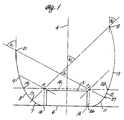
- FIG. 1 shows a longitudinal cross section of an LED illumination lamp 1 that is constructed in accordance with a preferred embodiment of the present invention using the principles of nonimaging optics.
- the drawing indicates only the longitudinal cross section of the inside surface of a reflector cup of an LED lamp.
- a reflector cup of an LED lamp Such a cup may be formed in the face of a metal body such as the end of a lead of the sort presently used in conventional LED lamps, or in a more or less flat surface having an array of LED lamps.
- Such a reflective cup may also be molded of plastic and have the inside surface metallized for high specular reflection.
- the construction of the cup is conventional and its internal shape as illustrated herein is novel.
- the lamp is effective to conserve brightness and to maximize intensity by cutting off the flux at a desired angle, A1 or A2, at the lip of the flux extraction cup and retaining the reflected light within those angles.
- An LED chip 3 sits within a flux extractor cup 5 which is fabricated within a conventional lead frame or the like.
- a bond wire (not shown) is connected to the top of the LED chip for providing current to the LED.
- the bottom of the LED chip (the body of the chip) is electrically connected to the cup by conductive epoxy adhesion to the interior surface of the cup. Such electrical connections are conventional.
- the size of such a flux extraction cup for an LED lamp is quite small.
- the LED chip may be a 400 micrometer square by 250 micrometer high AlGaAs red LED chip.
- the drawing in FIG. 1 extends through a diagonal of such an LED.
- the balance of the cup is drawn approximately to the same scale to give an idea of the small size of the cup.
- the cup includes four separate sections 6, 7, 8 and 9 on one side (the left side) of the cross section, and somewhat analogous four sections 6, 11, 12 and 13 on the opposite side (the right side) of the cross section.
- the flat bottom section 6 is present on both sides of the optical axis 4.
- the lip of the cup on the right side is higher above the bottom of the cup than the lip on the left side.
- the cutoff angle A1 of light from the cup is larger at the low side of the cup cross section than the cutoff angle A2 at the higher side of the cup.
- the LED chip 3 is attached to a flat bottom section 6 of the cup using an electrically conductive silver epoxy (not shown).
- the flat bottom section 6 is normal to the optical axis 4 and is slightly larger than the actual dimensions of the LED chip to allow for dimensional tolerances and slight manufacturing misalignment within an envelope 14.
- the projection of the envelope 14 onto the bottom of the cup may be circular even though the actual projection of the LED chip 3 is square.
- the envelope is cylindrical with a height equal to the nominal height or thickness of the LED chip plus its manufacturing and mounting tolerances, and a diameter equal to the diagonal of the LED chip plus the tolerances of the chip dimensions and placement of the chip in the bottom of the cup.
- a circular section 7 extends from a point 16 at the edge of flat bottom section 6 to a point 17.
- This point 17 is determined as the projection of the cup cutoff angle A2 from the higher lip 18 of the cup on the right side through the nearest top edge point F1 of the envelope 14.
- the surface 7 of cup forms a segment of a circle having a constant radius and a center at the nearest top edge point F1 of the envelope 14. That is, the surface intersects the plane of the cross section in a circular arc. Similar reference to the intersection of the surfaces with the cross sectional plane are made throughout the description and claims of this specification.
- a lower parabolic section 8 extends from the point 17 to a point 19.
- the point 19 is located on the inner surface of the cup at the same distance above the flat bottom section 6 as the top surface of the envelope 14.
- the lower parabolic section 8 is formed as a parabola having its vertex at point 17, its axis projecting through point 17, the near edge point F1 and the higher lip 18, and a focus at the near edge point F1 of the envelope.
- An upper parabolic section 9 extends from the point 19 to the lower lip 21 of the cup.
- the lower lip of the cup lies on the projection of the cup cutoff angle A1 from the low edge of the cup through the far edge point F2.
- the upper parabolic section 9 is formed as a parabola having an axis extending through the far edge point F2 of the envelope and parallel to the axis of the lower parabolic section 8. The focus of the upper parabolic section 9 is located at the far edge point F2.
- the shape of the lower parabolic section 8 is determined by reference to the cutoff angle A2 on the far side of the cup.
- the shape of the upper parabolic section 9 is determined by reference to an axis parallel to the axis of the lower parabolic section which is defined by the cut off angle A2.
- the shape of the lower parabola on the left side is a function of the right cutoff angle A2 and the shape of the upper parabola on the left side is a function of both cutoff angles.
- a circular section 11 extends from a point 26 at the edge of the flat bottom section 6 to a point 27. This point 27 is determined as the projection of the cup cutoff angle A1 from the lower lip 21 of the cup on the left side through the nearest top edge point F2 of the envelope 14. Between points 26 and 27, the surface 11 of cup forms a segment of a circle having a constant radius and a center at the nearest top edge point F2 of the envelope.
- a lower parabolic section 12 extends from the point 27 to a point 28.
- the point 28 is located on the inner surface of the cup at the same distance above the flat bottom section 6 as the top surface of the envelope 14,
- the lower parabolic section 12 is formed as a parabola having its vertex at point 27, its axis projecting through point 27, the near edge point F2 and the lower lip 21, and a focus at the near edge point F2 of the envelope.
- An upper parabolic section 13 extends from the point 28 to the higher lip 18 of the cup.
- the higher lip of the cup lies on the projection of the cup cutoff angle A2 from the high edge of the cup through the far edge point F1.
- the upper parabolic section 13 is formed as a parabola having an axis extending through the far edge point F1 of the envelope and parallel to the axis of the lower parabolic section 12. The focus of the upper parabolic section 13 is located at the far edge point F1.
- the longitudinal cross section may all be in a single plane where there is a higher lip on one edge of the cup and a lower lip on the opposite edge of the cup.
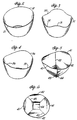
- a cup is illustrated semi-schematically in FIG. 2.
- the cup is illustrated as if it were a thin walled cup having an external shape the same as the internal shape. It will be apparent that this is solely for purposes of illustration and in a typical actual embodiment there would likely be very little relation between the internal and external shapes of such a cup.
- the shape of the interior surface of the cup may gradually change between the two cross-sectional shapes illustrated.
- the circular sections 7 and 11 adjacent to the flat base 6 in the bottom of the cup have the same radius all the way around the cup.
- the end of the circular section varies between the points 17 and 27.
- the intersection 19, 20 between the lower parabolic section and the upper parabolic section is at the same distance above the flat base all the way around the cup since it is a projection of the top of the positioning envelope 14.
- the shapes of the upper and lower parabolic sections gradually change between the shapes described and illustrated.
- Such a cup shape projects light within a skewed pattern having a relatively smaller cutoff angle A2 at the high side of the cup, a relatively larger cutoff angle A1 at the lower side of the cup and an intermediate cutoff angle therebetween.
- FIG. 3 illustrates another embodiment of cup for extracting and projecting a high proportion of flux from an LED or the like.
- a tulip-shaped cup having four relatively higher crests 31 and four intervening relatively lower valleys 32 around the lip of the cup.
- Such a non-axisymmetric cup with cutoff angles going through four cycles around the rim may be used for illuminating a more or less square area.
- the shape of a planar cross section through the cup may be symmetrical.
- a longitudinal cross section through opposite crests has circular and parabolic cross sections on opposite sides of the axis which are substantially the same.
- the planar cross section would also be symmetrical, but the shapes of the parabolic sections through opposite valleys would be different from the cross section through opposite crests.
- the shapes of the sections are determined by reference to the opposite and adjacent lips and edge points of the envelope as described above. In between the crests and valleys the shapes can gradually change.
- FIG. 4 illustrates another embodiment of cup which is not axisymmetric.
- this embodiment there are a pair of crests 36 on opposite sides of the lip of the cup.
- valleys 37 which are also 180° apart.
- Such an embodiment provides illumination in a somewhat oval pattern.
- the illuminated pattern is relatively wider in a horizontal direction and relatively narrower in a vertical direction.
- the same rules for determining the shape of the inside surface of the cup are used as hereinabove described.
- Cup shapes as provided in the embodiments of FIGS. 1 through 4 provide excellent flux extraction from the LED and projection within the illuminated area for rays lying in planes including the optical axis of the cup. There is Lambertian distribution of light emitted from the surfaces of the LED. Thus, there are rays which are not in the "axial" planes. There is good extraction and projection of such rays as well.
- a non-axisymmetric cup and non-symmetrical illumination pattern can afford to have less efficient total light flux extraction and projection. This may be the case, for example, where the cost of making the most efficient cup would be excessive for the application and a lower efficiency can be accepted to provide lower manufacturing costs.
- the costs of making the coining dies or injection casting molds for the tiny parts of such cup may be too high unless there is an appreciable volume of parts to be made. If that is the case a cup may be made with a geometry somewhat as illustrated in FIGS. 5 and 6.
- the lip of the cup has a pair of opposite crests 41 and a pair of opposite valleys 42 similar to the crests 36 and valleys 37 in the embodiment of FIG. 4.
- the shape of the interior surface of the cup in the axial planes through the crests and through the valleys are determined in the same general manner as hereinabove described. In between the crests and valleys there is a more abrupt transition between the shapes than in the gradual transitions mentioned above. Instead the shape of the cup is like that of two intersecting elongated troughs. One elongated trough extends perpendicular to the axial plane through the crests 41 at the lip of the cup. Throughout its length the elongated trough has the same shape as the shape in the axial plane.
- the shape of the axial cross section through the valleys 42 is determined as described above.
- the same cross section is provided along an elongated trough perpendicular to the axial plane through the valleys 42.
- the two elongated troughs intersect each other along lines 43 radiating from the corners of a square flat area 44 in the bottom of the cup.
- the upper edges of the intersecting elongated troughs are shaved to provide a more or less continuous lip between the crests and valleys 42.
- Such an embodiment may be manufactured from a die or stamp which is the complement of the inside of the cup.
- a die or stamp is made by cutting the complement of the elongated troughs in orthogonal directions.
- two additional intersecting elongated troughs may be employed midway between the principle elongated troughs having shapes determined by the crests 41 and valleys 42 at the lip of the cup.
- the shape of the desired secondary trough is determined by the same rules as described above for a lip height in between the higher and lower portions of the crests and valleys. This provides a shape intermediate between the shapes of the principal troughs.
- a die or stamp can then be made with orthogonal cuts of the complements of these secondary troughs 45° from the directions of the principal elongated troughs. This leaves an octagonal flat area in the bottom of the cup instead of the square area as illustrated in FIG. 6.
- the non-axisymmetric flux extraction cup has been described divorced from other optical elements. It will be apparent that light concentrating reflectors, lenses and the like may be provided adjacent to the mouth of the cup for concentrating or redirecting light projected from the cup.
- the flux extraction cup may be filled with a transparent epoxy or the like having a higher index of refraction than air. If so, and the transparent filling material has an interface with the air, suitable changes would be appropriate for determining the cup cutoff angles and projected lines for determining the shapes of the internal cup surface.
- the lip of the cup may not be a physical lip but only a geometrical lip for purposes of determining the optical properties of the reflective surfaces.
- the cup may have additional structure beyond the "lip" which does not affect the optical characteristics.
- the higher lip may be truncated for ease of manufacture of a cup.
- the amount of light emitted from the surfaces of the LED at angles greater than A2 which would be reflected from the portion of the higher wall surface above a transverse plane at the elevation of the lower lip 21 is rather small.
- the upper portion of the right wall above this plane could be omitted to make it easier to mold or stamp the cup without sacrificing a large amount of the efficiency.
- Most of the light would be within the cutoff angles A1 and A2 and such a compromise from the "ideal" design may be acceptable for practical considerations.
- the amount of light lost could be in the range of about 10%.
Landscapes
- Engineering & Computer Science (AREA)
- General Engineering & Computer Science (AREA)
- Physics & Mathematics (AREA)
- Microelectronics & Electronic Packaging (AREA)
- Optics & Photonics (AREA)
- Led Device Packages (AREA)
- Non-Portable Lighting Devices Or Systems Thereof (AREA)
Claims (9)
- Eine Lichtstromauswurfschale (5) zum effizienten Auswerfen von Licht aus einer Quelle (3), die auf einer optischen Achse (4) in einer achsensymmetrischen virtuellen Positionierungshülle positioniert ist, und zum Leiten des Lichts, das von der Quelle (3) emittiert wird, in einem Lichtstrompfad, der hinsichtlich der optischen Achse (4) asymmetrisch ist, wobei die Schale (5) mit mindestens einem hohen Lippenabschnitt (18) und einem niedrigen Lippenabschnitt (21) asymmetrisch ist;
wobei ein flacher Abschnitt (6) an der Grundfläche der Schale (5) angeordnet und senkrecht zu der optischen Achse (4) ist, wobei der flache Abschnitt eine Breite aufweist, die gleich dem Durchmesser der Positionierungshülle (14) ist;
und die auf zumindest einer Seite eines ersten longitudinalen Querschnitts folgende Merkmale aufweist:
einen kreisförmigen Abschnitt (7), der sich von dem flachen Abschnitt (6) zu einem unteren Punkt (17), der sich am Schnittpunkt zwischen einer Linie von der gegenüberliegenden Schalenlippe (18) durch einen nächstliegenden Kantenpunkt (F₁) einer oberen Oberfläche der Positionierungshülle (14) liegt, erstreckt, wobei der kreisförmige Abschnitt (7) einen konstanten Radius und den Mittelpunkt in dem nächstliegenden Kantenpunkt (F₁) hat;
einen unteren parabolischen Abschnitt (8), der sich von dem unteren Punkt (17) zu einem oberen Punkt (19), der im Schnittpunkt der Schalenoberfläche mit einer Projektion der oberen Oberfläche der Positionierungshülle (14) liegt, erstreckt, wobei der untere parabolische Abschnitt (8) den Scheitelpunkt im unteren Punkt (17), eine Achse, die sich durch den nächstliegenden Kantenpunkt (F₁) und den unteren Punkt (17) erstreckt, und den Brennpunkt im nächstliegenden Kantenpunkt (F₁) hat; und
einen oberen parabolischen Abschnitt (9), der sich von dem oberen Punkt (19) zu der näheren Schalenlippe (21) erstreckt, wobei der obere parabolische Abschnitt (9) den Scheitelpunkt auf der näheren Schalenlippe (21), eine Achse, die sich durch den entferntesten Kantenpunkt (F₂) und parallel zu der Achse des unteren parabolischen Abschnitts (8) erstreckt, und einen Brennpunkt, der im entferntesten Kantenpunkt (F₂) der oberen Oberfläche der Positionierungshülle liegt, hat;
und die auf mindestens einer Seite eines zweiten longitudinalen Querschnittes, der von dem ersten longitudinalen Querschnitt verschieden ist, folgende Merkmale aufweist:
einen kreisförmigen Abschnitt (11), der sich von dem flachen Abschnitt (6) zu einem unteren Punkt (27), der in einem Schnittpunkt mit einer Linie von der gegenüberliegenden Schalenlippe (21) durch einen nächstliegenden Kantenpunkt (F₂) der oberen Oberfläche der Positionierungshülle (14) liegt, erstreckt, wobei der kreisförmige Abschnitt (11) einen konstanten Radius und den Mittelpunkt in dem nächstliegenden Kantenpunkt (F₂) aufweist;
einen unteren parabolischen Abschnitt (12), der sich von dem unteren Punkt (27) zu einem oberen Punkt (28), der im Schnittpunkt der Schalenoberfläche mit einer Projektion der oberen Oberfläche der Positionierungshülle (14) liegt, erstreckt, wobei der untere parabolische Abschnitt (12) den Scheitelpunkt im unteren Punkt (27), eine Achse, die sich durch den nächstliegenden Kantenpunkt (F₂) und den unteren Punkt (27) erstreckt, und den Brennpunkt in dem nächstliegenden Kantenpunkt (F₂) hat; und
einen oberen parabolischen Abschnitt (13), der sich von dem oberen Punkt (28) zu der näheren Schalenlippe (18) erstreckt, wobei der obere parabolische Abschnitt (13) den Scheitelpunkt auf der näheren Schalenlippe, eine Achse, die sich durch den entferntesten Kantenpunkt (F₁) und parallel zu der Achse des unteren parabolischen Abschnitts (12) erstreckt, und einen Brennpunkt, der im entferntesten Kantenpunkt (F₁) der oberen Oberfläche der Positionierungshülle liegt, hat. - Eine Lichtstromauswurfschale gemäß Anspruch 1, bei der die Lichtquelle eine LED ist.
- Eine Lichtstromauswurfschale gemäß Anspruch 1 oder 2, bei der die höheren und niedrigeren Lippenabschnitte (18, 21) einander gegenüberliegen und die ersten und zweiten longitudinalen Querschnitte in einer gemeinsamen Ebene liegen.
- Eine Lichtstromauswurfschale gemäß Anspruch 1 oder 2, bei der die höheren und niedrigeren Lippenabschnitte 90° auseinander um die Lippe der Schale herumliegen und die ersten und zweiten longitudinalen Querschnitte sich durch einen hohen Lippenabschnitt bzw. einen niedrigen Lippenabschnitt erstrecken.
- Eine Lichtstromauswurfschale gemäß Anspruch 1 oder 2, bei der die höheren und niedrigeren Lippenabschnitte 45° auseinander um die Lippe der Schale herumliegen und die ersten und zweiten longitudinalen Querschnitte sich durch einen hohen Lippenabschnitt bzw. einen niedrigen Lippenabschnitt erstrecken.
- Eine Lichtstromauswurfschale gemäß Anspruch 1 oder 2, bei der zwei hohe Lippenabschnitte einander gegenüberliegen, und zwei niedrige Lippenabschnitte einander zwischen den hohen Lippenabschnitten gegenüberliegen, und die ersten und zweiten longitudinalen Querschnitte sich durch die zwei hohen Lippenabschnitte bzw. die zwei niedrigen Lippenabschnitte erstrecken.
- Eine Lichtstromauswurfschale gemäß Anspruch 1 oder 2, bei der vier hohe Lippenabschnitte mit gleichen Abständen um die Lippe der Schale herum und vier niedrige Lippenabschnitte einander gegenüber und zwischen den hohen Lippenabschnitten angeordnet sind, und die ersten und zweiten longitudinalen Querschnitte sich durch die zwei hohen Lippenabschnitte bzw. die zwei niedrigen Lippenabschnitte erstrecken.
- Eine Lichtstromauswurfschale gemäß Anspruch 1 oder 2, bei der ein allmählicher Übergang zwischen der Form des oberen parabolischen Abschnitts (9) in dem ersten Querschnitt und des oberen parabolischen Abschnitts in dem zweiten Querschnitt existiert, und bei der ein allmählicher Übergang zwischen der Form des unteren parabolischen Abschnitts in dem ersten Querschnitt und des unteren parabolischen Abschnitts in dem zweiten Querschnitt existiert.
- Eine Lichtstromauswurfschale gemäß Anspruch 1 oder 2, bei der der erste Querschnitt sich durch ein Paar von gegenüberliegenden hohen Lippenabschnitten und der zweite Querschnitt sich durch ein Paar von gegenüberliegenden niedrigen Lippenabschnitten erstreckt, wobei der erste Querschnitt senkrecht auf dem zweiten Querschnitt steht, und jeder Querschnitt in der Form einer länglichen Mulde, die sich zu einem Schnittpunkt mit der länglichen Mulde für den anderen Querschnitt erstreckt, gebildet ist.
Applications Claiming Priority (2)
| Application Number | Priority Date | Filing Date | Title |
|---|---|---|---|
| US429973 | 1989-11-01 | ||
| US07/429,973 US4964025A (en) | 1988-10-05 | 1989-11-01 | Nonimaging light source |
Publications (2)
| Publication Number | Publication Date |
|---|---|
| EP0426397A1 EP0426397A1 (de) | 1991-05-08 |
| EP0426397B1 true EP0426397B1 (de) | 1994-08-24 |
Family
ID=23705523
Family Applications (1)
| Application Number | Title | Priority Date | Filing Date |
|---|---|---|---|
| EP90311780A Expired - Lifetime EP0426397B1 (de) | 1989-11-01 | 1990-10-26 | Asymmetrischer Reflektor für LED |
Country Status (5)
| Country | Link |
|---|---|
| US (1) | US4964025A (de) |
| EP (1) | EP0426397B1 (de) |
| DE (1) | DE69011810T2 (de) |
| HK (1) | HK74695A (de) |
| SG (1) | SG26393G (de) |
Cited By (7)
| Publication number | Priority date | Publication date | Assignee | Title |
|---|---|---|---|---|
| US8469575B2 (en) | 2007-05-20 | 2013-06-25 | 3M Innovative Properties Company | Backlight and display system using same |
| US8523419B2 (en) | 2007-05-20 | 2013-09-03 | 3M Innovative Properties Company | Thin hollow backlights with beneficial design characteristics |
| US8608363B2 (en) | 2007-05-20 | 2013-12-17 | 3M Innovative Properties Company | Recycling backlights with semi-specular components |
| US8757858B2 (en) | 2008-06-04 | 2014-06-24 | 3M Innovative Properties Company | Hollow backlight with tilted light source |
| US8848132B2 (en) | 2008-02-07 | 2014-09-30 | 3M Innovative Properties Company | Hollow backlight with structured films |
| US9028108B2 (en) | 2007-05-20 | 2015-05-12 | 3M Innovative Properties Company | Collimating light injectors for edge-lit backlights |
| US9541698B2 (en) | 2008-02-22 | 2017-01-10 | 3M Innovative Properties Company | Backlights having selected output light flux distributions and display systems using same |
Families Citing this family (51)
| Publication number | Priority date | Publication date | Assignee | Title |
|---|---|---|---|---|
| US5335152A (en) * | 1991-10-11 | 1994-08-02 | Nioptics Corporation | Nonimaging optical illumination system |
| US5289356A (en) * | 1991-07-19 | 1994-02-22 | Nioptics Corporation | Nonimaging optical illumination system |
| US5586013A (en) * | 1991-07-19 | 1996-12-17 | Minnesota Mining And Manufacturing Company | Nonimaging optical illumination system |
| FR2680862B1 (fr) * | 1991-09-02 | 1997-08-08 | Valeo Vision | Feu de signalisation a elements electroluminescents, notamment pour vehicule automobile. |
| FR2680859B1 (fr) * | 1991-09-02 | 1993-10-29 | Valeo Vision | Element optique de collimation et son element de support associe, notamment pour feu de signalisation de vehicule automobile. |
| US5363295A (en) * | 1992-10-22 | 1994-11-08 | Progressive Technology In Lighting, Inc. | Compact fluorescent lamp reflector |
| US5534718A (en) * | 1993-04-12 | 1996-07-09 | Hsi-Huang Lin | LED package structure of LED display |
| US5699201A (en) * | 1995-03-27 | 1997-12-16 | Hewlett-Packard Co. | Low-profile, high-gain, wide-field-of-view, non-imaging optics |
| JPH09321343A (ja) * | 1996-05-31 | 1997-12-12 | Dowa Mining Co Ltd | 光通信用の部品装置 |
| IT1291474B1 (it) * | 1997-01-27 | 1999-01-11 | Fiat Ricerche | Riflettore per dispositivo di illuminazione con sorgente luminosa estesa. |
| US6048084A (en) * | 1997-04-01 | 2000-04-11 | The Coleman Company, Inc. | Illumination reflector for area projection |
| GB2329238A (en) * | 1997-09-12 | 1999-03-17 | Hassan Paddy Abdel Salam | LED light source |
| JP2000183407A (ja) * | 1998-12-16 | 2000-06-30 | Rohm Co Ltd | 光半導体装置 |
| US6200002B1 (en) * | 1999-03-26 | 2001-03-13 | Philips Electronics North America Corp. | Luminaire having a reflector for mixing light from a multi-color array of leds |
| US6547416B2 (en) | 2000-12-21 | 2003-04-15 | Koninklijke Philips Electronics N.V. | Faceted multi-chip package to provide a beam of uniform white light from multiple monochrome LEDs |
| US7153015B2 (en) * | 2001-12-31 | 2006-12-26 | Innovations In Optics, Inc. | Led white light optical system |
| US6856436B2 (en) * | 2002-06-26 | 2005-02-15 | Innovations In Optics, Inc. | Scanning light source system |
| WO2004051705A2 (en) | 2002-12-02 | 2004-06-17 | 3M Innovative Properties Company | Illumination system using a plurality of light sources |
| US6857772B2 (en) * | 2002-12-10 | 2005-02-22 | Innovations In Optics, Inc. | High performance light engine |
| US6851835B2 (en) * | 2002-12-17 | 2005-02-08 | Whelen Engineering Company, Inc. | Large area shallow-depth full-fill LED light assembly |
| CN1512600A (zh) * | 2002-12-31 | 2004-07-14 | ���Ժ��� | 发光二极管灯 |
| US7182480B2 (en) | 2003-03-05 | 2007-02-27 | Tir Systems Ltd. | System and method for manipulating illumination created by an array of light emitting devices |
| TWI246573B (en) * | 2003-04-14 | 2006-01-01 | Toppoly Optoelectronics Corp | Light emitting diode array illuminant and backlight module by using the same |
| US20050116635A1 (en) * | 2003-12-02 | 2005-06-02 | Walson James E. | Multiple LED source and method for assembling same |
| US20050116235A1 (en) * | 2003-12-02 | 2005-06-02 | Schultz John C. | Illumination assembly |
| US7329887B2 (en) * | 2003-12-02 | 2008-02-12 | 3M Innovative Properties Company | Solid state light device |
| US7403680B2 (en) * | 2003-12-02 | 2008-07-22 | 3M Innovative Properties Company | Reflective light coupler |
| JP2007513487A (ja) * | 2003-12-08 | 2007-05-24 | ザ・コールマン・カンパニー・インコーポレイテッド | 携帯ライト用楕円反射板および湾曲レンズシステム |
| US7456805B2 (en) | 2003-12-18 | 2008-11-25 | 3M Innovative Properties Company | Display including a solid state light device and method using same |
| USD540978S1 (en) | 2004-06-08 | 2007-04-17 | The Coleman Company, Inc. | Flashlight lens |
| DE102004056252A1 (de) * | 2004-10-29 | 2006-05-04 | Osram Opto Semiconductors Gmbh | Beleuchtungseinrichtung, Kfz-Scheinwerfer und Verfahren zur Herstellung einer Beleuchtungseinrichtung |
| USD516234S1 (en) | 2004-11-10 | 2006-02-28 | The Coleman Company, Inc. | Flashlight |
| USD507370S1 (en) | 2004-11-10 | 2005-07-12 | The Coleman Company, Inc. | Flashlight |
| EP1872053A2 (de) * | 2005-04-06 | 2008-01-02 | Tir Systems Ltd. | Beleuchtungsmodul mit kompakter farbmisch- und kollimationsoptik |
| WO2007106411A2 (en) * | 2006-03-10 | 2007-09-20 | Dialight Corporation | Light emitting diode module with improved light distribution uniformity |
| WO2007104136A1 (en) * | 2006-03-13 | 2007-09-20 | Tir Technology Lp | Optical device for mixing and redirecting light |
| TWM318094U (en) * | 2007-02-15 | 2007-09-01 | Han-Chung Lai | LED for car lamp |
| EP2207993A4 (de) * | 2007-11-08 | 2013-09-04 | Innovations In Optics Inc | Led-beleuchtungssystem |
| US8033683B2 (en) * | 2008-02-15 | 2011-10-11 | PerkinElmer LED Solutions, Inc. | Staggered LED based high-intensity light |
| EP2279374B1 (de) * | 2008-05-20 | 2016-10-12 | Philips Lighting Holding B.V. | Optisches element für asymmetrische lichtverteilung |
| US9252336B2 (en) * | 2008-09-26 | 2016-02-02 | Bridgelux, Inc. | Multi-cup LED assembly |
| US20100091507A1 (en) * | 2008-10-03 | 2010-04-15 | Opto Technology, Inc. | Directed LED Light With Reflector |
| TWI388771B (zh) * | 2008-10-08 | 2013-03-11 | 台達電子工業股份有限公司 | 照明裝置及其光反射罩 |
| US8192060B2 (en) * | 2009-07-23 | 2012-06-05 | Dean Andrew Wilkinson | Aircraft navigation light |
| US20110026249A1 (en) * | 2009-07-31 | 2011-02-03 | Jonathan Wylde | Low profile LED lighting assembly |
| US8662721B2 (en) * | 2009-11-26 | 2014-03-04 | Nathan Howard Calvin | Aircraft external lighting system and method |
| US8651695B2 (en) * | 2010-03-26 | 2014-02-18 | Excelitas Technologies Corp. | LED based high-intensity light with secondary diffuser |
| US8882302B2 (en) * | 2010-07-15 | 2014-11-11 | Henry Avila | Coined optic fixture for LED illumination |
| DE102011080247B4 (de) | 2011-08-02 | 2019-06-27 | Osram Gmbh | Leuchte mit einer Reflektorvorrichtung |
| DE202011052125U1 (de) * | 2011-11-28 | 2012-12-04 | BÄ*RO GmbH & Co. KG | Leuchte mit einem Reflektor und Reflektoranordnung |
| DE102013100121B4 (de) * | 2013-01-08 | 2025-08-14 | OSRAM Opto Semiconductors Gesellschaft mit beschränkter Haftung | Optoelektronisches Halbleiterbauteil |
Family Cites Families (7)
| Publication number | Priority date | Publication date | Assignee | Title |
|---|---|---|---|---|
| DE159809C (de) * | ||||
| US3957031A (en) * | 1975-05-29 | 1976-05-18 | The United States Of America As Represented By The United States Energy Research And Development Administration | Light collectors in cylindrical geometry |
| DE2720956C2 (de) * | 1977-05-10 | 1982-12-02 | Bayerische Motoren Werke AG, 8000 München | Kraftfahrzeug-Scheinwerfer für Abblend- und Fernlicht |
| NL8105535A (nl) * | 1981-12-09 | 1983-07-01 | Philips Nv | Reflektor. |
| US4481563A (en) * | 1982-05-10 | 1984-11-06 | Corning Glass Works | Automotive headlight having optics in the reflector |
| DE3218702C2 (de) * | 1982-05-18 | 1987-01-29 | Hella KG Hueck & Co, 4780 Lippstadt | Fahrzeugscheinwerfer |
| US5001609A (en) * | 1988-10-05 | 1991-03-19 | Hewlett-Packard Company | Nonimaging light source |
-
1989
- 1989-11-01 US US07/429,973 patent/US4964025A/en not_active Expired - Lifetime
-
1990
- 1990-10-26 SG SG1995906194A patent/SG26393G/en unknown
- 1990-10-26 EP EP90311780A patent/EP0426397B1/de not_active Expired - Lifetime
- 1990-10-26 DE DE69011810T patent/DE69011810T2/de not_active Expired - Lifetime
-
1995
- 1995-05-11 HK HK74695A patent/HK74695A/en not_active IP Right Cessation
Cited By (10)
| Publication number | Priority date | Publication date | Assignee | Title |
|---|---|---|---|---|
| US8469575B2 (en) | 2007-05-20 | 2013-06-25 | 3M Innovative Properties Company | Backlight and display system using same |
| US8523419B2 (en) | 2007-05-20 | 2013-09-03 | 3M Innovative Properties Company | Thin hollow backlights with beneficial design characteristics |
| US8608363B2 (en) | 2007-05-20 | 2013-12-17 | 3M Innovative Properties Company | Recycling backlights with semi-specular components |
| US8740442B2 (en) | 2007-05-20 | 2014-06-03 | 3M Innovative Properties Company | Backlight and display system using same |
| US8926159B2 (en) | 2007-05-20 | 2015-01-06 | 3M Innovative Properties Company | Thin hollow backlights with beneficial design characteristics |
| US9028108B2 (en) | 2007-05-20 | 2015-05-12 | 3M Innovative Properties Company | Collimating light injectors for edge-lit backlights |
| US9091408B2 (en) | 2007-05-20 | 2015-07-28 | 3M Innovative Properties Company | Recycling backlights with semi-specular components |
| US8848132B2 (en) | 2008-02-07 | 2014-09-30 | 3M Innovative Properties Company | Hollow backlight with structured films |
| US9541698B2 (en) | 2008-02-22 | 2017-01-10 | 3M Innovative Properties Company | Backlights having selected output light flux distributions and display systems using same |
| US8757858B2 (en) | 2008-06-04 | 2014-06-24 | 3M Innovative Properties Company | Hollow backlight with tilted light source |
Also Published As
| Publication number | Publication date |
|---|---|
| SG26393G (en) | 1995-09-01 |
| DE69011810T2 (de) | 1994-12-15 |
| EP0426397A1 (de) | 1991-05-08 |
| DE69011810D1 (de) | 1994-09-29 |
| HK74695A (en) | 1995-05-19 |
| US4964025A (en) | 1990-10-16 |
Similar Documents
| Publication | Publication Date | Title |
|---|---|---|
| EP0426397B1 (de) | Asymmetrischer Reflektor für LED | |
| US5001609A (en) | Nonimaging light source | |
| US6048083A (en) | Bent focal line lighting device | |
| EP2515031B1 (de) | Optisches System zur Batwing-Verteilung | |
| CN101687473B (zh) | 改进的用于生成宽束的led装置以及制造该装置的方法 | |
| US6227685B1 (en) | Electronic wide angle lighting device | |
| US20120235553A1 (en) | Spherical Light Output LED Lens and Heat Sink Stem System | |
| WO2007022314A2 (en) | An improved optic for leds and other light sources | |
| JP2012518255A (ja) | Led、ライトガイド及び反射器を具備した光源 | |
| JP2005327734A (ja) | 光線投射用モジュール、当該モジュール用の光学装置及び車両前部光組立品 | |
| WO2006044328A1 (en) | Side-emitting optical coupling device | |
| WO2022100058A1 (zh) | 远近光一体车灯光学元件、车灯模组、车灯及车辆 | |
| US6739737B2 (en) | Lamp body for a fluorescent compact spot and flood light source | |
| MX2011005143A (es) | Montaje para una fuente de iluminacion. | |
| US4536834A (en) | R lamp having an improved neck section for increasing the useful light output | |
| CN210740275U (zh) | 光学元件、光学模组及车灯 | |
| US6648491B2 (en) | Vehicle lamp using light emitting diode | |
| JPH0736459U (ja) | 発光ダイオード | |
| CN1381904A (zh) | 发光二级管芯片的封装及其聚光透镜 | |
| JPH02191379A (ja) | 発光ダイオード | |
| CN102386304A (zh) | Led反射聚光部件 | |
| EP0746719B1 (de) | Elektronische breitwinklige beleuchtungsvorrichtung | |
| EP0104798A1 (de) | Lampe | |
| CN216844502U (zh) | 带有聚光器的近光截止线挡板 | |
| CN221197113U (zh) | 汽车灯 |
Legal Events
| Date | Code | Title | Description |
|---|---|---|---|
| PUAI | Public reference made under article 153(3) epc to a published international application that has entered the european phase |
Free format text: ORIGINAL CODE: 0009012 |
|
| AK | Designated contracting states |
Kind code of ref document: A1 Designated state(s): DE FR GB |
|
| 17P | Request for examination filed |
Effective date: 19910913 |
|
| 17Q | First examination report despatched |
Effective date: 19930406 |
|
| GRAA | (expected) grant |
Free format text: ORIGINAL CODE: 0009210 |
|
| AK | Designated contracting states |
Kind code of ref document: B1 Designated state(s): DE FR GB |
|
| PGFP | Annual fee paid to national office [announced via postgrant information from national office to epo] |
Ref country code: FR Payment date: 19940916 Year of fee payment: 5 |
|
| REF | Corresponds to: |
Ref document number: 69011810 Country of ref document: DE Date of ref document: 19940929 |
|
| ET | Fr: translation filed | ||
| PLBE | No opposition filed within time limit |
Free format text: ORIGINAL CODE: 0009261 |
|
| STAA | Information on the status of an ep patent application or granted ep patent |
Free format text: STATUS: NO OPPOSITION FILED WITHIN TIME LIMIT |
|
| 26N | No opposition filed | ||
| PG25 | Lapsed in a contracting state [announced via postgrant information from national office to epo] |
Ref country code: FR Effective date: 19960628 |
|
| REG | Reference to a national code |
Ref country code: FR Ref legal event code: ST |
|
| REG | Reference to a national code |
Ref country code: GB Ref legal event code: 732E |
|
| REG | Reference to a national code |
Ref country code: GB Ref legal event code: 732E |
|
| PGFP | Annual fee paid to national office [announced via postgrant information from national office to epo] |
Ref country code: GB Payment date: 20011004 Year of fee payment: 12 |
|
| REG | Reference to a national code |
Ref country code: GB Ref legal event code: IF02 |
|
| PG25 | Lapsed in a contracting state [announced via postgrant information from national office to epo] |
Ref country code: GB Free format text: LAPSE BECAUSE OF NON-PAYMENT OF DUE FEES Effective date: 20021026 |
|
| GBPC | Gb: european patent ceased through non-payment of renewal fee | ||
| PGFP | Annual fee paid to national office [announced via postgrant information from national office to epo] |
Ref country code: DE Payment date: 20091229 Year of fee payment: 20 |
|
| PG25 | Lapsed in a contracting state [announced via postgrant information from national office to epo] |
Ref country code: DE Free format text: LAPSE BECAUSE OF EXPIRATION OF PROTECTION Effective date: 20101026 |