EP0426320A1 - Dispositif de rÀ©glage de recombustion pour un moteur à alcool - Google Patents
Dispositif de rÀ©glage de recombustion pour un moteur à alcool Download PDFInfo
- Publication number
- EP0426320A1 EP0426320A1 EP90311186A EP90311186A EP0426320A1 EP 0426320 A1 EP0426320 A1 EP 0426320A1 EP 90311186 A EP90311186 A EP 90311186A EP 90311186 A EP90311186 A EP 90311186A EP 0426320 A1 EP0426320 A1 EP 0426320A1
- Authority
- EP
- European Patent Office
- Prior art keywords
- cylinders
- combustion gas
- exhaust
- intake
- engine
- Prior art date
- Legal status (The legal status is an assumption and is not a legal conclusion. Google has not performed a legal analysis and makes no representation as to the accuracy of the status listed.)
- Granted
Links
Images

Classifications
-
- F—MECHANICAL ENGINEERING; LIGHTING; HEATING; WEAPONS; BLASTING
- F02—COMBUSTION ENGINES; HOT-GAS OR COMBUSTION-PRODUCT ENGINE PLANTS
- F02D—CONTROLLING COMBUSTION ENGINES
- F02D13/00—Controlling the engine output power by varying inlet or exhaust valve operating characteristics, e.g. timing
- F02D13/02—Controlling the engine output power by varying inlet or exhaust valve operating characteristics, e.g. timing during engine operation
- F02D13/0276—Actuation of an additional valve for a special application, e.g. for decompression, exhaust gas recirculation or cylinder scavenging
-
- F—MECHANICAL ENGINEERING; LIGHTING; HEATING; WEAPONS; BLASTING
- F02—COMBUSTION ENGINES; HOT-GAS OR COMBUSTION-PRODUCT ENGINE PLANTS
- F02B—INTERNAL-COMBUSTION PISTON ENGINES; COMBUSTION ENGINES IN GENERAL
- F02B1/00—Engines characterised by fuel-air mixture compression
- F02B1/02—Engines characterised by fuel-air mixture compression with positive ignition
-
- F—MECHANICAL ENGINEERING; LIGHTING; HEATING; WEAPONS; BLASTING
- F02—COMBUSTION ENGINES; HOT-GAS OR COMBUSTION-PRODUCT ENGINE PLANTS
- F02B—INTERNAL-COMBUSTION PISTON ENGINES; COMBUSTION ENGINES IN GENERAL
- F02B13/00—Engines characterised by the introduction of liquid fuel into cylinders by use of auxiliary fluid
- F02B13/10—Use of specific auxiliary fluids, e.g. steam, combustion gas
-
- F—MECHANICAL ENGINEERING; LIGHTING; HEATING; WEAPONS; BLASTING
- F02—COMBUSTION ENGINES; HOT-GAS OR COMBUSTION-PRODUCT ENGINE PLANTS
- F02D—CONTROLLING COMBUSTION ENGINES
- F02D21/00—Controlling engines characterised by their being supplied with non-airborne oxygen or other non-fuel gas
- F02D21/06—Controlling engines characterised by their being supplied with non-airborne oxygen or other non-fuel gas peculiar to engines having other non-fuel gas added to combustion air
- F02D21/08—Controlling engines characterised by their being supplied with non-airborne oxygen or other non-fuel gas peculiar to engines having other non-fuel gas added to combustion air the other gas being the exhaust gas of engine
-
- F—MECHANICAL ENGINEERING; LIGHTING; HEATING; WEAPONS; BLASTING
- F02—COMBUSTION ENGINES; HOT-GAS OR COMBUSTION-PRODUCT ENGINE PLANTS
- F02M—SUPPLYING COMBUSTION ENGINES IN GENERAL WITH COMBUSTIBLE MIXTURES OR CONSTITUENTS THEREOF
- F02M26/00—Engine-pertinent apparatus for adding exhaust gases to combustion-air, main fuel or fuel-air mixture, e.g. by exhaust gas recirculation [EGR] systems
- F02M26/13—Arrangement or layout of EGR passages, e.g. in relation to specific engine parts or for incorporation of accessories
- F02M26/40—Arrangement or layout of EGR passages, e.g. in relation to specific engine parts or for incorporation of accessories with timing means in the recirculation passage, e.g. cyclically operating valves or regenerators; with arrangements involving pressure pulsations
-
- F—MECHANICAL ENGINEERING; LIGHTING; HEATING; WEAPONS; BLASTING
- F02—COMBUSTION ENGINES; HOT-GAS OR COMBUSTION-PRODUCT ENGINE PLANTS
- F02M—SUPPLYING COMBUSTION ENGINES IN GENERAL WITH COMBUSTIBLE MIXTURES OR CONSTITUENTS THEREOF
- F02M26/00—Engine-pertinent apparatus for adding exhaust gases to combustion-air, main fuel or fuel-air mixture, e.g. by exhaust gas recirculation [EGR] systems
- F02M26/13—Arrangement or layout of EGR passages, e.g. in relation to specific engine parts or for incorporation of accessories
- F02M26/42—Arrangement or layout of EGR passages, e.g. in relation to specific engine parts or for incorporation of accessories having two or more EGR passages; EGR systems specially adapted for engines having two or more cylinders
-
- F—MECHANICAL ENGINEERING; LIGHTING; HEATING; WEAPONS; BLASTING
- F02—COMBUSTION ENGINES; HOT-GAS OR COMBUSTION-PRODUCT ENGINE PLANTS
- F02B—INTERNAL-COMBUSTION PISTON ENGINES; COMBUSTION ENGINES IN GENERAL
- F02B2275/00—Other engines, components or details, not provided for in other groups of this subclass
- F02B2275/14—Direct injection into combustion chamber
-
- Y—GENERAL TAGGING OF NEW TECHNOLOGICAL DEVELOPMENTS; GENERAL TAGGING OF CROSS-SECTIONAL TECHNOLOGIES SPANNING OVER SEVERAL SECTIONS OF THE IPC; TECHNICAL SUBJECTS COVERED BY FORMER USPC CROSS-REFERENCE ART COLLECTIONS [XRACs] AND DIGESTS
- Y02—TECHNOLOGIES OR APPLICATIONS FOR MITIGATION OR ADAPTATION AGAINST CLIMATE CHANGE
- Y02T—CLIMATE CHANGE MITIGATION TECHNOLOGIES RELATED TO TRANSPORTATION
- Y02T10/00—Road transport of goods or passengers
- Y02T10/10—Internal combustion engine [ICE] based vehicles
- Y02T10/12—Improving ICE efficiencies
Definitions
- the present invention relates to a re-combustion means for an alcohol engine having valves adapted to be opened and/or closed by virtue of electromagnetic force.
- alcohol engines since the environmental pollution due to exhaust gas discharged from engines became a social issue. Namely, as a fuel alcohol contains less carbon compared to gas oil and gasoline, and an alcohol engine using alcohol as a fuel is characterized in that the amount of carbon dioxide gas and carbides contanined in exhaust gas discharged therefrom is remarkably small compared to the amount of those contained in exhaust gas discharged from engines using gasoline, gas oil or the like as a fuel.
- the latent heat for vaporisation of alcohol is higher than that of gasoline; gasoline requires a vaporization latent heat of 0.7% of fuel heat value, while alcohol requires a vaporisation heat of 5% of fuel heat value.
- This means that alcohol fuel is difficult to vaporise, and moreover it is the characteristics of alcohol fuel that alcohol fuel injected from an injection nozzle into compressed air in a combustion chamber tends to lower the temperature of the compressed air and the wall surface of the combustion chamber due to vaporization, the ignition of fuel so injected being thereby adverse by effected.
- the air-fuel ratio is great, in other words, fuel is lean, and if alcohol fuel is burned in this state, intermediate products such as formaldehyde, acetaldehyde and so forth are produced.
- a primary object of the present invention is to solve the above problems by recognizing the fact that in an engine using alcohol as a fuel, although alcohol has a great latent heat for vaporization and is difficult to vaporize, unburnt intermediate products comprising aldehyde that are contained in exhaust gas discharged from the cylinders can be completely burned if they are sent back into the combustion chamber for re-combustion.
- an object of the present invention is to provide a re-combustion control means for an alcohol engine comprising combustion gas ports formed in individual cylinders in addition to intake and exhaust ports formed therein, a combustion gas passageway establishing communications between the combustion gas ports, control valves disposed in the respective combustion gas ports in addition to intake and exhaust valves disposed in the intake and exhaust ports, respectively, and valve driving means for driving the control valves and the intake and exhaust valves by virtue of electromagnetic force, wherein the control valves and the intake and exhaust valves are driven to be opened or closed by means of the valve driving means independent of the crank angles, and wherein combustion gas that has burned in predetermined cylinders of a multiplicity of cylinders is sent again into the other cylinders via the combustion gas passageway for re-combustion when the engine is under partial load so that unburnt intermediate products contained in combustion gas so sent can be completely burned in the other cylinders, whereby the generation of aldehyde such as formaldehyde, acetaldehyde or the like is prevented,
- Another object of the present invention is to provide a re-combustion control mean for an alcohol engine that has a cylinder block having cylinders, a cylinder head secured to the cylinder block, pistons each reciprocating in the respective cylinders of the cylinder head, intake and exhaust ports disposed in the cylinder head, intake and exhaust valves disposed in the intake and exhaust ports, respectively, and a means for supplying alcohol fuel to the engine, and that is designed to sequentially operate in four-cycle of intake, compression, expansion and exhaust strokes, the re-combustion control means comprising intake and exhaust valves disposed, respectively in the intake and exhaust ports of cylinders and adapted to be opened and/or closed by virture of electromagnetic force, control valves disposed, respectively, in combustion gas ports communicating with each other via a combustion gas passageway, a sensor for detecting an operating state of the engine, and a controller for performing controls such that combustion gas produced in predetermined cylinders is supplied into other cylinders via the combustion gas passageway in response to a detection signal from the sensor
- a further object of the present invention is to provide a re-combustion control means for an alcohol engine in which in response to a signal from a load sensor informing that the engine is under partial load the exhaust valves of predetermined cylinders are maintained in a closed state with the control valves thereof being operated so as to be opened or closed, while the intake valves of the other cylinders are maintained in a closed state with the control valves thereof being operated so as to be opened or closed so that combustion gas produced in the predetermined cylinders is supplied into the other cylinders for re-combustion, expansion work being thereby performed, in which case since combustion gas fed out into the combustion gas passageway has already been burned in the combustion chambers and hence is high in temperature, and since it has already become rich air-fuel mixture after a substantial amount of oxygen was consumed, when the rich air-fuel mixture is supplied into the combustion chambers of the other cylinders for re-combustion, unburnt aldehyde, hydrocarbon, carbon monoxide and so forth can be easily completely burned, whereby the
- a still further object of the present invention is to provide a re-combustion control means for an alcohol engine in which in response to a signal from the load sensor informing that the engine is under high load the control valves are maintained in a closed state with the intake and exhaust valves thereof being normally operated so as to be opened or closed, in which case since combustion is actively performed when the engine is under high load, the temperature inside the combustion chambers is high, and the vaporization of alcohol fuel is promoted to thereby rapidly produce air-fuel mixture, which is then ignited to burn, the generation of unburnt aldehyde, hydrocarbon, carbon monoxide and so forth being thereby eliminated.
- a further object of the present invention is to provide a recombustion control means for an alcohol engine in which in response to a signal from the load sensor informing that the engine is under partial load the exhaust valves of two cylinders out of four cylinders are maintained in a closed slate with the control valves thereof being operated so as to be opened or closed, while the intake valves of the remaining two cylinders are maintained in a closed state with the control valves thereof being operated so as to be opened or closed so that combustion gas produced in the predetermined cylinders is supplied into the remaining two cylinders for re-combustion therein, the expansion work being thereby performed, whereby not only the output of the engine is improved even when the engine is under partial load but also alcohol fuel is completely burned, thereby making it possible not only to execute good combustion by completely burning air-fuel mixture of alcohol fuel and suction air by re-burning combustion gas that has already been burned so that the generation of intermediate products such as aldehyde or the like, unburned gas, odors, irritating odors, hydro
- Fig. 1 is a schematic explanatory view showing one embodiment of the re-combustion control means for an alcohol engine according to the present invention
- ani Fig. 2 is a schematic plan view explaining the re-combustion control means for an alcohol engine shown in Fig. 1.
- a four-cylinder alcohol engine is taken as an example for the sake of clear understanding of an explanation of the recombustion control means for an alcohol engine to be made as below.
- This alcohol engine comprises cylinders 19, constituted by four cylinders 1, 2, 3, 4, that are formed in a cylinder block, a cylinder head 12 secured to the cylinder block, and pistons 5 each designed to reciprocate in the respective cylinders 19.
- Intake ports 16 and exhaust ports 17 for the respective cylinders 1, 2, 3, 4 are formed in the cylinder head 12, and on top of these intake and exhaust ports 16, 17, combustion gas ports 18 as a third port for the respective cylinders 1, 2, 3, 4 are also formed in the cylinder head 12.
- Intake valves 6 are disposed, respectively, in the intake ports 16 formed in the cylinder head 12, and exhaust valves 7 are disposed, respectively, in the exhaust ports 17 formed in the cylinder head 12.
- Control valves 8 are also disposed, respectively, in the combustion gas ports 18. These combustion gas ports 18 are constructed such that they communicate with each other via a combustion gas passageway 11.
- this alcohol engine has a fuel supply means for supplying alcohol fuel into the engine, i.e. the cylinders 19.
- This fuel supply means comprises a fuel injection pump and fuel injection nozzles for injecting alcohol fuel fed out of the fuel injection pump into the cylinders 19 or into the intake pipes.
- This alcohol engine constructed as described above is designed to sequentially operate in four-cycle; intake, compression, expansion and exhaust strokes.
- this alcohol engine for instance, when the engine is under partial load, a high output of the engine is not needed, in which case suction air is taken into two cylinders out of the four for normal combustion, while the remaining two cylinders are operated so as only to take thereinto combustion gas resulting from the combustion of fuel in the two cylinders and perform expansion work by re-burning the combustion gas so taken into for complete combustion, clean exhaust gas resulting from the complete combustion being thereafter discharged outside.
- the intake valves 6 of the cylinders 1 and 4 are maintained in a closed state so that no suction air is taken thereinto from the outside with the control valves 8 thereof being operated so as to be opened or closed so that combustion gas produced in the cylinders 2 and 3 is taken into the cylinders 1 and 4 for the complete burning of the same.
- the exhaust valves 7 of the cylinders 2 and 3 are maintained in a closed state so that combustion gas produced therein is not allowed to be discharged outside but is fed into the cylinders 1 and 4 by operating the control valves 8 so as to be opened or closed.
- valve driving means 9 are designed to open or close the valves in response to commands sent from a controller 10.
- this controller 10 is designed not only to drive the valve driving means 9 for opening or closing the intake, exhaust and control valves 6, 7, 8 but also to control, for instance, the injection timing and injection volume of the fuel injection pump as a fuel supply means, as well as the operation of a glow lamp.
- the controller 10 controls the relevant means such that their operating conditions are optimized to a state in which the engine is currently being operated.
- valve driving means 9 that can be installed in the re-combustion control means for an alcohol engine will next be briefly described.
- the control valve 8 is constructed such that it is opened or closed by energizing the valve driving means 9, and that it is maintained in a closed state when the valve driving means 9 is not energized.
- the valve face of the control valve 8 is brought into abutment with a valve seat provided on the combustion gas port 18 when the control valve 8 is caused to ascend, while the valve face is separated from the valve seat when the control valve 8 is caused to descend, the opening or closing of the combustion gas port 18 being thereby executed. Therefore, the volume of combustion gas to be taken into or discharged from the cylinders 19 is thus controlled by the opening or closing operation of the combustion gas port 18 or the area of the combustion gas port to be opened or closed.
- a movable element formed from a magnetic material such as soft-iron or the like is secured to the top end portion of a valve stem of the control valve 8, and a movable-element coil is provided on this movable element.
- a stationary element formed from a magnetic material such as soft-iron or the like is placed above the movable element in such a manner as to correspond thereto, and a stationary-element coil is provided on this stationary element.
- the energization of the movable-element and stationary-element coils may be executed or stopped in accordance with a command from the controller 10, whereby the stationary element draws the movable element thereto or causes the same to separate therefrom, the control valve 8 being thereby vertically moved.
- valve spring is interposed between a valve spring seat formed on the top surface of the cylinder head 12 and the movable element. Therefore, the control valve 8 is normally biassed by the action of the spring force of the valve spring in such a direction as to close the combustion gas port 18, i.e., it is maintained in a closed state.
- the stationary element is allowed to separate from or draw to the movable element against the biassing force of the valve spring when the energization of the movable and stationary elements with current controlled by the controller 10 is executed or stopped, whereby the control valve 8 is caused to descend or ascend with the valve surface of the control valve 8 being caused to open or close the combustion gas port 18.
- the construction of the valve driving means 9 is not limited to one described above.
- valve driving means for opening or closing the intake and exhaust valves 6, 7 is not shown in the drawings, a valve driving means 9 similar to one described above may be employed to open or close the intake and exhaust valves 6, 7. Therefore, the intake, exhaust and control valves 6, 7, 8 are constructed such that they are opened or closed independent of the crank angles.
- the valve driving means 9 for controlling, respectively, the intake, exhaust and control valves 6, 7, 8 that can be installed in the re-combustion control means for an alcohol engine are designed to be controlled by signals sent from the controller 10 in accordance with detection signals supplied thereinto, respectively, from the revolution sensor 13 for detecting the number of revolutions of the cranks as the number of revolutions of the engine, the load sensor 14 for detecting the volume of fuel to be supplied from the fuel supply pump to the engine or the distance by which the accelerator pedal is stepped down as a load being put on the engine, and the position sensor 15 for detecting the crank angles as the position of stroke.
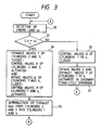
- FIG. 3 is a process flow chart showing one example of the operation of the re-combustion control means for an alcohol engine according to the present invention.
- the control valves 8 are operated by a command from the controller 10 so as to close the combustion gas ports 18.
- the respective cylinders 1, 2, 3, 4 are designed to operate in four-cycle of intake, compression, expansion and exhaust strokes in accordance with commands sent by the controller 10.
- Alcohol fuel is supplied from the fuel injection pump constituting the fuel supply means to the fuel injection nozzles, and alcohol fuel so supplied is then injected from the fuel injection nozzles into the combustion chambers of the respective cylinders 1, 2, 3, 4 or into a suction air passageway communicating with the respective cylinders 1, 2, 3, 4.
- a detection signal sent from the load sensor 14 will be taken to explain detection signals supplied into the controller 10 so as to inform the same of a state in which the engine is being operated in this embodiment. It is needless to say that a signal sent from the revolution sensor 13 informing of the number of revolutions of the engine may be used as a detection signal.
- the volume of alcohol fuel to be supplied from the fuel injection pump to the fuel injection nozzles may be detected.
- a detection signal informing of the volume of alcohol fuel supplied to the fuel injection nozzles is supplied into the controller 10 as a signal informing of the engine load (Step 30).
- the crank angles of the respective cylinders 1, 2, 3, 4 are detected by means of the position sensor 15. These detection signals are then supplied to the controller 10, where which strokes the respective cylinders are currently performing is judged.
- the engine load L E detected by the load sensor 14 is compared to a predetermined engine load L E1 so as to judge which is greater of the two loads (Step 31).
- the engine load L E is judged by the controller 10 as being greater than the predetermined engine load L E1 , the engine is under high load, and it is in a state in which combustion is being actively performed. Therefore, the temperature inside the combustion chambers is high, and the vaporization of alcohol fuel is being promoted, resulting in complete combustion of alcohol fuel. This means that unburnt aldehyde is not contained in exhaust gas, and hence there will be no problem of environmental pollution due to exhaust gas even if it is discharged outside.
- the controller 10 receives a signal informing that the engine is under high load, and sends a command to the valve driving means 9 that the control valves 8 be maintained in a closed state (Step 32), while the intake and exhaust valves 6, 7 are controlled by the associated valve driving means 9 so as to perform opening and closing operations in normal four-cycle sequence (Step 33). Therefore, the combustion chambers of the respective cylinders 1, 2, 3, 4 are put in a state in which combustion is actively being performed, and in this state, the vaporization of alcohol fuel is promoted, and good air-fuel mixture is produced. Therefore, the vaporization of atomized alcohol fuel is also promoted and combustion is effected in a smooth fashion, this preventing the generation of unburnt gas such as aldehyde or the like.
- Step 31 in a case where the engine load L E is judged by the controller 10 as being smaller than the predetermined engine load L E1 , the engine is under low load, and combustion being performed is not strong. In this state, the temperature inside the combustion chambers is low, and therefore the vaporization of alcohol fuel is not sufficient, and alcohol fuel is not able to be completely burned. Unburnt fuel of aldehyde is caused to remain in combustion gas produced in this state, and once such combustion gas is discharged outside as exhaust gas, this causes environmental pollution of odors or irritating odors. However, when the engine is under low load, a high output of the engine is not needed.
- the cylinders 2, 3 out of the four cylinders are driven such that suction air is taken thereinto from the outside, while the cylinders 1, 4 are controlled such that combustion gas produced in the cylinders 2, 3 is introduced thereinto so that combustion gas so taken into is re-burned therein for complete combustion.
- the controller 10 receives a signal informing that the engine is under low load, and sends a command to the valve driving means 9 that the control valves 8 of the respective cylinders 1, 2, 3, 4 be operated so as to be opened or closed, while it drives the valve driving means 9 such that the exhaust valves 7 of the cylinders 2, 3 are maintained in a closed state with the intake valves 6 of the cylinders 1, 4 being maintained in a closed state (Step 34).
- the cylinders 2, 3 take thereinto suction air from the outside or air-fuel mixture of alcohol fuel via the intake pipe and the intake ports 16, and air-fuel mixture of alcohol fuel and suction air is burned with combustion gas so produced being discharged outside from the combustion gas port via the combustion gas passageway 11, while the cylinders 1, 4 take thereinto combustion gas from the combustion gas ports 18 via the combustion gas passageway 11 so that combustion gas so taken into is re-burned therein for complete combustion with exhaust gas resulting from the complete combustion being discharged outside from the exhaust ports 17 via the exhaust pipe (Step 35).
Landscapes
- Engineering & Computer Science (AREA)
- Chemical & Material Sciences (AREA)
- Combustion & Propulsion (AREA)
- Mechanical Engineering (AREA)
- General Engineering & Computer Science (AREA)
- Output Control And Ontrol Of Special Type Engine (AREA)
- Exhaust-Gas Circulating Devices (AREA)
- Combined Controls Of Internal Combustion Engines (AREA)
Applications Claiming Priority (2)
| Application Number | Priority Date | Filing Date | Title |
|---|---|---|---|
| JP281919/89 | 1989-10-31 | ||
| JP1281919A JPH0658094B2 (ja) | 1989-10-31 | 1989-10-31 | アルコールエンジンの再燃焼制御装置 |
Publications (2)
| Publication Number | Publication Date |
|---|---|
| EP0426320A1 true EP0426320A1 (fr) | 1991-05-08 |
| EP0426320B1 EP0426320B1 (fr) | 1994-05-25 |
Family
ID=17645782
Family Applications (1)
| Application Number | Title | Priority Date | Filing Date |
|---|---|---|---|
| EP90311186A Expired - Lifetime EP0426320B1 (fr) | 1989-10-31 | 1990-10-12 | Dispositif de réglage de recombustion pour un moteur à alcool |
Country Status (4)
| Country | Link |
|---|---|
| US (1) | US5115790A (fr) |
| EP (1) | EP0426320B1 (fr) |
| JP (1) | JPH0658094B2 (fr) |
| DE (2) | DE69009142T2 (fr) |
Cited By (3)
| Publication number | Priority date | Publication date | Assignee | Title |
|---|---|---|---|---|
| FR2777947A1 (fr) * | 1998-04-27 | 1999-10-29 | Inst Francais Du Petrole | Procede de combustion par auto-allumage controle et moteur 4 temps associe avec conduit de transfert entre cylindres et soupape dediee |
| FR2799797A1 (fr) * | 1999-10-15 | 2001-04-20 | Jean Louis Rico | Procede et dispositif d'alimentation d'un moteur a combustion interne, en particulier pour vehicule automobile |
| US6880500B2 (en) | 2002-10-04 | 2005-04-19 | Honeywell International, Inc. | Internal combustion engine system |
Families Citing this family (22)
| Publication number | Priority date | Publication date | Assignee | Title |
|---|---|---|---|---|
| JPH04272463A (ja) * | 1991-02-27 | 1992-09-29 | Fuji Heavy Ind Ltd | Ffv用エンジンのegr制御方法 |
| US5323748A (en) * | 1991-08-28 | 1994-06-28 | Massachusetts Institute Of Technology | Adaptive dilution control system for increasing engine efficiencies and reducing emissions |
| GB9222353D0 (en) * | 1992-10-23 | 1992-12-09 | Ricardo Consulting Eng | Spark ignited internal combustion engines |
| US5582155A (en) * | 1994-08-01 | 1996-12-10 | Knopp's Auto Repair, Inc. | Combustion engine with side ports |
| US5460129A (en) * | 1994-10-03 | 1995-10-24 | Ford Motor Company | Method to reduce engine emissions due to misfire |
| DE19621530C1 (de) * | 1996-05-29 | 1997-06-05 | Daimler Benz Ag | Verfahren zur Verminderung der Schadstoffemission einer mehrzylindrigen Brennkraftmaschine |
| JPH11351066A (ja) * | 1998-06-05 | 1999-12-21 | Mitsubishi Electric Corp | 排気ガス還流装置 |
| WO2000001930A2 (fr) | 1998-06-30 | 2000-01-13 | Siemens Canada Limited | Soupape et systeme de rge a injecteur |
| AT3761U1 (de) * | 1998-09-18 | 2000-07-25 | Avl List Gmbh | Brennkraftmaschine, insbesondere diesel-brennkraftmaschine |
| DE19849914C1 (de) * | 1998-10-29 | 1999-11-04 | Daimler Chrysler Ag | Brennkraftmaschine mit einem separat betätigbaren Zusatzventil im Zylinderkopf |
| US6386154B1 (en) * | 2000-06-12 | 2002-05-14 | The United States Of America As Represented By The Administrator Of The Environmental Protection Agency | Pumped EGR system |
| US6553959B2 (en) * | 2000-06-13 | 2003-04-29 | Visteon Global Technologies, Inc. | Electronic flow control for a stratified EGR system |
| DE10107268A1 (de) * | 2001-02-16 | 2002-08-22 | Volkswagen Ag | Verfahren zum Betreiben einer direkteinspritzenden Brennkraftmaschine |
| EP1366279B1 (fr) | 2002-01-31 | 2006-10-18 | Mazda Motor Corporation | Dispositif de commande destine a un moteur a explosion |
| JP3963144B2 (ja) * | 2002-10-04 | 2007-08-22 | マツダ株式会社 | 火花点火式エンジンの制御装置 |
| US7182050B2 (en) | 2002-01-31 | 2007-02-27 | Mazda Motor Corporation | Control device for spark-ignition engine |
| DE102005001757A1 (de) * | 2005-01-14 | 2006-07-20 | Daimlerchrysler Ag | Brennkraftmaschine mit einem den Zylindern zugeordneten Gasdruckbehälter und Verfahren zum Betrieb der Brennkraftmaschine |
| US8146572B2 (en) * | 2009-12-21 | 2012-04-03 | Chrysler Group Llc | Cooled exhaust gas recirculation system with cylinder-level control |
| US9399945B2 (en) | 2011-08-29 | 2016-07-26 | Toyota Jidosha Kabushiki Kaisha | Control device of internal-combustion engine |
| US9291110B2 (en) | 2011-08-29 | 2016-03-22 | Toyota Jidosha Kabushiki Kaisha | Control device for internal combustion engine |
| US10605209B2 (en) * | 2015-10-28 | 2020-03-31 | Cummins Inc. | Thermal management via exhaust gas recirculation |
| US11352968B1 (en) * | 2021-06-29 | 2022-06-07 | Ford Global Technologies, Llc | Methods and systems for reducing catalyst cooling during fuel cut via pre-chamber ignition system |
Citations (4)
| Publication number | Priority date | Publication date | Assignee | Title |
|---|---|---|---|---|
| US3789807A (en) * | 1972-06-19 | 1974-02-05 | J Pinkerton | Dual combustion process for an internal combustion engine |
| US4109625A (en) * | 1976-01-31 | 1978-08-29 | Isuzu Motors Limited | Exhaust gas purifying device for internal combustion engine with auxiliary combustion chambers |
| DE2827630A1 (de) * | 1977-12-02 | 1979-06-07 | Toyota Motor Co Ltd | Mehrzylinder-brennkraftmaschine mit abgasrezirkulierung |
| DE3007927A1 (de) * | 1980-03-01 | 1981-09-17 | Daimler-Benz Ag, 7000 Stuttgart | Mit homogenem gas betriebene, fremdgezuendete brennkraftmaschine |
Family Cites Families (10)
| Publication number | Priority date | Publication date | Assignee | Title |
|---|---|---|---|---|
| DE2740045A1 (de) * | 1977-09-06 | 1979-03-15 | Bayerische Motoren Werke Ag | Verfahren zur teillast-steuerung von brennkraftmaschinen |
| JPS6022170B2 (ja) * | 1977-12-02 | 1985-05-31 | トヨタ自動車株式会社 | 多気筒内燃機関の燃焼促進装置 |
| DE3125647A1 (de) * | 1981-06-30 | 1983-01-13 | Robert Bosch Gmbh, 7000 Stuttgart | "brennkraftmaschine mit mehreren zylindern" |
| JPS5867959A (ja) * | 1981-10-19 | 1983-04-22 | Nissan Motor Co Ltd | アルコ−ル改質ガスエンジンのインテ−クマニホ−ルド |
| JPS58117345A (ja) * | 1981-12-29 | 1983-07-12 | Nissan Motor Co Ltd | アルコ−ル改質ガスエンジンの混合気制御装置 |
| DE3243194A1 (de) * | 1982-11-23 | 1984-05-24 | Degussa Ag, 6000 Frankfurt | Verfahren zur herstellung von siliconkautschuk-vulkanisaten |
| DE3401362C3 (de) * | 1983-02-04 | 1998-03-26 | Fev Motorentech Gmbh | Verfahren zur Steuerung von Viertakt-Kolbenbrennkraftmaschinen |
| GB2161212A (en) * | 1984-04-07 | 1986-01-08 | Jaguar Cars | Cracking fuel and supplying to an internal combustion engine |
| US4875455A (en) * | 1987-04-28 | 1989-10-24 | Mazda Motor Corporation | Automobile exhaust gas recirculating system |
| US4945870A (en) * | 1988-07-29 | 1990-08-07 | Magnavox Government And Industrial Electronics Company | Vehicle management computer |
-
1989
- 1989-10-31 JP JP1281919A patent/JPH0658094B2/ja not_active Expired - Lifetime
-
1990
- 1990-10-04 US US07/593,447 patent/US5115790A/en not_active Expired - Fee Related
- 1990-10-12 DE DE69009142T patent/DE69009142T2/de not_active Expired - Fee Related
- 1990-10-12 DE DE199090311186T patent/DE426320T1/de active Pending
- 1990-10-12 EP EP90311186A patent/EP0426320B1/fr not_active Expired - Lifetime
Patent Citations (4)
| Publication number | Priority date | Publication date | Assignee | Title |
|---|---|---|---|---|
| US3789807A (en) * | 1972-06-19 | 1974-02-05 | J Pinkerton | Dual combustion process for an internal combustion engine |
| US4109625A (en) * | 1976-01-31 | 1978-08-29 | Isuzu Motors Limited | Exhaust gas purifying device for internal combustion engine with auxiliary combustion chambers |
| DE2827630A1 (de) * | 1977-12-02 | 1979-06-07 | Toyota Motor Co Ltd | Mehrzylinder-brennkraftmaschine mit abgasrezirkulierung |
| DE3007927A1 (de) * | 1980-03-01 | 1981-09-17 | Daimler-Benz Ag, 7000 Stuttgart | Mit homogenem gas betriebene, fremdgezuendete brennkraftmaschine |
Non-Patent Citations (1)
| Title |
|---|
| PATENT ABSTRACTS OF JAPAN vol. 7, no. 223 (M-247)(1368) 4 October 1983, & JP-A-58 117345 (NISSAN JIDOSHA K.K.) 12 July 1983, * |
Cited By (5)
| Publication number | Priority date | Publication date | Assignee | Title |
|---|---|---|---|---|
| FR2777947A1 (fr) * | 1998-04-27 | 1999-10-29 | Inst Francais Du Petrole | Procede de combustion par auto-allumage controle et moteur 4 temps associe avec conduit de transfert entre cylindres et soupape dediee |
| EP0953745A1 (fr) * | 1998-04-27 | 1999-11-03 | Institut Francais Du Petrole | Procédé de combustion par auto-allumage contrÔlé et moteur 4 temps associé avec conduit de transfert entre cylindres et soupape dédiée |
| US6427644B1 (en) | 1998-04-27 | 2002-08-06 | Institut Francais Du Petrole | Controlled self-ignition combustion process and associated four-stroke engine with transfer line between cylinders and dedicated value |
| FR2799797A1 (fr) * | 1999-10-15 | 2001-04-20 | Jean Louis Rico | Procede et dispositif d'alimentation d'un moteur a combustion interne, en particulier pour vehicule automobile |
| US6880500B2 (en) | 2002-10-04 | 2005-04-19 | Honeywell International, Inc. | Internal combustion engine system |
Also Published As
| Publication number | Publication date |
|---|---|
| DE426320T1 (de) | 1991-10-17 |
| JPH0658094B2 (ja) | 1994-08-03 |
| US5115790A (en) | 1992-05-26 |
| EP0426320B1 (fr) | 1994-05-25 |
| DE69009142D1 (de) | 1994-06-30 |
| DE69009142T2 (de) | 1994-10-20 |
| JPH03145557A (ja) | 1991-06-20 |
Similar Documents
| Publication | Publication Date | Title |
|---|---|---|
| US5115790A (en) | Re-combustion control means for alcohol engine | |
| EP0967372B1 (fr) | Moteur à combustion interne à deux combustibles avec allumage d'un mélange homogène de gaz, d'air et d'un combustible-pilote | |
| EP1389679B1 (fr) | Moteur thermique a allumage par compression | |
| US5454356A (en) | Engine with pre-chamber | |
| CN1934340B (zh) | 运行压缩点火发动机的方法和压缩点火发动机 | |
| US7743753B2 (en) | Ignition system utilizing igniter and gas injector | |
| CN102852659B (zh) | 缸内喷射式发动机的控制装置 | |
| KR100679065B1 (ko) | 내연기관의 연소과정을 제어하는 방법 및 실린더의 유효압축비를 변화시키기 위한 수단을 구비한 엔진 | |
| EP1379763B1 (fr) | Moteur a auto-allumage a quatre temps | |
| US20020000209A1 (en) | Direct injection type internal combustion engine and controlling method therefor | |
| WO2001046572A1 (fr) | Moteur a quatre courses | |
| US10105650B2 (en) | Multi-pulse injection events for a dual-fuel engine | |
| JP4457054B2 (ja) | 予混合の燃焼制御装置 | |
| US6474291B2 (en) | Clean shutdown for internal combustion engine with variable valve timing | |
| JP2005256734A (ja) | 筒内噴射エンジン | |
| JP2782843B2 (ja) | アルコールエンジン | |
| JP4102268B2 (ja) | 圧縮着火内燃機関 | |
| EP0588592A1 (fr) | Moteur à combustion interne à haut taux de compression | |
| JPH06159061A (ja) | セラミックバルブを用いたガスエンジン | |
| JP2000204989A (ja) | 電磁力駆動装置を備えた副室式ガスエンジン | |
| JPH03117641A (ja) | アルコールエンジン | |
| JPH04117147U (ja) | 圧縮比可変エンジン | |
| JP2000054831A (ja) | 内燃機関の2次空気供給装置 | |
| JP2000073826A (ja) | 内燃機関の制御装置及び制御方法 | |
| JPS58222912A (ja) | デイ−ゼルエンジンの燃料供給装置 |
Legal Events
| Date | Code | Title | Description |
|---|---|---|---|
| PUAI | Public reference made under article 153(3) epc to a published international application that has entered the european phase |
Free format text: ORIGINAL CODE: 0009012 |
|
| AK | Designated contracting states |
Kind code of ref document: A1 Designated state(s): DE GB |
|
| 17P | Request for examination filed |
Effective date: 19910506 |
|
| DET | De: translation of patent claims | ||
| 17Q | First examination report despatched |
Effective date: 19920622 |
|
| GRAA | (expected) grant |
Free format text: ORIGINAL CODE: 0009210 |
|
| AK | Designated contracting states |
Kind code of ref document: B1 Designated state(s): DE GB |
|
| REF | Corresponds to: |
Ref document number: 69009142 Country of ref document: DE Date of ref document: 19940630 |
|
| PGFP | Annual fee paid to national office [announced via postgrant information from national office to epo] |
Ref country code: GB Payment date: 19941003 Year of fee payment: 5 |
|
| PGFP | Annual fee paid to national office [announced via postgrant information from national office to epo] |
Ref country code: DE Payment date: 19941123 Year of fee payment: 5 |
|
| PLBE | No opposition filed within time limit |
Free format text: ORIGINAL CODE: 0009261 |
|
| STAA | Information on the status of an ep patent application or granted ep patent |
Free format text: STATUS: NO OPPOSITION FILED WITHIN TIME LIMIT |
|
| 26N | No opposition filed | ||
| PG25 | Lapsed in a contracting state [announced via postgrant information from national office to epo] |
Ref country code: GB Effective date: 19951012 |
|
| GBPC | Gb: european patent ceased through non-payment of renewal fee |
Effective date: 19951012 |
|
| PG25 | Lapsed in a contracting state [announced via postgrant information from national office to epo] |
Ref country code: DE Effective date: 19960702 |