EP0425762B1 - Extrusionszylinder - Google Patents
Extrusionszylinder Download PDFInfo
- Publication number
- EP0425762B1 EP0425762B1 EP90112889A EP90112889A EP0425762B1 EP 0425762 B1 EP0425762 B1 EP 0425762B1 EP 90112889 A EP90112889 A EP 90112889A EP 90112889 A EP90112889 A EP 90112889A EP 0425762 B1 EP0425762 B1 EP 0425762B1
- Authority
- EP
- European Patent Office
- Prior art keywords
- bush
- extrusion cylinder
- bushes
- steel jacket
- extrusion
- Prior art date
- Legal status (The legal status is an assumption and is not a legal conclusion. Google has not performed a legal analysis and makes no representation as to the accuracy of the status listed.)
- Expired - Lifetime
Links
- 238000001125 extrusion Methods 0.000 title claims abstract description 18
- 229910000831 Steel Inorganic materials 0.000 claims abstract description 22
- 239000010959 steel Substances 0.000 claims abstract description 22
- 239000004033 plastic Substances 0.000 claims abstract description 10
- 229920003023 plastic Polymers 0.000 claims abstract description 10
- 238000000034 method Methods 0.000 claims abstract description 9
- 239000002184 metal Substances 0.000 claims abstract description 5
- 239000000463 material Substances 0.000 claims abstract description 3
- 239000003086 colorant Substances 0.000 abstract description 2
- 230000007257 malfunction Effects 0.000 abstract 1
- 239000000919 ceramic Substances 0.000 description 5
- 238000001746 injection moulding Methods 0.000 description 2
- 238000004519 manufacturing process Methods 0.000 description 2
- 241001295925 Gegenes Species 0.000 description 1
- 239000000945 filler Substances 0.000 description 1
- 239000008187 granular material Substances 0.000 description 1
- 238000010438 heat treatment Methods 0.000 description 1
- 238000009434 installation Methods 0.000 description 1
- 239000011224 oxide ceramic Substances 0.000 description 1
- 229910052574 oxide ceramic Inorganic materials 0.000 description 1
- 239000000843 powder Substances 0.000 description 1
Images
Classifications
-
- B—PERFORMING OPERATIONS; TRANSPORTING
- B29—WORKING OF PLASTICS; WORKING OF SUBSTANCES IN A PLASTIC STATE IN GENERAL
- B29C—SHAPING OR JOINING OF PLASTICS; SHAPING OF MATERIAL IN A PLASTIC STATE, NOT OTHERWISE PROVIDED FOR; AFTER-TREATMENT OF THE SHAPED PRODUCTS, e.g. REPAIRING
- B29C48/00—Extrusion moulding, i.e. expressing the moulding material through a die or nozzle which imparts the desired form; Apparatus therefor
- B29C48/25—Component parts, details or accessories; Auxiliary operations
- B29C48/36—Means for plasticising or homogenising the moulding material or forcing it through the nozzle or die
- B29C48/50—Details of extruders
- B29C48/68—Barrels or cylinders
-
- B—PERFORMING OPERATIONS; TRANSPORTING
- B29—WORKING OF PLASTICS; WORKING OF SUBSTANCES IN A PLASTIC STATE IN GENERAL
- B29C—SHAPING OR JOINING OF PLASTICS; SHAPING OF MATERIAL IN A PLASTIC STATE, NOT OTHERWISE PROVIDED FOR; AFTER-TREATMENT OF THE SHAPED PRODUCTS, e.g. REPAIRING
- B29C48/00—Extrusion moulding, i.e. expressing the moulding material through a die or nozzle which imparts the desired form; Apparatus therefor
- B29C48/03—Extrusion moulding, i.e. expressing the moulding material through a die or nozzle which imparts the desired form; Apparatus therefor characterised by the shape of the extruded material at extrusion
Definitions
- the invention relates to a method for producing an extrusion cylinder for the extrusion of plastics at high working temperatures.
- the ceramic inserts may become loose during operation.
- a wear insert for the screw housing of a twin-screw extrusion press or injection molding machine is known from the publication DE 24 23 785 B1.
- This known machine does not have a steel casing, rather there are several screw housings or housing sections which are axially braced.
- the wear inserts should be slightly longer than the respective associated worm housing and fixing screws are screwed into a wearing part from each housing section.
- This known machine is a very large machine, 10 to 15 m high, which must be supported on foundation plates which are connected to the base foundation of the machine by means of tie rods.
- Another embodiment of the invention is that the axial clamping of the further bushings is carried out with the aid of a threaded ring guided in the steel jacket.
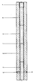
- the steel jacket is labeled 1.
- Cans 2 to 5 are arranged in it, for example cans made of hard metal. It is important in this arrangement that the bushings 2 to 5 lie firmly against one another during extrusion or afterwards. This means that there must not be any gap between the individual bushings, because plastic could penetrate this, for example when extruding another plastic with a different color that would interfere.
- the first bushing 2 is shrunk into the steel jacket 1.
- the bush 2 is then locked in the axial direction, for example with the aid of a screw 6 guided radially in the steel jacket 1.
- the steel jacket 1 is heated again and the further sleeves 3, 4 and 5 are shrunk into the steel jacket 1.
- a threaded ring 7 is screwed into the steel jacket 1 and slightly tightened, so that the further bushes 3, 4 and 5 are axially clamped against the first bushing.
- the entire unit, consisting of steel jacket 1 and bushings 2 to 5 used, can then be cooled to room temperature. In this way, an extrusion cylinder has been obtained which has no loosening of the bushings 2 to 5 used, even at high working temperatures and large temperature fluctuations.
Landscapes
- Engineering & Computer Science (AREA)
- Mechanical Engineering (AREA)
- Extrusion Moulding Of Plastics Or The Like (AREA)
- Pistons, Piston Rings, And Cylinders (AREA)
- Glass Compositions (AREA)
Description
- Die Erfindung betrifft ein Verfahren zum Herstellen eines Extrusionszylinders für die Extrusion von Kunststoffen bei hohen Arbeitstemperaturen.
- Bei der Verarbeitung von Kunststoffen ist es bekannt, beispielsweise Kunststoff-Pulver oder -Granulat mit Hilfe einer Schnecke unter Aufheizung zu plastifizieren und zu extrudieren. Die Schnecke befindet sich in einem Zylinder, der im einfachsten Fall aus Stahl besteht. Je nach zu verarbeitendem Kunststoff oder auch beispielsweise beim Extrudieren von Oxydkeramik sowie Kunststoffen mit hohen Füllstoffanteilen kommt es zu großem Verschleiß des Zylinders.
- Aus der Druckschrift DE 34 37 559 A1 ist ein Verfahren zur Herstellung eines verschleißfesten Arbeitsraumes, vorzugsweise für Spritzgießmaschinen und Extruder, sowie ein danach hergestellter verschleißfester Arbeitsraum bekannt. Gemäß dieser Druckschrift soll vor dem Einfügen von Keramikeinsätzen in ein Trägergehäuse eine Vorspannung dieser Keramikeinsätze mit Hilfe eines Zugankers erfolgen. D.h. vor dem Einbau werden die Keramikeinsätze zusammengepreßt und befinden sich dann in dem Trägergehäuse. Während des späteren Betriebs sind diese Keramikeinsätze nicht arretiert oder verspannt.
- Somit kann es vorkommen, daß sich während des Betriebs die Keramikeinsätze lockern.
- Aus der Druckschrift DE 24 23 785 B1 ist ein Verschleißeinsatz für das Schneckengehäuse einer Doppelschneckenstrangpresse oder -spritzgießmaschine bekannt. Diese bekannte Maschine weist keinen Stahlmantel auf, vielmehr sind mehrere Schneckengehäuse bzw. Gehäuseschüsse vorhanden, die axial verspannt sind. Die Verschleißeinsätze sollen etwas länger als das jeweilige zugehörige Schneckengehäuse sein und Fixierschrauben sind von jedem Gehäuseschuß in ein Verschleißteil geschraubt. Es handelt sich bei dieser bekannten Maschine um sehr große Maschinen, 10 bis 15 m hoch, die auf Fundamentplatten abgestützt werden müssen, die mittels Zugankern mit dem Bodenfundament der Maschine verbunden sind.
- Es ist schon versucht worden, dem Extrusionszylinder eine höhere Standzeit dadurch zu verleihen, daß man in ihn Büchsen aus Hartmetall eingesetzt hat. Vor allem wegen der bei einem Extrusionszylinder vorhandenen hohen Betriebstemperaturen kam es insofern zu Störungen, als die Hartmetall-Büchsen sich in dem Stahlmantel lockern können.
- Der Erfindung liegt die Aufgabe zugrunde, ein Verfahren der eingangs näher bezeichneten Art zu schaffen, wobei ein Extrusionszylinder geschaffen wird, der eine lange Haltbarkeit aufweist, ohne daß die aufgezeigten Störungen auftreten, d.h. es sollen insbesondere die Wirkungen der unterschiedlichen Ausdehnungskoeffizienten von Stahl und Hartmetall oder vergleichbarer Werkstoffe ausgeschaltet werden.
- Diese Aufgabe wird durch die folgenden Verfahrensschritte gelöst:
- Einschrumpfen einer ersten Büchse aus Hartmetall in einen Stahlmantel,
- Arretieren der ersten Büchse in axialer Richtung,
- Einschrumpfen weiterer Büchsen in den Stahlmantel,
- Axiales Verspannen der weiteren Büchsen gegen die erste Büchse.
- Eine weitere Ausbildung der Erfindung besteht darin, daß das Arretieren der ersten Büchse in axialer Richtung mittels einer in dem Stahlmantel radial geführten Schraube erfolgt.
- Eine andere erfindungsgemäße Ausbildung besteht darin, daß das axiale Verspannen der weiteren Büchsen mit Hilfe eines in dem Stahlmantel geführten Gewinderinges erfolgt.
- Die mit der Erfindung erzielten Vorteile bestehen insbesondere darin, daß ein Extrusionszylinder geschaffen worden ist, der eine lange Gebrauchszeit hat und der schnell für verschiedene Extrusionsprozesse einsetzbar ist, beispielsweise beim Extrudieren von Kunststoffen unterschiedlicher Farbe.
- Ein Ausführungsbeispiel eines mit dem erfindungsgemäßen Verfahren geschaffenen Extrusionszylinders ist in der Zeichnung dargestellt und wird im folgenden näher beschrieben.
- In der Zeichnung ist der Stahlmantel mit 1 bezeichnet. In ihm sind Büchsen 2 bis 5 angeordnet, beispielsweise Büchsen aus Hartmetall. Es kommt bei dieser Anordnung darauf an, daß beim Extrudieren oder auch danach die Büchsen 2 bis 5 fest aneinander liegen. Das bedeutet, es darf zwischen den einzelnen Büchsen kein Spalt entstehen, weil in diesen Kunststoff eindringen könnte, der beim Extrudieren eines anderen Kunststoffes, beispielsweise mit einer anderen Farbe, sich störend auswirken würde.
- Erfindungsgemäß wird die erste Büchse 2 in den Stahlmantel 1 eingeschrumpft. Die Büchse 2 wird dann beispielsweise mit Hilfe einer in dem Stahlmantel 1 radial geführten Schraube 6 in axialer Richtung arretiert. Es können am Umfang des Stahlmantels 1 mehrere Schrauben 6 vorhanden sein. Nach dem Arretieren in axialer Richtung durch die Schraube 6 der Büchse 2 wird der Stahlmantel 1 erneut erwärmt und die weiteren Büchsen 3, 4 und 5 in den Stahlmantel 1 eingeschrumpft. Noch bei erhöhter Schrumpf-Temperatur wird in den Stahlmantel 1 ein Gewindering 7 eingedreht und leicht angezogen, so daß die weiteren Büchsen 3, 4 und 5 axial gegen die erste Büchse verspannt sind. Danach kann das gesamte Aggregat, bestehend aus Stahlmantel 1 und eingesetzten Büchsen 2 bis 5 auf Raumtemperatur abgekühlt werden. Auf diese Weise hat man einen Extrusionszylinder erhalten, der auch bei hohen Arbeitstemperaturen und großen Temperatur-Schwankungen keine Lockerung der eingesetzten Büchsen 2 bis 5 aufweist.
Claims (3)
- Verfahren zum Herstellen eines Extrusionszylinders für die Extrusion von Kunststoffen bei hohen Arbeitstemperaturen, gekennzeichnet durch folgende Verfahrensschritte:· Einschrumpfen einer ersten Büchse (2) aus Hartmetall in einen Stahlmantel (1),· Arretieren der ersten Büchse (2) in axialer Richtung,· Einschrumpfen weiterer Büchsen (3, 4, 5) in den Stahlmantel (1),· Axiales Verspannen der weiteren Büchsen (3, 4, 5) gegen die erste Büchse.
- Verfahren gemäß Anspruch 1, dadurch gekennzeichnet, daß das Arretieren der ersten Büchse (2) in axialer Richtung mittels einer in dem Stahlmantel (1) radial geführten Schraube (6) erfolgt.
- Verfahren gemäß Anspruch 1, dadurch gekennzeichnet, daß das axiale Verspannen der weiteren Büchsen (3, 4, 5) mit Hilfe eines in dem Stahlmantel (1) geführten Gewinderinges (7) erfolgt.
Applications Claiming Priority (3)
| Application Number | Priority Date | Filing Date | Title |
|---|---|---|---|
| DE3935970A DE3935970A1 (de) | 1989-10-28 | 1989-10-28 | Extrusionszylinder |
| DE8912774U DE8912774U1 (de) | 1989-10-28 | 1989-10-28 | Extrusionszylinder |
| DE3935970 | 1989-10-28 |
Publications (3)
| Publication Number | Publication Date |
|---|---|
| EP0425762A2 EP0425762A2 (de) | 1991-05-08 |
| EP0425762A3 EP0425762A3 (en) | 1991-10-30 |
| EP0425762B1 true EP0425762B1 (de) | 1995-09-13 |
Family
ID=25886532
Family Applications (1)
| Application Number | Title | Priority Date | Filing Date |
|---|---|---|---|
| EP90112889A Expired - Lifetime EP0425762B1 (de) | 1989-10-28 | 1990-07-06 | Extrusionszylinder |
Country Status (6)
| Country | Link |
|---|---|
| EP (1) | EP0425762B1 (de) |
| AT (1) | ATE127726T1 (de) |
| DD (1) | DD298220A5 (de) |
| DE (3) | DE8912774U1 (de) |
| DK (1) | DK0425762T3 (de) |
| ES (1) | ES2076266T3 (de) |
Families Citing this family (2)
| Publication number | Priority date | Publication date | Assignee | Title |
|---|---|---|---|---|
| DE102004037978B4 (de) * | 2004-08-05 | 2008-08-07 | Kraussmaffei Technologies Gmbh | Vorrichtung und Verfahren zur Verarbeitung eines Materials und Getriebe zur Verwendung in einer solchen Vorrichtung |
| DE102016119858A1 (de) | 2016-10-18 | 2018-04-19 | Kraussmaffei Technologies Gmbh | Zylinder für eine Kunststoff verarbeitende Maschine |
Family Cites Families (6)
| Publication number | Priority date | Publication date | Assignee | Title |
|---|---|---|---|---|
| DE7236648U (de) * | 1973-03-15 | Frech O | Druckzylinder für Kunststoff-Spritzgießmaschinen | |
| DE2423785C2 (de) * | 1974-05-16 | 1980-06-12 | Werner & Pfleiderer, 7000 Stuttgart | Verschleißeinsatz für das Schneckengehäuse einer Doppelschneckenstrangpresse oder -Spritzgießmaschine |
| DE2558611C3 (de) * | 1975-12-24 | 1982-09-23 | Werner & Pfleiderer, 7000 Stuttgart | Verfahren zum verschleißfesten Auskleiden des Arbeitsraumes von Schneckenextrudern |
| DE3347537A1 (de) * | 1983-12-30 | 1985-09-05 | Josef A. 7144 Asperg Blach | Gehaeuseabschnitt fuer eine doppelschneckenwellenmaschine |
| DE3437559A1 (de) * | 1984-10-12 | 1986-06-26 | Michael Dipl.-Ing. 6500 Mainz Reinhard | Verfahren zur herstellung eines verschleissfesten arbeitsraumes, vorzugsweise fuer spritzgiessmaschinen und fuer ein- und zweiwellige extruder, auch konischer bauart, und ein nach diesem verfahren hergestellter verschleissfester arbeitsraum |
| DE8715487U1 (de) * | 1987-11-23 | 1988-03-10 | Rütten, Karl Heinz, 5014 Kerpen | Massezylinder für Spritzgieß- oder Extrudermaschinen für Kunststoffe |
-
1989
- 1989-10-28 DE DE8912774U patent/DE8912774U1/de not_active Expired - Lifetime
- 1989-10-28 DE DE3935970A patent/DE3935970A1/de active Granted
-
1990
- 1990-07-06 AT AT90112889T patent/ATE127726T1/de not_active IP Right Cessation
- 1990-07-06 ES ES90112889T patent/ES2076266T3/es not_active Expired - Lifetime
- 1990-07-06 DK DK90112889.2T patent/DK0425762T3/da active
- 1990-07-06 EP EP90112889A patent/EP0425762B1/de not_active Expired - Lifetime
- 1990-07-06 DE DE59009651T patent/DE59009651D1/de not_active Expired - Fee Related
- 1990-09-28 DD DD90344274A patent/DD298220A5/de not_active IP Right Cessation
Also Published As
| Publication number | Publication date |
|---|---|
| DD298220A5 (de) | 1992-02-13 |
| DE3935970A1 (de) | 1991-05-02 |
| ATE127726T1 (de) | 1995-09-15 |
| DE59009651D1 (de) | 1995-10-19 |
| EP0425762A3 (en) | 1991-10-30 |
| EP0425762A2 (de) | 1991-05-08 |
| ES2076266T3 (es) | 1995-11-01 |
| DE3935970C2 (de) | 1992-02-13 |
| DE8912774U1 (de) | 1989-12-14 |
| DK0425762T3 (da) | 1995-11-06 |
Similar Documents
| Publication | Publication Date | Title |
|---|---|---|
| EP0562269B1 (de) | Drehdurchführung | |
| DE19652047B4 (de) | Heißkanaldüse mit einem Düsenvorderteil aus einer Karbidlegierung | |
| DE202010017571U1 (de) | Planetwalzenextrudermodul mit segmentiertem Gehäuse | |
| AT391293B (de) | Spritzgiessmaschine | |
| DE4137664B4 (de) | Spritzgießvorrichtung mit gesondertem Heizelement im den Formhohlraum bildenden Einsatz | |
| DE69504330T2 (de) | Abstandeinstellung von einem strömungskanal in einer vorrichtung zum formen von kunststoffteilen | |
| DE102019105681A1 (de) | Formgebungsmaschine und Verfahren zum Betreiben einer Formgebungsmaschine | |
| DE3935856C1 (de) | ||
| DE8110512U1 (de) | Einzugsbuchse fuer einschnecken-extruder" | |
| DE69718559T2 (de) | Vier beheizte Düseverteiler miteinander verbunden in einer gemeinsamen Fläche | |
| DE202008007918U1 (de) | Spritzgießdüse für ein Spritzgießwerkzeug | |
| EP0425762B1 (de) | Extrusionszylinder | |
| EP0691728B1 (de) | Vorrichtung zur Halterung der Stabenden einer Statorwicklung in einer dynamoelektrischen Maschine | |
| DE1928176C3 (de) | Walzenbrikettpresse zum Heißverpressen von Kohle, Erzen und ähnlichen Stoffen | |
| DE2947938A1 (de) | Schnellspannvorrichtung fuer spritz oder druckgussformen | |
| DE3836097C2 (de) | Holmzieh- und Spannvorrichtung, insbesondere für Spritzgießmaschine, Presse | |
| EP0316561A1 (de) | Kunststoff-Spritzgiesseinheit | |
| DE2340499B1 (de) | Mehrteilige Schnecke für eine Schnekkenstrangpresse zur Verarbeitung von Kunststoffen | |
| DE2214646C3 (de) | Kunststoff-Spritzgießmaschine mit einer Formschließvorrichtung mit rechteckigem Grundkörper | |
| DE3143748C2 (de) | Form zum Spritzgießen oder Preßspritzen von Kautschuk oder anderen plastischen, wärmehärtbaren Werkstoffen | |
| EP0552447B1 (de) | Spritzgiesseinheit für die Verarbeitung von Kunststoffen und plastischen Materialien | |
| EP0276758A2 (de) | Rückströmsperre für die Plastifizier- und Spritzaggregate für Spritzgiessmaschinen | |
| DE2904883C2 (de) | Druckkolben für Druckgießmaschinen | |
| DE3127506C2 (de) | ||
| DE102015008578B4 (de) | Heißkanaldüse |
Legal Events
| Date | Code | Title | Description |
|---|---|---|---|
| PUAI | Public reference made under article 153(3) epc to a published international application that has entered the european phase |
Free format text: ORIGINAL CODE: 0009012 |
|
| AK | Designated contracting states |
Kind code of ref document: A2 Designated state(s): AT BE CH DE DK ES FR GB IT LI NL |
|
| PUAL | Search report despatched |
Free format text: ORIGINAL CODE: 0009013 |
|
| AK | Designated contracting states |
Kind code of ref document: A3 Designated state(s): AT BE CH DE DK ES FR GB IT LI NL |
|
| 17P | Request for examination filed |
Effective date: 19911204 |
|
| 17Q | First examination report despatched |
Effective date: 19920917 |
|
| GRAA | (expected) grant |
Free format text: ORIGINAL CODE: 0009210 |
|
| ITF | It: translation for a ep patent filed | ||
| AK | Designated contracting states |
Kind code of ref document: B1 Designated state(s): AT BE CH DE DK ES FR GB IT LI NL |
|
| REF | Corresponds to: |
Ref document number: 127726 Country of ref document: AT Date of ref document: 19950915 Kind code of ref document: T |
|
| REF | Corresponds to: |
Ref document number: 59009651 Country of ref document: DE Date of ref document: 19951019 |
|
| ET | Fr: translation filed | ||
| GBT | Gb: translation of ep patent filed (gb section 77(6)(a)/1977) |
Effective date: 19951002 |
|
| REG | Reference to a national code |
Ref country code: ES Ref legal event code: FG2A Ref document number: 2076266 Country of ref document: ES Kind code of ref document: T3 |
|
| REG | Reference to a national code |
Ref country code: DK Ref legal event code: T3 |
|
| PGFP | Annual fee paid to national office [announced via postgrant information from national office to epo] |
Ref country code: DE Payment date: 19960612 Year of fee payment: 7 |
|
| PGFP | Annual fee paid to national office [announced via postgrant information from national office to epo] |
Ref country code: GB Payment date: 19960617 Year of fee payment: 7 |
|
| PLBI | Opposition filed |
Free format text: ORIGINAL CODE: 0009260 |
|
| PG25 | Lapsed in a contracting state [announced via postgrant information from national office to epo] |
Ref country code: DK Effective date: 19960706 Ref country code: AT Effective date: 19960706 |
|
| REG | Reference to a national code |
Ref country code: DK Ref legal event code: EBP |
|
| PG25 | Lapsed in a contracting state [announced via postgrant information from national office to epo] |
Ref country code: ES Free format text: LAPSE BECAUSE OF THE APPLICANT RENOUNCES Effective date: 19960708 |
|
| PLBF | Reply of patent proprietor to notice(s) of opposition |
Free format text: ORIGINAL CODE: EPIDOS OBSO |
|
| PG25 | Lapsed in a contracting state [announced via postgrant information from national office to epo] |
Ref country code: LI Effective date: 19960731 Ref country code: CH Effective date: 19960731 Ref country code: BE Effective date: 19960731 |
|
| 26 | Opposition filed |
Opponent name: HERMANN BERSTORFF MASCHINENBAU GMBH Effective date: 19960612 |
|
| NLR1 | Nl: opposition has been filed with the epo |
Opponent name: HERMANN BERSTORFF MASCHINENBAU GMBH |
|
| PLBF | Reply of patent proprietor to notice(s) of opposition |
Free format text: ORIGINAL CODE: EPIDOS OBSO |
|
| BERE | Be: lapsed |
Owner name: SAAR-HARTMETALL UND WERKZEUGE G.M.B.H. Effective date: 19960731 |
|
| PG25 | Lapsed in a contracting state [announced via postgrant information from national office to epo] |
Ref country code: NL Effective date: 19970201 |
|
| REG | Reference to a national code |
Ref country code: CH Ref legal event code: PL |
|
| PG25 | Lapsed in a contracting state [announced via postgrant information from national office to epo] |
Ref country code: FR Effective date: 19970328 |
|
| NLV4 | Nl: lapsed or anulled due to non-payment of the annual fee |
Effective date: 19970201 |
|
| REG | Reference to a national code |
Ref country code: FR Ref legal event code: ST |
|
| PG25 | Lapsed in a contracting state [announced via postgrant information from national office to epo] |
Ref country code: GB Free format text: LAPSE BECAUSE OF NON-PAYMENT OF DUE FEES Effective date: 19970706 |
|
| GBPC | Gb: european patent ceased through non-payment of renewal fee |
Effective date: 19970706 |
|
| PG25 | Lapsed in a contracting state [announced via postgrant information from national office to epo] |
Ref country code: DE Free format text: LAPSE BECAUSE OF NON-PAYMENT OF DUE FEES Effective date: 19980401 |
|
| PLBO | Opposition rejected |
Free format text: ORIGINAL CODE: EPIDOS REJO |
|
| PLBN | Opposition rejected |
Free format text: ORIGINAL CODE: 0009273 |
|
| STAA | Information on the status of an ep patent application or granted ep patent |
Free format text: STATUS: OPPOSITION REJECTED |
|
| 27O | Opposition rejected |
Effective date: 19980710 |
|
| REG | Reference to a national code |
Ref country code: ES Ref legal event code: FD2A Effective date: 20001009 |
|
| PG25 | Lapsed in a contracting state [announced via postgrant information from national office to epo] |
Ref country code: IT Free format text: LAPSE BECAUSE OF NON-PAYMENT OF DUE FEES;WARNING: LAPSES OF ITALIAN PATENTS WITH EFFECTIVE DATE BEFORE 2007 MAY HAVE OCCURRED AT ANY TIME BEFORE 2007. THE CORRECT EFFECTIVE DATE MAY BE DIFFERENT FROM THE ONE RECORDED. Effective date: 20050706 |