EP0421793A2 - Verfahren für Steuerungsregelerzeugung und Methode zur zerstreuten Steuerung, das gleiche Verfahren benutzend und Gerät zur automatischen Steuerungsregelerzeugung und zerstreutes Steuerungsgerät dasselbe Gerät benutzend - Google Patents
Verfahren für Steuerungsregelerzeugung und Methode zur zerstreuten Steuerung, das gleiche Verfahren benutzend und Gerät zur automatischen Steuerungsregelerzeugung und zerstreutes Steuerungsgerät dasselbe Gerät benutzend Download PDFInfo
- Publication number
- EP0421793A2 EP0421793A2 EP90310890A EP90310890A EP0421793A2 EP 0421793 A2 EP0421793 A2 EP 0421793A2 EP 90310890 A EP90310890 A EP 90310890A EP 90310890 A EP90310890 A EP 90310890A EP 0421793 A2 EP0421793 A2 EP 0421793A2
- Authority
- EP
- European Patent Office
- Prior art keywords
- control
- value
- measured
- rule
- values
- Prior art date
- Legal status (The legal status is an assumption and is not a legal conclusion. Google has not performed a legal analysis and makes no representation as to the accuracy of the status listed.)
- Withdrawn
Links
Images


Classifications
-
- G—PHYSICS
- G06—COMPUTING OR CALCULATING; COUNTING
- G06N—COMPUTING ARRANGEMENTS BASED ON SPECIFIC COMPUTATIONAL MODELS
- G06N5/00—Computing arrangements using knowledge-based models
- G06N5/04—Inference or reasoning models
- G06N5/048—Fuzzy inferencing
-
- G—PHYSICS
- G05—CONTROLLING; REGULATING
- G05B—CONTROL OR REGULATING SYSTEMS IN GENERAL; FUNCTIONAL ELEMENTS OF SUCH SYSTEMS; MONITORING OR TESTING ARRANGEMENTS FOR SUCH SYSTEMS OR ELEMENTS
- G05B13/00—Adaptive control systems, i.e. systems automatically adjusting themselves to have a performance which is optimum according to some preassigned criterion
- G05B13/02—Adaptive control systems, i.e. systems automatically adjusting themselves to have a performance which is optimum according to some preassigned criterion electric
- G05B13/0265—Adaptive control systems, i.e. systems automatically adjusting themselves to have a performance which is optimum according to some preassigned criterion electric the criterion being a learning criterion
- G05B13/0275—Adaptive control systems, i.e. systems automatically adjusting themselves to have a performance which is optimum according to some preassigned criterion electric the criterion being a learning criterion using fuzzy logic only
-
- G—PHYSICS
- G06—COMPUTING OR CALCULATING; COUNTING
- G06N—COMPUTING ARRANGEMENTS BASED ON SPECIFIC COMPUTATIONAL MODELS
- G06N5/00—Computing arrangements using knowledge-based models
- G06N5/02—Knowledge representation; Symbolic representation
- G06N5/022—Knowledge engineering; Knowledge acquisition
-
- G—PHYSICS
- G06—COMPUTING OR CALCULATING; COUNTING
- G06N—COMPUTING ARRANGEMENTS BASED ON SPECIFIC COMPUTATIONAL MODELS
- G06N5/00—Computing arrangements using knowledge-based models
- G06N5/04—Inference or reasoning models
-
- Y—GENERAL TAGGING OF NEW TECHNOLOGICAL DEVELOPMENTS; GENERAL TAGGING OF CROSS-SECTIONAL TECHNOLOGIES SPANNING OVER SEVERAL SECTIONS OF THE IPC; TECHNICAL SUBJECTS COVERED BY FORMER USPC CROSS-REFERENCE ART COLLECTIONS [XRACs] AND DIGESTS
- Y10—TECHNICAL SUBJECTS COVERED BY FORMER USPC
- Y10S—TECHNICAL SUBJECTS COVERED BY FORMER USPC CROSS-REFERENCE ART COLLECTIONS [XRACs] AND DIGESTS
- Y10S706/00—Data processing: artificial intelligence
- Y10S706/90—Fuzzy logic
Definitions
- This invention relates to a method and apparatus for generating control rules used for expert systems and for fuzzy control, and to a method and apparatus for fuzzy control using the control rules. Particularly, the invention relates to a method and apparatus for automatic control rule generation which are suited to generate optimal control rules automatically without relying on the memory of a skilled operator who operates the control object.
- the scheme of artificial intelligent (AI) control is applied in many fields recently, and the range of application is further expanding.
- This control scheme formulates the human experience into rules, and determines control values based on the rules.
- the control system engineer collects the experience of operators on the operation of the control object and determines the rule based on feeling.
- the experience based on the memory of the operator is much ambiguous and it is necessary to collect much data thereby to remove inconsistent data in order to alleviate the ambiguity.
- the designer himself must know the control object to some extent for creating an optimal rule. If the designer relies on his feeling in generating a rule, it will take inpractically too long time and the rule will lack the reliability due to the inclusion of inconsistent data or the like.
- a large plant is controlled in different manners at the time of start or half, when the dynamic characteristics of the plant varies significantly, and at the time of steady-state operation.
- the steady-state operation in which the variation of the plant dynamic characteristics is small, it is easy to have the PID-based automatic control or the automatic control based on control rules that are created by the application of the above-mentioned prior art.
- a large plant is controlled separately for each storage vessel or piping and control rules must be created for all separate control objects by expending enormous time. This is a problem.
- control rules for the transition to the AI-based operation is entirely dependent on the experience of the operator, and how to form the experience into rules applicable to the practical situation is an imminent problem. Hearing of the operator's experience by the system designer to make control rules will result in the rule generation which depends on the feeling or proficiency of an individual system designer and also in the failure in collecting abundant data.
- a first object of this invention is to provide a method and apparatus for automatic rule generation capable of automatically generating control rules, which is applicable to a large plant for its start or halt control in which the dynamic characteristics varies significantly, without relying on the operator's memory.
- a second object of this invention is to provide a method and apparatus for fuzzy control in which the control object is controlled automatically and properly through the use of control rules that are generated automatically by the method and apparatus for accomplishing the first object of this invention.
- the above first objective is achieved through the measurement of the actual values of states of the control object and the detection of the control values taken in the operation of the control object at the time of each state measurement, and the generation of control rules based on the relation between the detected values.
- the above first objective is also achieved through the measurement of multiple kinds of state values of the control object and the detection of control values for the control object taken in the control operation at the time of each state measurement, with the measured state values and detected control values being memorized in a correspondent manner, the assessment of correlation between the measurement state values and detected control values, and the calculation of regression lines or regression curves through the statistical process for the relation between the state values and control values with the degree of correlation greater than or equal to a prescribed value, and through the generation of control rules for the measured state values based on the regression line or regression curve.
- the above second objective is achieved through the assessment of the reliability of control values for one kind of measured state value from a regression line or regression curve, the assessment of the reliability of control values for another kind of measured state value from another regression line or regression curve, and the operation of the control object using a control value which is based on a weighted average value of the reliabilities of the control values.
- control rules are generated from measured state values and corresponding control values for the control object, the need of hearing the experience of operators is eliminated and the resulting control rules are immune to the subjective sense of the system designer.
- Objective control rules which do not depend on the designer, can be generated automatically in a short time without relying on the memory of a skilled operator.
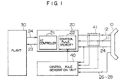
- Fig. 1 is a block diagram of the plant control facility which is equipped with the automatic control rule generation apparatus based on the embodiment of this invention.
- the plant control facility includes a plant 30 as a control object, a plant control unit 20 which controls the plant, and a main control panel 10 on which the operator issues commands to the control unit 20.
- the control unit 20 is a digital computer designed for control.
- the whole plant 30 may be controlled concentrically with a single control unit 20, or may be controlled distributively with a plurality of control units 20. Although the present invention is applicable to both cases, this embodiment is for a single control unit.
- the control unit 20 performs the AI (artificial intelligence) control, sequence control, and PID (proportional plus integral plus delivative) control for operating the plant 30 stably, safely and automatically.
- the plant 30 may be controlled for starting or halting by the manual operation of the operator on the main control panel 10.
- the command signals 11 are entered to the control unit 20, which then responds to the command signals 11 to produce operation signals 23 to the plant 30 so that it is controlled.
- the plant 30 has the installation of various measuring devices, which send measured signals 24 to the control unit 20, which then produces corresponding detected signals 12 to the main control panel 10, on which the measured values are displayed on the respective instruments.
- a control rule generation unit 40 introduces various data and generates a control rule, as will be explained in detail later.
- the generated control rule is added to control rules in the control rule memory 22 for the AI controller 21 provided in the control unit 20 or an older control rule is replaced with the created control rule.
- the addition or replacement of a control rule may be carried out automatically each time a new control rule is created, or, as in this embodiment, it may be implemented by the maintenance staff through the verification and decision on the addition or replacement of the rule in the memory 22 when the plant operation is halted.
- the control rule generation unit 40 introduces the detected signals 12 from the measuring devices and the associated manual command signals 11, and it is designed to introduce the signals 11 and 12 from the control rule generation terminal board 41 for the signal lines running between the main control panel 10 and the control unit 20.
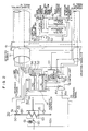
- Fig. 2 is a diagram showing a specific arrangement of the automatic control rule generation unit 40 and control unit 20 in Fig. 1.
- control rule generation unit 40 comprises a data memory 43 which stores the detected signals 12, a control rule generator 46 which creates control rules in accordance with the data in the memory 43, and a control rule memory 42 which stores created control rules.
- the main control panel 10 is used to select the manual operation or automatic control for the plant operation, and in the case of automatic control, it issues an operational mode command signal 24 indicative of the PID control or AI control to the units 20 and 40.
- the main control panel 10 further issues a data store command signal 27 indicative of the storing of the detected signals in the memory 43 to the memory 43 selectively, issues a rule generation made command signal 28 indicative of automatic rule generation under the prescribed condition or rule generation based on the operator's will to the rule generator 46 selectively, and further issues a rule transfer command signal 26, indicative of the transfer of rules stored in the memory 42 to the control rule memory 22, to the memory 42.
- These signals 24-28 are produced by the operator arbitrarily.
- the transfer of the rules in the memory 42 to the memory 22 may be executed automatically upon starting the plant.
- the memory 43 responds to the data store command signal 27 to store the detected signals 12 and the manual command signal 11.
- the control rule generator 46 responds to the signal to generate a rule in accordance with the data in the memory 43, or with the command signal indicating the automatic rule generation, it automatically generates a rule in accordance with the data in the memory 43 at the time point when data enough to generate the rule have been stored in the memory 43 or on expiration of a prescribed time length since the previous rule generation, and it stores the created rule in the memory 42.
- the transfer of rules in the memory 42 to the memory 22 is carried out when the plant operation is halted or AI control is halted, preferably.
- the control unit 20 comprises an automatic controller 14, a control rule memory 22 and a switch unit 16.
- the automatic controller 14 comprises a PID controller 18, an AI controller 21, etc. for example. In this embodiment, only the PID controller and AI controller are included for the sake of simplifying the explanation.
- the PID controller produces a PID control signal as an operation signal in accordance with the measured signals 24, and the AI controller produces an operation signal in accordance with the measured signals 24 and the control rule stored in the memory 22.
- the controllers 18 and 21 are activated in response to the operational mode command signal 24 indicative of the PID control and AI control, respectively.
- the switch unit 16 delivers its output to the input terminal 16b for the operation signal 11 when the operational mode signal 24 indicates the manual operation, delivers the output to the input terminal 16c of the output of AI controller 21 when the mode signal indicates the AI control in automatic operation mode, or delivers the output to the input terminal 16d of the output of PID controller 18 when the mode signal indicates the PID control.
- control rule generation unit 40 Next, the method of control rule generation by the control rule generation unit 40 will be explained.
- state values such as the temperature, pressure and flow rate are measured for each vessel or piping, and control objects are controlled indivisually in response to the measured state values.
- This embodiment explained below, as an example, is a case where the present invention is applied to a cooler which is provided for controlling the temperature of liquid flowing in a process pipe 50.
- the cooler comprises a container 63 which covers part of the process pipe 50, a pump 60 which feeds the liquid into the container 63 and a motor 61 which drives the pump at a controlled rotational speed.
- the flow rate in the container 63 is controlled through the control of the motor 61, thereby controlling the temperature of the liquid flowing in the process pipe 50.
- the operator With the intention of maintaining the liquid temperature inside the process pipe 50, the operator sets manually on the main control panel 10 the rotational speed of the motor 61. In this case, the operator has to determine the motor speed for accomplishing the purpose while observing various instruments on the main control panel 10. However, it is not clear that in what proportion the operator takes the reading of each instrument into account. Therefore, it is desirable to introduce as many instrument information as possible, so far as the computer can deal with, to the automatic control rule generation unit 40 besides the information which is conceived to be indispensable for the determination of the motor speed. The reason is that the plant operator possibly uses several kinds of information unconsciously in determining the control value 62 of the motor 61.
- control signal operation signal
- detected signals 52, 54 and 56 into the memory 43 of the control rule generation unit 40.
- the memory 43 stores a lot of data
- the control rule generator 46 analyzes the data to create a control rule, and stores the generated control rule in the rule storage 42.
- control rule generation by the control rule generator will be explained with reference to the flowchart of Fig. 5.
- stored data is read out of the memory 43.
- the readout data are measured values of the detected signals 52, 54 and 56 in correspondence to the then value of the control signal 62.
- the memory 43 stores the value of the control signal 62 and detected signals 52 and 54 at each time.
- the next step 502 evaluates the correlation coefficient between the measured value of the signal 52 and the value of control signal 62, between the measured value of signal 54 and the value of control signal 62, and between the measured value of signal 56 and the value of control signal 62, and verifies that the values of correlation coefficient are greater than or equal to the prescribed value.
- control rules are created only for the relations between measured values and control values, with their correlation coefficients being judged to be greater than or equal to the prescribed value in step 504.
- This rule generation is to obtain a regression line (or regression curve) between measured values and control values.
- the regression line (or regression curve) is segmented, and the reciplocal of standard deviation of each segment is evaluated in order to know the strength of relation between the two variables (measured value and control value) (step 506).
- the last step 508 stores, as rules, the regression line (regression curve) and the reciplocal of standard deviation of each segment in the rule memory 42.
- the correlation coefficients are calculated based on the following equation from the amount (rate) of change Y in the value of control signal 62, the deviation Xf of the flow rate signal 52 from the normal value (50 l/min), the deviation of the pressure signal 54 from the normal value (50 kPa), and the deviation Xt of the temperature signal 56 from the normal value (100°C).
- Xn is the mean value of Xn
- Y is the mean value of Y
- xn is equal to Xn- Xn
- y is equal to Y- Y .
- a measured value with a subscript of f for n represents the flow rate
- that with a subscript of p for n represents the pressure
- t for n represents the temperature.
- the control rule generation based on this embodiment is carried out separately for the cases of the increasing and decreasing of the control value.
- the correlation coefficient between the two variables (measured value and control value) are expressed by the following variables. rf+: The correlation coefficient between the amount (rate) of variation Y of the control value and the derivation Xf of the flow rate signal 52 from the normal value in the case of increasing the value of the control signal 62. rf-: The correlation coefficient between the Y and Xf in the case of decreasing the value of the control signal 62. rp+: The correlation coefficient between the amount (rate) of variation Y of the control value and the deviation Xp of the pressure signal 54 from the normal value in the case of increasing the value of the control signal 62.
- rp- The correlation coefficient between the Y and Xp in the case of decreasing the value of the control signal 62.
- rt+ The correlation coefficient between the amount (rate) of variation Y of the control value and the deviation Xt of the temperature signal 52 from the normal value in the case of increasing the value of the control signal 62.
- rt- The correlation coefficient between the Y and Xt in the case decreasing the value of the control signal 62.
- This embodiment is designed to make control rules for detected signals with values of correlation coefficient greater than or equal to a prescribed value, e.g., 0.5.
- Correlation coefficients of 0.5 or above are rf+, rf-, ft+ and ft-. Accordingly, control rules are made for the relation between the change in the flow rate signal and the control value and the relation between the change in the temperature signal and the control value.
- No control rule is made for the pressure because of its small correlation with the control value. Since it is not known which kind of measured value is related with the control value, it is necessary to introduce as many kinds of measured information as possible. Among the introduced information, those with small correlation are removed.
- the regression line f(Xf)1 is calculated using the following equations (3), (4) and (5).
- f(Xf)1 a1 + b1Xf (3)
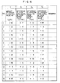
- the regression line of rule 1 is calculated for the data of Fig. 4 as follows.
- the equation (6) is determined from information based on the actual plant operation by the operator and data collected from the measuring devices installed in the plant, and the presence of correlation between the information and data is proved by the equation (2).
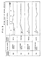
- not all points of Xf in the equation (6) have a high correlation as shown by the data in Fig. 6 for example.
- plots of data scatter from the regression line at intermediate portions of Xn and they have small degree of correlation.
- the range of variable is divided into a prescribed number of segments and the relation between the deviation Xf and the amount (rate) of change Y is evaluated for each segment.
- the reciplocal of the standard deviation ⁇ : i.e., 1/ ⁇ , is calculated as a degree of correlation in each segment.
- the 1/ ⁇ is expressed by the following equation (7).
- control rule generation unit 40 introduces the instrument data and control value data based on the manual operation automatically, and when a certain amount of data have been collected, the control rule generator 46 operates automatically or is activated by the operator thereby to calculate the 1/ ⁇ .
- the generated control rules shown by 8-1 through 11-4 are stored in the memory 42. Accordingly, the operator can have intended control rules automatically at a certain interval or by merely dictating the rule generation when necessary. However, it does not mean that control rules as described above cannot be created unless the automatic control rule generation unit is available. What are needed for the rule generation are actual instrument data and associated control value data based on the manual operation, and therefore it is of course possible to generate control rules by the provision of a magnetic recording unit, for example, in the plant for collecting data and by analyzing the data afterward.
- fuzzy control which uses the control rules created as described above will be explained.
- the fuzzy controller of this embodiment is made operative by storing control rules in the memory 22 of the AI controller 21 in the control unit 200 shown in Fig. 2.
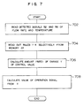
- a method of fuzzy control by the AI controller for carrying out the automatic plant control will be explained on the flowchart of Fig. 7.
- the AI controller 21 is activated in response to the operational mode command signal 24 indicative of AI control, and it introduces detected signals 52, 54 and 56 from the respective measuring devices 51, 53 and 55.
- the controller calculates the deviations Xn of data from the respective normal values, and produces an operation signal 62a to the motor 61 by calculating the amount (rate) of change of control value for the motor 61 with respect to the Xn.
- the pressure of liquid has a smaller correlation coefficient, and it is not taken into consideration in producing the control value signal.
- the AI controller 21 controls the motor speed based on the rules with correlation coefficients greater than or equal to the prescribed value stored in the memory 22, i.e., rules 8-1 through 11-4 for the flow rate and temperature.
- the amount (rate) of change of control value to be obtained finally is calculated by averaging the values resulting from the two rules by the application of weighting with the respective values of 1/ ⁇ , as follows.
- the AI controller multiplies the value of the control signal 62 (control value) by 1.157 to produce an operation signal 62a, and delivers it to the switch unit 16 (step 508). Consequently, by increasing the control signal 62 by 15.7%, the same control result as would be done by a skilled operator will be accomplished.
- control rules on the basis of the data which have been stored through the manual operation by the operator and thereafter operate on the AI controller to perform the automatic operation based on the generated control rules.
- rules needed afterward can be created by modifying the existing control rules.
- control rules are objective ones and the same rules are created regardless of operators by following the procedure based on this embodiment, whereby the plant operation is independent of the personal nature and the degree of proficiency of operators and the plant setup time can be reduced significantly.
- a significant reduction of time for the control rule generation in a large-scale plant is achieved, and it becomes possible to generate control rules of overall plant operation including the starting and halting phases in which the dynamic characteristics vary significantly.
- control rule generation based on this embodiment can equally be applied to the case of control rule generation in which operational information collected through the automatic control operation is introduced.
- the present invention is not confined to industrial plants, but it is applicable to any kind of system which operates a control object in accordance with measured values of measuring devices equipped for the control object.
Landscapes
- Engineering & Computer Science (AREA)
- Artificial Intelligence (AREA)
- Theoretical Computer Science (AREA)
- Software Systems (AREA)
- Physics & Mathematics (AREA)
- Mathematical Physics (AREA)
- Evolutionary Computation (AREA)
- General Engineering & Computer Science (AREA)
- General Physics & Mathematics (AREA)
- Data Mining & Analysis (AREA)
- Computational Linguistics (AREA)
- Computing Systems (AREA)
- Fuzzy Systems (AREA)
- Automation & Control Theory (AREA)
- Health & Medical Sciences (AREA)
- Computer Vision & Pattern Recognition (AREA)
- Medical Informatics (AREA)
- Feedback Control In General (AREA)
- Devices For Executing Special Programs (AREA)
Applications Claiming Priority (2)
| Application Number | Priority Date | Filing Date | Title |
|---|---|---|---|
| JP260296/89 | 1989-10-06 | ||
| JP1260296A JP2978184B2 (ja) | 1989-10-06 | 1989-10-06 | 制御ルール作成装置 |
Publications (2)
| Publication Number | Publication Date |
|---|---|
| EP0421793A2 true EP0421793A2 (de) | 1991-04-10 |
| EP0421793A3 EP0421793A3 (en) | 1993-04-21 |
Family
ID=17346075
Family Applications (1)
| Application Number | Title | Priority Date | Filing Date |
|---|---|---|---|
| EP19900310890 Withdrawn EP0421793A3 (en) | 1989-10-06 | 1990-10-04 | Method of control rule generation and method of fuzzy control using the same, and apparatus for automatic control rule generation and fuzzy control apparatus using the same |
Country Status (3)
| Country | Link |
|---|---|
| US (1) | US5528730A (de) |
| EP (1) | EP0421793A3 (de) |
| JP (1) | JP2978184B2 (de) |
Cited By (4)
| Publication number | Priority date | Publication date | Assignee | Title |
|---|---|---|---|---|
| US5528730A (en) * | 1989-10-06 | 1996-06-18 | Hitachi, Ltd. | Method of control rule generation and method of fuzzy control using the same, and apparatus for automatic control rule generation and fuzzy control apparatus using the same |
| EP2425354A4 (de) * | 2009-04-30 | 2012-10-31 | Ge Infrastructure South Africa Proprietary Ltd | Verfahren zur einrichtung eines prozessentscheidungsunterstützungssystems |
| CN102829226A (zh) * | 2012-09-06 | 2012-12-19 | 中南大学 | 一种余热回收三通阀开度模糊专家控制方法 |
| WO2017041158A1 (en) * | 2015-09-10 | 2017-03-16 | I.Systems Automação Industrial S.A | Method of generating fuzzy knowledge base for a programmable fuzzy controller |
Families Citing this family (15)
| Publication number | Priority date | Publication date | Assignee | Title |
|---|---|---|---|---|
| JP2686391B2 (ja) * | 1991-12-24 | 1997-12-08 | 山武ハネウエル株式会社 | 非線形制御装置及びこれに用いられる演算装置 |
| CA2129510C (en) * | 1993-10-21 | 1999-04-13 | Sasisekharan Raguram | Automatic temporospatial pattern analysis and prediction in a telecommunications network using rule induction |
| US5761387A (en) * | 1994-09-12 | 1998-06-02 | Fuji Xerox Co., Ltd. | System controller |
| US5734407A (en) * | 1995-03-31 | 1998-03-31 | Fuji Xerox Co., Ltd. | Image quality control at restart of image forming apparatus |
| US20030014465A1 (en) * | 2001-07-16 | 2003-01-16 | Antonio Mugica | True distributed control |
| US8458082B2 (en) | 2001-11-13 | 2013-06-04 | Interthinx, Inc. | Automated loan risk assessment system and method |
| US9844292B2 (en) | 2009-10-30 | 2017-12-19 | Adrian Rivera | Coffee maker with multi and single cup modes |
| US7522088B2 (en) * | 2005-10-31 | 2009-04-21 | Passur Aerospace, Inc. | System and method for monitoring airspace |
| KR101064908B1 (ko) * | 2008-11-12 | 2011-09-16 | 연세대학교 산학협력단 | 신규의 희생층 재료를 이용한 기판 상에서의 나노와이어 패터닝 방법 |
| US10071851B2 (en) | 2010-07-12 | 2018-09-11 | Robert Bao Vu | Apparatus and products for producing beverages, and methods for making and using same |
| US8707855B2 (en) | 2011-05-09 | 2014-04-29 | Eko Brands, Llc | Beverage Brewing Device |
| JP6320203B2 (ja) * | 2014-07-03 | 2018-05-09 | アズビル株式会社 | Pidコントローラおよびデータ収集方法 |
| JP6199497B2 (ja) * | 2014-08-18 | 2017-09-20 | 株式会社日立製作所 | データ処理システム |
| JP7050083B2 (ja) * | 2017-11-06 | 2022-04-07 | 株式会社日立製作所 | 制御装置 |
| USD1055632S1 (en) | 2021-02-26 | 2024-12-31 | Universal Coffee LLC | Reusable filter cartridge |
Family Cites Families (22)
| Publication number | Priority date | Publication date | Assignee | Title |
|---|---|---|---|---|
| US3846752A (en) * | 1972-10-02 | 1974-11-05 | Hitachi Ltd | Character recognition apparatus |
| JPS60237539A (ja) * | 1984-05-11 | 1985-11-26 | Hitachi Ltd | ル−ル構造解析システム |
| US4816994A (en) * | 1984-12-04 | 1989-03-28 | Tektronix, Inc. | Rule acquisition for expert systems |
| JPH0734162B2 (ja) * | 1985-02-06 | 1995-04-12 | 株式会社日立製作所 | 類推制御方法 |
| JPS6274158A (ja) * | 1985-09-27 | 1987-04-04 | Hitachi Ltd | 回路変換方式 |
| US4754410A (en) * | 1986-02-06 | 1988-06-28 | Westinghouse Electric Corp. | Automated rule based process control method with feedback and apparatus therefor |
| JPS62271146A (ja) * | 1986-05-20 | 1987-11-25 | Mitsubishi Electric Corp | エキスパ−トシステム構築支援装置 |
| JPS62288941A (ja) * | 1986-06-09 | 1987-12-15 | Mitsubishi Electric Corp | エキスパ−トシステム構築支援装置 |
| US4760896A (en) * | 1986-10-01 | 1988-08-02 | Kabushiki Kaisha Toshiba | Apparatus for performing group control on elevators |
| JPS63271534A (ja) * | 1987-04-28 | 1988-11-09 | Nec Corp | 知識ベ−スシステムにおけるル−ル自動生成方式 |
| US4931951A (en) * | 1987-05-08 | 1990-06-05 | Mitsubishi Denki Kabushiki Kaisha | Method for generating rules for an expert system for use in controlling a plant |
| US4930084A (en) * | 1987-05-19 | 1990-05-29 | Honda Giken Kogyo Kabushiki Kaisha | Vehicle control system |
| US5014327A (en) * | 1987-06-15 | 1991-05-07 | Digital Equipment Corporation | Parallel associative memory having improved selection and decision mechanisms for recognizing and sorting relevant patterns |
| US5375448A (en) * | 1987-08-12 | 1994-12-27 | Hitachi, Ltd. | Non-interference control method and device |
| JPS6444546A (en) * | 1987-08-12 | 1989-02-16 | Nippon Telegraph & Telephone | Knowledge base formation supporting system |
| US4984773A (en) * | 1987-10-06 | 1991-01-15 | Rockwell International Corporation | Method of and apparatus for composing a press imposition |
| JPH01125692A (ja) * | 1987-11-11 | 1989-05-18 | Hitachi Ltd | 情報サービス方式 |
| DE3853409T2 (de) * | 1987-12-15 | 1995-07-27 | Hitachi Ltd | Verfahren für den Betrieb eines Staubsaugers. |
| US5084813A (en) * | 1988-04-20 | 1992-01-28 | Kabushiki Kaisha Toshiba | Rule based system for synthesizing a program suited for a target system in response to an input target system specification |
| US5179634A (en) * | 1989-04-14 | 1993-01-12 | Omron Corporation | System for synthesizing new fuzzy rule sets from existing fuzzy rule sets |
| JP2978184B2 (ja) * | 1989-10-06 | 1999-11-15 | 株式会社日立製作所 | 制御ルール作成装置 |
| JPH03260782A (ja) * | 1990-03-09 | 1991-11-20 | Eastman Kodak Japan Kk | パターン認識装置 |
-
1989
- 1989-10-06 JP JP1260296A patent/JP2978184B2/ja not_active Expired - Fee Related
-
1990
- 1990-10-02 US US07/591,892 patent/US5528730A/en not_active Expired - Fee Related
- 1990-10-04 EP EP19900310890 patent/EP0421793A3/en not_active Withdrawn
Cited By (5)
| Publication number | Priority date | Publication date | Assignee | Title |
|---|---|---|---|---|
| US5528730A (en) * | 1989-10-06 | 1996-06-18 | Hitachi, Ltd. | Method of control rule generation and method of fuzzy control using the same, and apparatus for automatic control rule generation and fuzzy control apparatus using the same |
| EP2425354A4 (de) * | 2009-04-30 | 2012-10-31 | Ge Infrastructure South Africa Proprietary Ltd | Verfahren zur einrichtung eines prozessentscheidungsunterstützungssystems |
| CN102829226A (zh) * | 2012-09-06 | 2012-12-19 | 中南大学 | 一种余热回收三通阀开度模糊专家控制方法 |
| WO2017041158A1 (en) * | 2015-09-10 | 2017-03-16 | I.Systems Automação Industrial S.A | Method of generating fuzzy knowledge base for a programmable fuzzy controller |
| CN108351622A (zh) * | 2015-09-10 | 2018-07-31 | 艾系统工业自动化公司 | 生成用于可编程模糊控制器的模糊知识库的方法 |
Also Published As
| Publication number | Publication date |
|---|---|
| US5528730A (en) | 1996-06-18 |
| JP2978184B2 (ja) | 1999-11-15 |
| JPH03123903A (ja) | 1991-05-27 |
| EP0421793A3 (en) | 1993-04-21 |
Similar Documents
| Publication | Publication Date | Title |
|---|---|---|
| EP0421793A2 (de) | Verfahren für Steuerungsregelerzeugung und Methode zur zerstreuten Steuerung, das gleiche Verfahren benutzend und Gerät zur automatischen Steuerungsregelerzeugung und zerstreutes Steuerungsgerät dasselbe Gerät benutzend | |
| US4630189A (en) | System for determining abnormal plant operation based on whiteness indexes | |
| Wade | Basic and advanced regulatory control: system design and application | |
| US7085610B2 (en) | Root cause diagnostics | |
| US5025499A (en) | Process control method and control system | |
| US4755925A (en) | Plant diagnostic system | |
| US5924086A (en) | Method for developing a neural network tool for process identification | |
| US7117045B2 (en) | Combined proportional plus integral (PI) and neural network (nN) controller | |
| Hines et al. | Signal validation using an adaptive neural fuzzy inference system | |
| EP0370614B1 (de) | Prozessregelungsvorrichtung | |
| US5414798A (en) | Knowledge information generating system | |
| Karjala et al. | Dynamic data rectification by recurrent neural networks vs. traditional methods | |
| Harris et al. | Plant-wide feedback control performance assessment using an expert-system framework | |
| US7623932B2 (en) | Rule set for root cause diagnostics | |
| US4167455A (en) | Floating pressure control of fractionator system | |
| Parlos et al. | An adaptive state filtering algorithm for systems with partially known dynamics | |
| US4182657A (en) | Floating pressure control of fractionator system | |
| Isermann | Advanced methods of process computer control for industrial processes | |
| Negiz et al. | Modeling, monitoring and control strategies for high temperature short time pasteurization systems—1. empirical model development | |
| Cauvin et al. | Model-based diagnosis for continuous process supervision: the Alexip experience | |
| US4451740A (en) | Device for determining the power output of a turbo-group during disturbances in the electricity supply network | |
| Traichel et al. | Fuzzy Modeling of Dynamic Non-Linear Processes—Applied to Water Level Measurement | |
| Stassen | Human supervisor modelling: Some new developments | |
| JP3016346B2 (ja) | 物理量の予測システム | |
| JPH0413679B2 (de) |
Legal Events
| Date | Code | Title | Description |
|---|---|---|---|
| PUAI | Public reference made under article 153(3) epc to a published international application that has entered the european phase |
Free format text: ORIGINAL CODE: 0009012 |
|
| 17P | Request for examination filed |
Effective date: 19901122 |
|
| AK | Designated contracting states |
Kind code of ref document: A2 Designated state(s): FR GB |
|
| PUAL | Search report despatched |
Free format text: ORIGINAL CODE: 0009013 |
|
| AK | Designated contracting states |
Kind code of ref document: A3 Designated state(s): FR GB |
|
| STAA | Information on the status of an ep patent application or granted ep patent |
Free format text: STATUS: THE APPLICATION HAS BEEN WITHDRAWN |
|
| 18W | Application withdrawn |
Withdrawal date: 19940511 |