EP0420641A1 - Wärmeisolierter Motor mit Wirbelkammer - Google Patents
Wärmeisolierter Motor mit Wirbelkammer Download PDFInfo
- Publication number
- EP0420641A1 EP0420641A1 EP90310594A EP90310594A EP0420641A1 EP 0420641 A1 EP0420641 A1 EP 0420641A1 EP 90310594 A EP90310594 A EP 90310594A EP 90310594 A EP90310594 A EP 90310594A EP 0420641 A1 EP0420641 A1 EP 0420641A1
- Authority
- EP
- European Patent Office
- Prior art keywords
- fuel
- nozzles
- swirl
- stroke
- heat
- Prior art date
- Legal status (The legal status is an assumption and is not a legal conclusion. Google has not performed a legal analysis and makes no representation as to the accuracy of the status listed.)
- Granted
Links
Images

Classifications
-
- F—MECHANICAL ENGINEERING; LIGHTING; HEATING; WEAPONS; BLASTING
- F02—COMBUSTION ENGINES; HOT-GAS OR COMBUSTION-PRODUCT ENGINE PLANTS
- F02B—INTERNAL-COMBUSTION PISTON ENGINES; COMBUSTION ENGINES IN GENERAL
- F02B19/00—Engines characterised by precombustion chambers
- F02B19/08—Engines characterised by precombustion chambers the chamber being of air-swirl type
-
- F—MECHANICAL ENGINEERING; LIGHTING; HEATING; WEAPONS; BLASTING
- F02—COMBUSTION ENGINES; HOT-GAS OR COMBUSTION-PRODUCT ENGINE PLANTS
- F02B—INTERNAL-COMBUSTION PISTON ENGINES; COMBUSTION ENGINES IN GENERAL
- F02B19/00—Engines characterised by precombustion chambers
- F02B19/16—Chamber shapes or constructions not specific to sub-groups F02B19/02 - F02B19/10
- F02B19/165—The shape or construction of the pre-combustion chambers is specially adapted to be formed, at least in part, of ceramic material
-
- F—MECHANICAL ENGINEERING; LIGHTING; HEATING; WEAPONS; BLASTING
- F02—COMBUSTION ENGINES; HOT-GAS OR COMBUSTION-PRODUCT ENGINE PLANTS
- F02B—INTERNAL-COMBUSTION PISTON ENGINES; COMBUSTION ENGINES IN GENERAL
- F02B7/00—Engines characterised by the fuel-air charge being ignited by compression ignition of an additional fuel
- F02B7/02—Engines characterised by the fuel-air charge being ignited by compression ignition of an additional fuel the fuel in the charge being liquid
- F02B7/04—Methods of operating
-
- F—MECHANICAL ENGINEERING; LIGHTING; HEATING; WEAPONS; BLASTING
- F02—COMBUSTION ENGINES; HOT-GAS OR COMBUSTION-PRODUCT ENGINE PLANTS
- F02B—INTERNAL-COMBUSTION PISTON ENGINES; COMBUSTION ENGINES IN GENERAL
- F02B77/00—Component parts, details or accessories, not otherwise provided for
- F02B77/02—Surface coverings of combustion-gas-swept parts
-
- Y—GENERAL TAGGING OF NEW TECHNOLOGICAL DEVELOPMENTS; GENERAL TAGGING OF CROSS-SECTIONAL TECHNOLOGIES SPANNING OVER SEVERAL SECTIONS OF THE IPC; TECHNICAL SUBJECTS COVERED BY FORMER USPC CROSS-REFERENCE ART COLLECTIONS [XRACs] AND DIGESTS
- Y02—TECHNOLOGIES OR APPLICATIONS FOR MITIGATION OR ADAPTATION AGAINST CLIMATE CHANGE
- Y02T—CLIMATE CHANGE MITIGATION TECHNOLOGIES RELATED TO TRANSPORTATION
- Y02T10/00—Road transport of goods or passengers
- Y02T10/10—Internal combustion engine [ICE] based vehicles
- Y02T10/12—Improving ICE efficiencies
Definitions
- This invention relates to a heat-insulating engine with swirl chamber equipped with nozzles for effecting main injection and subsidiary injection into swirl chambers.
- the structure of a heat-insulating engine utilizing a ceramic material as a heat-insulating material or as a heat-resistant material is conventionally disclosed, for example, in Japanese Patent Application No. 180250/1988 (Japanese Patent Laid-Open No. 33454/1990).
- the structure of the heat-insulating piston described in this prior art reference is such that a main combustion chamber made of a high density ceramic thin sheet and fitted to a cylinder head through a heat-insulating material communicates with swirl chambers whose swirl chamber blocks are made of a material having low heat conductivity and have their inner wall surfaces composed of a high density ceramic thin sheet and which are provided with fuel injection nozzles.
- the main combustion chamber has a unitary structure of a head lower surface thin sheet made of a high density ceramic and opposing the lower surface of the cylinder head and a liner thin sheet, the liner thin sheet is fitted to the upper portion of a cylinder liner made of a material having low heat conductivity, inlet/outlet passages of the swirl chambers communicate with the openings formed on the head lower surface thin sheet and the portion of the piston head on the main combustion side is composed of the head thin sheet made of a high density ceramic.
- the thermal capacity of the ceramic members constituting the wall surfaces of the main combustion chamber and swirl chambers is reduced as much as possible to improve suction efficiency of the engine, mixing between atomized fuel and air is promoted rapidly by the improvement in suction efficiency and the fuel equivalent ratio is reduced drastically in order to reduce the combustion time in a smoke generation temperature zone and to avoid the combustion in a NOx generation temperature zone.
- the structure can prevent the decrease of strength resulting from the reduction of thickness of the ceramic material.
- a heat-insulating engine with swirl chamber which includes a cylinder block having cylinders, a cylinder head fitted to the cylinder block, pistons reciprocating inside the cylinders, swirl chamber blocks of a heat-insulating structure disposed in the cylinder head and swirl chambers formed in the swirl chamber blocks and which is operated sequentially in four-cycle of an intake stroke, a compression stroke, an expansion stroke and an exhaust stroke
- a heat-insulating engine with swirl chamber which comprises subsidiary nozzles each having an accumulation chamber for accumulating temporarily the fuel from a fuel pressurization pump and injecting at a low pressure the fuel along the inner wall surfaces of the swirl chambers from the second half of the intake stroke to the compression stroke, and main nozzles for injecting mainly the fuel from a fuel injection pump into the swirl chambers from the second half of the compression stroke to the expansion stroke following the fuel injection by the subsidiary nozzles.
- It is still another object of the present invention to provide a heat-insulating engine with swirl chamber which comprises subsidiary nozzles having their injection ports opened to swirl chambers, each having a needle valve opened and closed electrically, and injecting the fuel along the inner wall surfaces of the swirl chamber blocks from the second half of the intake stroke to the compression stroke by the opening and closing operation of the needle valves; a fuel pressurization pump for supplying a low pressure fuel to the subsidiary nozzles; main nozzles having their injection ports opened to the swirl chambers and injecting mainly the fuel into the swirl chambers from the second half of the compression stroke to the first half of the expansion stroke following the fuel injection by the subsidiary nozzles; a fuel injection pump for supplying the fuel to the main nozzles; and rotary motion transmission means for transmitting the rotary motion of a crank shaft for operating the fuel injection pump and the fuel pressurization pump, the transmission means comprising a crank pulley fitted to the crank shaft, a pump operation pulley for operating the fuel injection pump, a pump operation pulley for operating the fuel
- It is still another object of the percent invention to provide a heat-insulating engine with swirl chamber which includes swirl chambers having a heat-insulating structure, main nozzles for injecting mainly the fuel to the swirl chambers from the second half of a compression stroke to an expansion stroke, subsidiary nozzles for injecting the fuel along the inner wall surfaces of the swirl chambers when needle valves opened and closed electrically are open, sensors for detecting the operation conditions of the engine, and a controller for controlling the flow rate of the fuel injected from the subsidiary nozzles in response to the detection signals of the sensors and controls the subsidiary injection of the fuel from the second half of an intake stroke to a compression stroke; and which can control optimally the flow rate of the fuel of subsidiary injection in accordance with the operating conditions of the engine such as an engine load and engine revolution, can accurately and reliably recover heat energy and can eliminate deterioration of hydrocarbons.
- It is still another object of the present invention to provide a heat-insulating engine with swirl chamber which includes swirl chambers having a heat-insulating structure, nozzles each having a needle valve and injecting a fuel to the swirl chambers when the needle valve, which is opened and closed electrically, is opened, a fuel pressurization pump for supplying the fuel to the nozzles, sensors for detecting the operating conditions of an engine and a controller for controlling the flow rate of the fuel injected from the nozzles in response to the detection signals of the sensor and controlling subsidiary injection of the fuel from the second half of an intake stroke to a compression stroke and then main injection of the fuel from the second half of the compression stroke to an expansion stroke; which exhibits the same function as the heat-insulating engine described above; whose fuel pressurization pump needs only one accumulation type fuel injection nozzle; and which can be constituted in a remarkably compact size and remarkably light weight and can reduce the cost of production.
- It is a further object of the present invention to provide a heat-insulating engine with swirl chamber which comprises a fuel pressurization pump for supplying a fuel to nozzles; sensors for detecting the operating conditions of an engine; a controller for controlling the flow rate of the fuel injected from the nozzles in response to the detection signals of the sensors and controlling the subsidiary injection of the fuel along the inner wall surface of the swirl chambers by the opening and closing operations of the needle valves of the nozzles from the second half of the intake stroke to the compression stroke and then the main injection of the fuel from the second half of the compression stroke to the expansion stroke; and rotary motion transmission means for transmitting the rotary motion of the crank shaft described above in order to operate the fuel pressurization pump, the rotary motion transmission means comprising a crank pulley fitted to the crank shaft described above, a pump operation pulley for operating the fuel pressurization pump described above, and a timing belt for transmitting the rotary motion of the crank pulley to the pump operation pulley.
- Fig. 1 is a schematic sectional view of the heat-insulating engine with swirl chamber in accordance with the present invention.
- This heat-insulating engine with swirl chamber is a swirl chamber type Diesel engine equipped with swirl chambers 4.
- Each swirl chamber 4 is constituted in a heat-insulating structure by use of a ceramic material and is equipped with a subsidiary nozzle 2.
- the heat-insulating engine with swirl chamber includes primarily a cylinder block 11 equipped with cylinders 14, cylinder liners 26 fitted to the cylinders 14, a cylinder head 10 fixed to the cylinder block 11 through a gasket 7, pistons 6 reciprocating inside the cylinder liners 26, intake/exhaust ports 13 and swirl chambers 4 of a heat-insulating structure that are formed in the cylinder head 10, intake/exhaust valves 8 disposed at the intake/exhaust ports 13, main and subsidiary nozzles 3 and 2 disposed in the swirl chambers 4, and a main combustion chamber 5 which is defined by the lower surface portions of the cylinder liners 26 and cylinder head 10 and the piston head portion and communicates with the swirl chambers 4 through communication ports 9.
- each swirl chamber 4 comprises a swirl chamber block 1 which is made of a ceramic material such as silicon nitride (Si3N4), silicon carbide (SiC), aluminum titanate, potassium titanate and composite materials, in the heat-insulating structure.
- a ceramic material such as silicon nitride (Si3N4), silicon carbide (SiC), aluminum titanate, potassium titanate and composite materials, in the heat-insulating structure.
- the heat-insulating engine with swirl chamber is equipped with a fuel injection pump 23 for supplying a fuel to the main nozzle 3 disposed in each swirl chamber 4 and a fuel pressurization pump 22 for supplying the fuel to the subsidiary nozzle 2 disposed in the swirl chamber 4.
- a small quantity of the fuel among the total fuel injection quantity is injected subsidiarily from the subsidiary nozzle 2, to which the fuel is supplied from the fuel pressurization pump 22, into the swirl chamber 4.
- the major proportion of the fuel among the total fuel injection quantity is injected mainly from the main nozzle 3 to which the fuel is supplied from the fuel injection pump 23, into the swirl chamber 4.
- the subsidiary nozzles 2 can be of an accumulation type fuel injection nozzle having an accumulation chamber for accumulating temporarily the fuel feed pressure from the fuel pressurization pump 22, which has an injection port formed in such a manner as to inject the fuel at a low pressure along the inner wall surface 21 of the swirl chamber 4.
- the subsidiary nozzle 2 comprises particularly an electrical injection nozzle whose needle valve is opened and closed electrically so that the fuel can be injected at a low pressure into the swirl chamber 4 from the second half of an intake stroke to a compression stroke when the needle valve is opened and closed upon receiving the instruction from a controller 20.
- the needle valve assembled in the subsidiary nozzle 2 is moved vertically by a solenoid and opens the injection port of the subsidiary nozzle 2 when energized by the solenoid and the fuel can thus be injected into the swirl camber 4.
- the subsidiary nozzle 2 since the subsidiary nozzle 2 has the accumulation chamber, the fuel supplied from the fuel pressurization pump 22 is once accumulated in the subsidiary nozzle 2 and the accumulated fuel is injected when the needle valve is opened.
- the quantity of the fuel due to the subsidiary injection from the subsidiary nozzles 2 may be such that it adheres to the inner wall surface 21 of the swirl chamber 4. For this reason, a low pressure type pump can be used sufficiently as the fuel pressurization pump 22 and its size and weight can be reduced drastically, thereby accomplishing the reduction of the cost.
- the fuel injection pump 23 is equipped with a pump operation pulley 16 and the fuel pressurization pump 22, with a pump operation pulley 16 and the fuel pressurization pump 22, with a pump operation pulley 15.
- These pump operation pullies 15, 16 are connected to, and driven by, a crank pulley 18 which is fitted to a crank shaft 17 and rotates integrally with it, through a timing belt 19. Accordingly, the fuel injection pump 23 and the fuel pressurization pump 22 are driven by the timing belt 19 with the revolution of the engine.
- a fuel injection control apparatus for supplying the fuel to the swirl chambers 4 through the subsidiary nozzles 2 includes a sensor 24 for detecting the operating condition of the engine or in other words, an engine load, a sensor 25 for detecting the engine revolution, and a controller 20 for generating an instruction on receiving the detection signal from each sensor 24, 25.
- the engine load can be detected by detecting the fuel flow rate injected from the main fuel injection pump 23 and the engine revolution can be detected by detecting the number of revolutions of the crank shaft 17.
- the detection signals detected by these sensors 24, 25 are inputted to the controller 20.
- the controller 20 controls the open timing of the needle valve of the subsidiary nozzle 2 and controls the injection flow rate of the fuel supplied from the fuel pressurization pump 22 to the subsidiary nozzle 2.
- the fuel injection control apparatus in the heat-insulating engine with swirl chamber in accordance with the present invention controls the flow rate of the fuel injected from the subsidiary nozzles 2 into the swirl chambers 4 in response to the detection signals of the sensors 24, 25 for detecting the operating conditions of the engine such as the engine load and engine revolution, and controls also the injection timing for injecting subsidiarily the fuel from the subsidiary nozzles 2 into the swirl chambers 4 from the second half of the intake stroke to the compression stroke.
- the needle valve of the main nozzle 3 is opened and closed electrically and open/close timing of the main nozzle 3 and its opening are controlled by the instruction from the controller 20.
- the heat-insulating engine with swirl chamber of this invention is driven in the operation strokes of the four cycles consisting of the intake stroke A, the compression stroke B, the expansion stroke C and the exhaust stroke D as shown in Fig. 2.
- the fuel injection control apparatus is particularly characterized in that a small quantity of the fuel is subsidiarily injected from the subsidiary nozzles 2 from the second half of the intake stroke A to the compression stroke B and then the fuel is mainly injected from the main nozzle 3 from the second half of the compression stroke B to the expansion stroke C.
- the flow rate S of the fuel injected from the subsidiary nozzles 2 into the swirl chambers 4 is from 0 to 30% of the total fuel injection quantity, for example, and the flow rate L of the fuel injected from the main nozzle 3 into the swirl chambers 4 is from 70 to 100% of the total fuel injection quantity, for example.
- the fuel injection pattern 12 for injecting the fuel from the subsidiary nozzles 2 into the swirl chambers 4 is such that the fuel is injected along the inner wall surface 21 of each swirl chamber 2 under the contact state with the latter, and the heat energy is recovered from the inner wall surface 21 of the swirl chamber 4 by the injected fuel.
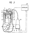
- the fuel injection control apparatus of this heat-insulating engine with swirl chamber includes one nozzle 27 for supplying the fuel to the swirl chamber 4 and the fuel pressurization pump 28 for supplying the fuel to the nozzle 27.
- This nozzle 27 has the same structure as that of the subsidiary nozzle 2 described above and includes an accumulation chamber for accumulating temporarily the fuel feed pressure and a needle valve opened and closed electrically.
- the fuel injection control apparatus is also equipped with a sensor 24 for detecting an engine load as one of the operating conditions of the engine, a sensor 25 for detecting the engine revolution as another operating condition of the engine and a controller 20 for receiving the detection signals of these sensors 24, 25 and generating the instruction to the nozzle 27.
- the controller 20 controls the flow rate of the fuel injected from the nozzle 27 into the swirl chamber in response to the detection signals from the sensors 24, 25 and controls the opening and open timing of the nozzle 27 so that the fuel can be injected mainly into the swirl chambers 4 from the second half of the compression stroke to the expansion stroke and subsidiarily into the swirl chambers 4 from the second half of the intake stroke to the compression stroke. Accordingly, the fuel injection control apparatus of this heat-insulating engine with swirl chamber can make main injection and subsidiary injection into the swirl chambers by having only the nozzle 27 and the fuel pressurization pump 28.
Applications Claiming Priority (2)
| Application Number | Priority Date | Filing Date | Title |
|---|---|---|---|
| JP1252272A JPH07116942B2 (ja) | 1989-09-29 | 1989-09-29 | 副室式断熱エンジン及びその燃料噴射制御装置 |
| JP252272/89 | 1989-09-29 |
Publications (2)
| Publication Number | Publication Date |
|---|---|
| EP0420641A1 true EP0420641A1 (de) | 1991-04-03 |
| EP0420641B1 EP0420641B1 (de) | 1993-11-24 |
Family
ID=17234934
Family Applications (1)
| Application Number | Title | Priority Date | Filing Date |
|---|---|---|---|
| EP90310594A Expired - Lifetime EP0420641B1 (de) | 1989-09-29 | 1990-09-27 | Wärmeisolierter Motor mit Wirbelkammer |
Country Status (4)
| Country | Link |
|---|---|
| US (1) | US5081970A (de) |
| EP (1) | EP0420641B1 (de) |
| JP (1) | JPH07116942B2 (de) |
| DE (2) | DE420641T1 (de) |
Cited By (1)
| Publication number | Priority date | Publication date | Assignee | Title |
|---|---|---|---|---|
| EP3885565A4 (de) * | 2018-11-20 | 2022-08-10 | Yanmar Power Technology Co., Ltd. | Unterkammer-dieselmotor |
Families Citing this family (8)
| Publication number | Priority date | Publication date | Assignee | Title |
|---|---|---|---|---|
| DE4138290A1 (de) * | 1991-11-21 | 1993-05-27 | Kloeckner Humboldt Deutz Ag | Brennkraftmaschine |
| JPH08135462A (ja) * | 1994-11-09 | 1996-05-28 | Yamaha Motor Co Ltd | 縦型エンジン |
| US5522218A (en) * | 1994-08-23 | 1996-06-04 | Caterpillar Inc. | Combustion exhaust purification system and method |
| US5727519A (en) * | 1996-05-24 | 1998-03-17 | Isuzu Ceramics Research Institute Co., Ltd. | Low evaporativity fuel diesel engine |
| EP1502024B1 (de) * | 2002-05-03 | 2007-07-04 | Siemens Aktiengesellschaft | Kraftstoffeinspritzventil mit mechanischer zwangssteuerung |
| FR2914962B1 (fr) * | 2007-04-10 | 2012-07-06 | Univ Paris Curie | Procede d'initiation de la combustion dans un moteur a combustion interne, et moteur faisant application |
| US9453456B2 (en) * | 2014-01-21 | 2016-09-27 | Dresser-Rand Company | Electronic pre-chamber injector |
| JP7445099B2 (ja) * | 2021-12-10 | 2024-03-07 | 株式会社クボタ | ディーゼルエンジン |
Citations (3)
| Publication number | Priority date | Publication date | Assignee | Title |
|---|---|---|---|---|
| DE2922683A1 (de) * | 1979-06-02 | 1980-12-04 | Daimler Benz Ag | Luftverdichtende selbstzuendende brennkraftmaschine |
| DE3442628A1 (de) * | 1984-11-22 | 1986-05-22 | Michael Dipl.-Ing. 8000 München Simon | Schadstoffarmer integral-verbrennungsmotor mit dualtreibstoffzufuhr |
| EP0352058A2 (de) * | 1988-07-21 | 1990-01-24 | Isuzu Motors Limited | Wärmeisolierte Brennkraftmaschine |
Family Cites Families (6)
| Publication number | Priority date | Publication date | Assignee | Title |
|---|---|---|---|---|
| US2594681A (en) * | 1947-03-07 | 1952-04-29 | Ricardo & Co Engineers | Internal-combustion engine |
| US2858814A (en) * | 1957-07-29 | 1958-11-04 | Maschf Augsburg Nuernberg Ag | Fuel injection engine |
| JPS5438439A (en) * | 1977-08-30 | 1979-03-23 | Agency Of Ind Science & Technol | Fuel injection for pump multiple injection |
| JPS58151356U (ja) * | 1982-04-05 | 1983-10-11 | 三菱重工業株式会社 | 二元燃料デイ−ゼルエンジン |
| JPS59123620U (ja) * | 1983-02-10 | 1984-08-20 | マツダ株式会社 | 渦流室式デイ−ゼルエンジンの燃料噴射制御装置 |
| JPS6238828A (ja) * | 1985-08-13 | 1987-02-19 | Isuzu Motors Ltd | 直噴式デイ−ゼル機関 |
-
1989
- 1989-09-29 JP JP1252272A patent/JPH07116942B2/ja not_active Expired - Lifetime
-
1990
- 1990-09-27 EP EP90310594A patent/EP0420641B1/de not_active Expired - Lifetime
- 1990-09-27 DE DE199090310594T patent/DE420641T1/de active Pending
- 1990-09-27 DE DE69004771T patent/DE69004771T2/de not_active Expired - Fee Related
- 1990-10-01 US US07/591,168 patent/US5081970A/en not_active Expired - Fee Related
Patent Citations (3)
| Publication number | Priority date | Publication date | Assignee | Title |
|---|---|---|---|---|
| DE2922683A1 (de) * | 1979-06-02 | 1980-12-04 | Daimler Benz Ag | Luftverdichtende selbstzuendende brennkraftmaschine |
| DE3442628A1 (de) * | 1984-11-22 | 1986-05-22 | Michael Dipl.-Ing. 8000 München Simon | Schadstoffarmer integral-verbrennungsmotor mit dualtreibstoffzufuhr |
| EP0352058A2 (de) * | 1988-07-21 | 1990-01-24 | Isuzu Motors Limited | Wärmeisolierte Brennkraftmaschine |
Non-Patent Citations (2)
| Title |
|---|
| PATENT ABSTRACTS OF JAPAN vol. 10, no. 44 (M-455)(2101) 21 February 1986, & JP-A-60 195373 (ISUZU JIDOSHA K.K.) * |
| PATENT ABSTRACTS OF JAPAN vol. 6, no. 109 (M-137)(987) 19 June 1982, & JP-A-57 38614 (NIPPON JIDOUSHIYA KENKYUSHO) * |
Cited By (1)
| Publication number | Priority date | Publication date | Assignee | Title |
|---|---|---|---|---|
| EP3885565A4 (de) * | 2018-11-20 | 2022-08-10 | Yanmar Power Technology Co., Ltd. | Unterkammer-dieselmotor |
Also Published As
| Publication number | Publication date |
|---|---|
| JPH03115724A (ja) | 1991-05-16 |
| DE69004771T2 (de) | 1994-05-19 |
| US5081970A (en) | 1992-01-21 |
| DE420641T1 (de) | 1991-10-17 |
| DE69004771D1 (de) | 1994-01-05 |
| JPH07116942B2 (ja) | 1995-12-18 |
| EP0420641B1 (de) | 1993-11-24 |
Similar Documents
| Publication | Publication Date | Title |
|---|---|---|
| US6209516B1 (en) | Control system and control method for diesel engine | |
| US5020504A (en) | Fuel injection control system for a two-cycle engine | |
| US5119780A (en) | Staged direct injection diesel engine | |
| US5724927A (en) | Direct cylinder injected engine and method of operating same | |
| US6536407B1 (en) | Method of controlling the process of combustion in an internal combustion engine, and engine with means for controlling the engine valves | |
| US5190006A (en) | Injection arrangement for improving fuel consumption | |
| US4210105A (en) | Internal combustion engine injected accumulation chamber | |
| EP0980969A2 (de) | Betriebsverfahren für eine Zweitaktbrennkraftmaschine mit Direkteinspritzung und diese Brennkraftmaschine | |
| KR19990063947A (ko) | 내연기관의 제어장치 | |
| KR100679065B1 (ko) | 내연기관의 연소과정을 제어하는 방법 및 실린더의 유효압축비를 변화시키기 위한 수단을 구비한 엔진 | |
| US5083533A (en) | Two-stroke-cycle engine with variable valve timing | |
| US5081970A (en) | Heat-insulating engine with swirl chamber | |
| US5203298A (en) | Pre-combustion chamber for internal combustion engine | |
| US4237826A (en) | Multi-cylinder internal combustion engine equipped with an accumulation chamber | |
| US5080081A (en) | Four-cycle heat insulating engine | |
| EP0420456B1 (de) | Motor mit wärmeisolierter Wirbelkammer | |
| US5189996A (en) | Two-stroke-cycle engine with variable valve timing | |
| JP2946729B2 (ja) | 排気ガス再循環装置を備えた副室式エンジン | |
| JPH03115730A (ja) | 断熱エンジン及びその作動制御装置 | |
| JPH0791271A (ja) | 直接噴射燃焼エンジンとこのエンジンの駆動方法 | |
| US5148778A (en) | Combustion chamber for a self-igniting or spark-ignited valveless two-stroke internal combustion engine | |
| JPH06200832A (ja) | 2ストロークエンジン | |
| WO1999007984A1 (en) | Internal combustion engines | |
| JPH03115725A (ja) | 副室式断熱エンジンの燃料噴射装置 | |
| JP2730198B2 (ja) | 4サイクル断熱エンジン |
Legal Events
| Date | Code | Title | Description |
|---|---|---|---|
| PUAI | Public reference made under article 153(3) epc to a published international application that has entered the european phase |
Free format text: ORIGINAL CODE: 0009012 |
|
| AK | Designated contracting states |
Kind code of ref document: A1 Designated state(s): DE GB |
|
| 17P | Request for examination filed |
Effective date: 19910426 |
|
| DET | De: translation of patent claims | ||
| 17Q | First examination report despatched |
Effective date: 19910904 |
|
| GRAA | (expected) grant |
Free format text: ORIGINAL CODE: 0009210 |
|
| AK | Designated contracting states |
Kind code of ref document: B1 Designated state(s): DE GB |
|
| REF | Corresponds to: |
Ref document number: 69004771 Country of ref document: DE Date of ref document: 19940105 |
|
| PLBE | No opposition filed within time limit |
Free format text: ORIGINAL CODE: 0009261 |
|
| STAA | Information on the status of an ep patent application or granted ep patent |
Free format text: STATUS: NO OPPOSITION FILED WITHIN TIME LIMIT |
|
| 26N | No opposition filed | ||
| PGFP | Annual fee paid to national office [announced via postgrant information from national office to epo] |
Ref country code: GB Payment date: 19950918 Year of fee payment: 6 |
|
| PGFP | Annual fee paid to national office [announced via postgrant information from national office to epo] |
Ref country code: DE Payment date: 19951026 Year of fee payment: 6 |
|
| PG25 | Lapsed in a contracting state [announced via postgrant information from national office to epo] |
Ref country code: GB Effective date: 19960927 |
|
| GBPC | Gb: european patent ceased through non-payment of renewal fee |
Effective date: 19960927 |
|
| PG25 | Lapsed in a contracting state [announced via postgrant information from national office to epo] |
Ref country code: DE Effective date: 19970603 |