EP0419656A1 - Regulateur de vitesse - Google Patents
Regulateur de vitesse Download PDFInfo
- Publication number
- EP0419656A1 EP0419656A1 EP89901746A EP89901746A EP0419656A1 EP 0419656 A1 EP0419656 A1 EP 0419656A1 EP 89901746 A EP89901746 A EP 89901746A EP 89901746 A EP89901746 A EP 89901746A EP 0419656 A1 EP0419656 A1 EP 0419656A1
- Authority
- EP
- European Patent Office
- Prior art keywords
- current
- constant
- pwm
- command
- servomotor
- Prior art date
- Legal status (The legal status is an assumption and is not a legal conclusion. Google has not performed a legal analysis and makes no representation as to the accuracy of the status listed.)
- Granted
Links
Images

Classifications
-
- H—ELECTRICITY
- H02—GENERATION; CONVERSION OR DISTRIBUTION OF ELECTRIC POWER
- H02P—CONTROL OR REGULATION OF ELECTRIC MOTORS, ELECTRIC GENERATORS OR DYNAMO-ELECTRIC CONVERTERS; CONTROLLING TRANSFORMERS, REACTORS OR CHOKE COILS
- H02P27/00—Arrangements or methods for the control of AC motors characterised by the kind of supply voltage
- H02P27/04—Arrangements or methods for the control of AC motors characterised by the kind of supply voltage using variable-frequency supply voltage, e.g. inverter or converter supply voltage
- H02P27/06—Arrangements or methods for the control of AC motors characterised by the kind of supply voltage using variable-frequency supply voltage, e.g. inverter or converter supply voltage using dc to ac converters or inverters
- H02P27/08—Arrangements or methods for the control of AC motors characterised by the kind of supply voltage using variable-frequency supply voltage, e.g. inverter or converter supply voltage using dc to ac converters or inverters with pulse width modulation
-
- G—PHYSICS
- G05—CONTROLLING; REGULATING
- G05B—CONTROL OR REGULATING SYSTEMS IN GENERAL; FUNCTIONAL ELEMENTS OF SUCH SYSTEMS; MONITORING OR TESTING ARRANGEMENTS FOR SUCH SYSTEMS OR ELEMENTS
- G05B11/00—Automatic controllers
- G05B11/01—Automatic controllers electric
- G05B11/26—Automatic controllers electric in which the output signal is a pulse-train
- G05B11/28—Automatic controllers electric in which the output signal is a pulse-train using pulse-height modulation; using pulse-width modulation
-
- H—ELECTRICITY
- H02—GENERATION; CONVERSION OR DISTRIBUTION OF ELECTRIC POWER
- H02M—APPARATUS FOR CONVERSION BETWEEN AC AND AC, BETWEEN AC AND DC, OR BETWEEN DC AND DC, AND FOR USE WITH MAINS OR SIMILAR POWER SUPPLY SYSTEMS; CONVERSION OF DC OR AC INPUT POWER INTO SURGE OUTPUT POWER; CONTROL OR REGULATION THEREOF
- H02M5/00—Conversion of ac power input into ac power output, e.g. for change of voltage, for change of frequency, for change of number of phases
- H02M5/40—Conversion of ac power input into ac power output, e.g. for change of voltage, for change of frequency, for change of number of phases with intermediate conversion into dc
- H02M5/42—Conversion of ac power input into ac power output, e.g. for change of voltage, for change of frequency, for change of number of phases with intermediate conversion into dc by static converters
- H02M5/44—Conversion of ac power input into ac power output, e.g. for change of voltage, for change of frequency, for change of number of phases with intermediate conversion into dc by static converters using discharge tubes or semiconductor devices to convert the intermediate dc into ac
- H02M5/453—Conversion of ac power input into ac power output, e.g. for change of voltage, for change of frequency, for change of number of phases with intermediate conversion into dc by static converters using discharge tubes or semiconductor devices to convert the intermediate dc into ac using devices of a triode or transistor type requiring continuous application of a control signal
- H02M5/458—Conversion of ac power input into ac power output, e.g. for change of voltage, for change of frequency, for change of number of phases with intermediate conversion into dc by static converters using discharge tubes or semiconductor devices to convert the intermediate dc into ac using devices of a triode or transistor type requiring continuous application of a control signal using semiconductor devices only
Definitions
- This invention relates to a velocity control apparatus for controlling the velocity of a servomotor by PWM (pulse-width modulation) control of an inverter.
- PWM pulse-width modulation
- microprocessors have come to be widely used in velocity control apparatus for controlling motor drive.
- table information such as amplitude characteristics decided in conformity with motor characteristics is created, and the velocity of a servomotor is controlled by PWM control of an inverter based on a set velocity signal.
- the range of fluctuation allowed with regard to power supply voltage is set to be within a prescribed limit.
- the apparatus is provided with a function which protects the motor from overcurrents when the aforementioned limit is exceeded, and with a protective function which shuts down the system automatically when the voltage is too low.
- no particular consideration is given to fluctuations within the prescribed limit.
- the present invention has been devised to solve the foregoing problems and its object is to provide a velocity control apparatus which makes stable velocity control possible by compensating for fluctuation in power supply voltage and obtaining a constant current loop gain.
- a velocity control apparatus for controlling the drive current of a servomotor by a PWM-controlled inverter circuit, thereby controlling velocity of the servomotor, the apparatus being characterized by comprising a power supply of the inverter circuit, voltage detecting means for detecting an output voltage value of the power supply, and gain control means for holding constant current loop gain based on the detected voltage value.
- a PWM control device for PWM-controlling the inverter circuit used in the velocity control apparatus, the device characterized by comprising constant computing means for computing a current loop constant inversely proportional to the power supply voltage of the inverter circuit, and signal generating means for forming a PWM control signal from the current loop constant and a command current value in such a manner that the current loop gain becomes constant.
- the power supply voltage is detected at all times and the current loop gain is held constant to enhance the stability of the control system.
- the PWM control device of the invention it is possible to construct a control system stabilized with respect to fluctuations in power supply voltage.
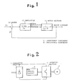
- Fig. l is a block diagram illustrating an embodiment of the present invention
- Fig. 2 is a view illustrating an example of the construction of a motor control system
- Fig. 3 is a time chart for describing PWM control
- Fig. 4 is a view for describing computation with regard to current loop gain K'
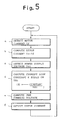
- Fig. 5 is a flowchart illustrating a processing procedure for setting gain.
- Fig. 2 is a view illustrating an example of the construction of a PWM-controlled motor control system.
- An inverter section 2 supplied with commercial AC voltage is connected to a converter section l as a DC power supply having a predetermined voltage value.
- the inverter section 2 is a transistorized inverter comprising a plurality of switching transistors and is for driving a three-phase AC motor 3.
- the inverter section 2 is connected to a PWM control circuit 4 and controls a current supplied to the primary side of the motor 3 in response to a PWM control signal applied to the base of each transistor from the PWM control circuit 4.
- the motor can thus be controlled to vary its velocity.
- Fig. 3 is a time chart for describing PWM control of the transistors in the inverter section 2 by means of the PWM control circuit 4.
- a triangular wave having a period of 2T is supplied as a carrier wave, and on time T on of the transistors in the inverter section 2 is decided by comparing the triangular wave with the level of a PWM command voltage E. Note that + Pa represents the amplitude of the carrier wave.
- command voltage E is inputted as K(Ic-If) with respect to a current loop constant K, and on time of the transistors, namely the value of drive current applied to the motor 3, is decided in dependence upon the magnitude of the command voltage E.
- Ic is a command current value decided by a torque command value, and If is a current feedback signal from the motor 3.
- Fig. l is a block diagram illustrating the current loop of the motor current controlled by the command current value I c .
- the command current Ic is compared with the current feedback signal lf from the motor 3 by an adder l which computes a current error.
- the value of the error current is outputted by a current feedback loop which includes an amplifier ll having a current loop gain K' capable of variably setting the current loop gain constant K, and a motor section l2 having an electrical constant K".
- the current loop constant K is set in such a manner that the current loop gain K' will be constant irrespective of a fluctuation in power supply voltage.
- Fig. 5 is a flowchart illustrating a processing procedure for setting gain in the abovementioned motor current control loop.
- the motor current is sampled and detected as a digital value in a prescribed interval (step a).
- the current error Ic - If is calculated based on the current value If (step b).
- the power supply voltage Vdc supplied to the inverter section 2 also is detected (step c).
- the current loop constant K is calculated using this detected power supply voltage Vc (step d), and the PWM control signal is calculated from the current error and current loop constant in such a manner that the current loop gain will be rendered constant (step e).
- the motor current is decided by the PWM control signal thus outputted, and velocity control is carried out (step f).
- the velocity control apparatus of the present invention is capable of rendering current loop gain constant by setting a current loop constant that is inversely proportional to a fluctuation in power supply voltage. This makes possible stabilized velocity control of a servomotor.
Landscapes
- Engineering & Computer Science (AREA)
- Power Engineering (AREA)
- Physics & Mathematics (AREA)
- General Physics & Mathematics (AREA)
- Automation & Control Theory (AREA)
- Control Of Ac Motors In General (AREA)
- Inverter Devices (AREA)
Abstract
Applications Claiming Priority (3)
| Application Number | Priority Date | Filing Date | Title |
|---|---|---|---|
| JP17441/88 | 1988-01-29 | ||
| JP63017441A JP2873689B2 (ja) | 1988-01-29 | 1988-01-29 | 速度制御装置 |
| PCT/JP1989/000083 WO1989007364A1 (fr) | 1988-01-29 | 1989-01-27 | Regulateur de vitesse |
Publications (3)
| Publication Number | Publication Date |
|---|---|
| EP0419656A1 true EP0419656A1 (fr) | 1991-04-03 |
| EP0419656A4 EP0419656A4 (en) | 1992-01-15 |
| EP0419656B1 EP0419656B1 (fr) | 1995-03-22 |
Family
ID=11944112
Family Applications (1)
| Application Number | Title | Priority Date | Filing Date |
|---|---|---|---|
| EP89901746A Expired - Lifetime EP0419656B1 (fr) | 1988-01-29 | 1989-01-27 | Regulateur de vitesse |
Country Status (6)
| Country | Link |
|---|---|
| US (1) | US5132599A (fr) |
| EP (1) | EP0419656B1 (fr) |
| JP (1) | JP2873689B2 (fr) |
| KR (1) | KR940011385B1 (fr) |
| DE (1) | DE68921887T2 (fr) |
| WO (1) | WO1989007364A1 (fr) |
Cited By (3)
| Publication number | Priority date | Publication date | Assignee | Title |
|---|---|---|---|---|
| EP0909016A2 (fr) * | 1997-10-08 | 1999-04-14 | Tamagawa Seiki Kabushiki Kaisha | Procédé de commande d'un servomoteur |
| EP1085225A2 (fr) * | 1999-09-13 | 2001-03-21 | Ebara Corporation | Palier magnétique pour structure combinée de moteur |
| GB2391076B (en) * | 2002-05-28 | 2005-10-12 | Toshiba Machine Co Ltd | Servo control device |
Families Citing this family (15)
| Publication number | Priority date | Publication date | Assignee | Title |
|---|---|---|---|---|
| JP2873689B2 (ja) * | 1988-01-29 | 1999-03-24 | ファナック株式会社 | 速度制御装置 |
| US5517099A (en) * | 1993-06-15 | 1996-05-14 | International Modern Technologies, Inc. | Method and apparatus for robust integral-pulse control of a servodrive of unknown dynamics |
| US5767653A (en) * | 1995-10-24 | 1998-06-16 | Micro Linear Corporation | Variable speed AC induction motor controller |
| ES2114466B1 (es) * | 1995-11-23 | 1999-02-01 | Saf Nife Iberica S A | Metodo para obtener una tension eficaz constante a partir de una tension continua variable. |
| US5714897A (en) * | 1996-06-19 | 1998-02-03 | Micro Linear Corporation | Phase-shifted triangle wave generator |
| US5793168A (en) * | 1996-08-23 | 1998-08-11 | Micro Linear Corporation | Active deceleration circuit for a brushless DC motor |
| JP3652084B2 (ja) * | 1997-10-08 | 2005-05-25 | 多摩川精機株式会社 | サーボモータ駆動方法 |
| US5859518A (en) * | 1997-12-22 | 1999-01-12 | Micro Linear Corporation | Switched reluctance motor controller with sensorless rotor position detection |
| US6974536B2 (en) | 1999-05-10 | 2005-12-13 | Chaffee Kevin R | Wastewater treatment apparatus including dosing and recirculation chambers within a single tank |
| US20070068856A1 (en) * | 1999-05-10 | 2007-03-29 | Chaffee Kevin R | Wastewater treatment apparatus |
| US20020004774A1 (en) * | 2000-03-27 | 2002-01-10 | Tony Defarlo | Data analysis system for tracking financial trader history and profiling trading behavior |
| US20040265061A1 (en) * | 2003-04-16 | 2004-12-30 | Chaffee Kevin R. | Subsurface wastewater infiltration system |
| US20080135472A1 (en) * | 2004-08-19 | 2008-06-12 | Chaffee Kevin R | Trickling Filter Wastewater Treatment Device |
| US7662277B1 (en) | 2005-04-29 | 2010-02-16 | Kevin R Chaffee | Wastewater treatment apparatus |
| JP5681470B2 (ja) * | 2010-12-13 | 2015-03-11 | 川崎重工業株式会社 | サーボアンプの制御ループゲイン調整方法、プログラム及びロボット制御装置 |
Citations (3)
| Publication number | Priority date | Publication date | Assignee | Title |
|---|---|---|---|---|
| JPS60197189A (ja) * | 1984-03-19 | 1985-10-05 | Nissan Motor Co Ltd | 交流モ−タの制御装置 |
| DE3527844A1 (de) * | 1985-07-31 | 1987-02-12 | Licentia Gmbh | Schaltungsanordnung zur frequenzverstellung eines gleichspannungs-zwischenkreisumrichters bei konstanter ausgangsspannung |
| WO1989007364A1 (fr) * | 1988-01-29 | 1989-08-10 | Fanuc Ltd | Regulateur de vitesse |
Family Cites Families (19)
| Publication number | Priority date | Publication date | Assignee | Title |
|---|---|---|---|---|
| US4088934A (en) * | 1976-10-04 | 1978-05-09 | General Electric Company | Means for stabilizing an a-c electric motor drive system |
| US4295081A (en) * | 1978-01-06 | 1981-10-13 | Lockheed Electronics Co., Inc. | Load actuating servomechanism with resonance equalization |
| US4227138A (en) * | 1978-04-10 | 1980-10-07 | General Electric Company | Reversible variable frequency oscillator for smooth reversing of AC motor drives |
| US4274042A (en) * | 1979-04-24 | 1981-06-16 | General Electric Company | AC Motor drive system having clamped command error signal |
| US4320331A (en) * | 1979-10-01 | 1982-03-16 | General Electric Company | Transistorized current controlled pulse width modulated inverter machine drive system |
| US4467262A (en) * | 1980-03-24 | 1984-08-21 | The Charles Stark Draper Laboratory, Inc. | Polyphase motor drive system with balanced modulation |
| US4314190A (en) * | 1980-04-22 | 1982-02-02 | General Electric Company | Controlled current inverter with angle command limit |
| US4461988A (en) * | 1981-04-06 | 1984-07-24 | General Electric Company | Apparatus for controlling an electrical vehicle drive system |
| JPS5886888A (ja) * | 1981-11-16 | 1983-05-24 | Hitachi Ltd | 誘導電動機の制御方式 |
| US4418308A (en) * | 1982-08-09 | 1983-11-29 | General Electric Company | Scalar decoupled control for an induction machine |
| JPS59142603A (ja) * | 1983-02-01 | 1984-08-15 | Sanyo Denki Kk | 高ゲインフイ−ドバツク制御系 |
| EP0117558B1 (fr) * | 1983-02-28 | 1988-08-24 | Hitachi, Ltd. | Procédé et appareil pour le contrôle d'un onduleur travaillant en modulation de largeur d'impulsion |
| JPS61240875A (ja) * | 1985-04-16 | 1986-10-27 | Fanuc Ltd | 三相誘導電動機の制御方法 |
| JPS61254093A (ja) * | 1985-04-30 | 1986-11-11 | Mitsubishi Electric Corp | 誘導電動機の制御装置 |
| JPS6240083A (ja) * | 1985-08-14 | 1987-02-21 | Fanuc Ltd | 三相誘導電動機の制御方法 |
| GB2186133B (en) * | 1985-12-27 | 1989-11-15 | Mitsubishi Electric Corp | Inverter |
| JPH0736702B2 (ja) * | 1986-02-28 | 1995-04-19 | 三菱電機株式会社 | インバ−タ装置の制御回路 |
| US4904919A (en) * | 1988-06-21 | 1990-02-27 | Allen-Bradley Company, Inc. | Dual mode control of a PWM motor drive for current limiting |
| JPH0682078A (ja) * | 1992-09-02 | 1994-03-22 | Sanden Corp | エアコンの制御装置 |
-
1988
- 1988-01-29 JP JP63017441A patent/JP2873689B2/ja not_active Expired - Fee Related
-
1989
- 1989-01-27 EP EP89901746A patent/EP0419656B1/fr not_active Expired - Lifetime
- 1989-01-27 KR KR1019890701757A patent/KR940011385B1/ko not_active IP Right Cessation
- 1989-01-27 DE DE68921887T patent/DE68921887T2/de not_active Expired - Fee Related
- 1989-01-27 WO PCT/JP1989/000083 patent/WO1989007364A1/fr active IP Right Grant
- 1989-01-27 US US07/415,240 patent/US5132599A/en not_active Expired - Lifetime
Patent Citations (3)
| Publication number | Priority date | Publication date | Assignee | Title |
|---|---|---|---|---|
| JPS60197189A (ja) * | 1984-03-19 | 1985-10-05 | Nissan Motor Co Ltd | 交流モ−タの制御装置 |
| DE3527844A1 (de) * | 1985-07-31 | 1987-02-12 | Licentia Gmbh | Schaltungsanordnung zur frequenzverstellung eines gleichspannungs-zwischenkreisumrichters bei konstanter ausgangsspannung |
| WO1989007364A1 (fr) * | 1988-01-29 | 1989-08-10 | Fanuc Ltd | Regulateur de vitesse |
Non-Patent Citations (3)
| Title |
|---|
| CONF. RECORD 1987 IEEE 23 October 1987, US P. ENJETI ET AL: 'A NEW CURRENT CONTROL SCHEME FOR AC MOTOR DRIVES' * |
| PATENT ABSTRACTS OF JAPAN vol. 10, no. 42 (E-382)(2099) 19 February 1986 & JP-A-60 197 189 ( NISSAN JIDOSHA K.K. ) 5 October 1985 * |
| See also references of WO8907364A1 * |
Cited By (8)
| Publication number | Priority date | Publication date | Assignee | Title |
|---|---|---|---|---|
| EP0909016A2 (fr) * | 1997-10-08 | 1999-04-14 | Tamagawa Seiki Kabushiki Kaisha | Procédé de commande d'un servomoteur |
| EP0909016A3 (fr) * | 1997-10-08 | 1999-09-01 | Tamagawa Seiki Kabushiki Kaisha | Procédé de commande d'un servomoteur |
| US6025684A (en) * | 1997-10-08 | 2000-02-15 | Tamagawa Seiki Kabushiki Kaisha | Servo-motor driving method |
| EP1085225A2 (fr) * | 1999-09-13 | 2001-03-21 | Ebara Corporation | Palier magnétique pour structure combinée de moteur |
| EP1085225A3 (fr) * | 1999-09-13 | 2003-04-23 | Ebara Corporation | Palier magnétique pour structure combinée de moteur |
| GB2391076B (en) * | 2002-05-28 | 2005-10-12 | Toshiba Machine Co Ltd | Servo control device |
| US7002315B2 (en) | 2002-05-28 | 2006-02-21 | Toshiba Kikai Kabushiki Kaisha | Servo control device |
| US7541763B2 (en) | 2002-05-28 | 2009-06-02 | Toshiba Kikai Kabushiki Kaisha | Servo control device |
Also Published As
| Publication number | Publication date |
|---|---|
| JP2873689B2 (ja) | 1999-03-24 |
| KR900701089A (ko) | 1990-08-17 |
| WO1989007364A1 (fr) | 1989-08-10 |
| DE68921887D1 (de) | 1995-04-27 |
| JPH01194890A (ja) | 1989-08-04 |
| EP0419656B1 (fr) | 1995-03-22 |
| DE68921887T2 (de) | 1995-07-20 |
| KR940011385B1 (ko) | 1994-12-07 |
| US5132599A (en) | 1992-07-21 |
| EP0419656A4 (en) | 1992-01-15 |
Similar Documents
| Publication | Publication Date | Title |
|---|---|---|
| EP0419656B1 (fr) | Regulateur de vitesse | |
| US5686807A (en) | Torque control system for AC motor | |
| EP0102614B1 (fr) | Méthode et appareil pour commander un inverteur à impulsion modulée en largeur | |
| KR890013871A (ko) | 유도 모터 벡터 제어방법 및 장치 | |
| US4683412A (en) | Current source inverter motor drive adapted for full current regenerative mode operation | |
| US5386186A (en) | Stator flux oriented control | |
| US4694236A (en) | Control for AC motor drive | |
| EP0526915B1 (fr) | Système de régulation pour commander la vitesse de rotation d'un moteur électrique | |
| ES8106642A1 (es) | Un sistema de control para un inversor conectado para pro- pulsar un motor electrico | |
| JPH0947082A (ja) | デッドタイム補正機能を有するpwmインバ−タ | |
| JP3212354B2 (ja) | 電圧形インバータ制御方法及びその装置 | |
| JP3675186B2 (ja) | 電気推進装置の制御方法 | |
| US4791346A (en) | Elevator motor control | |
| SU997215A2 (ru) | Электропривод с подчиненным регулированием параметров | |
| JPH0767311B2 (ja) | 交流電動機駆動用インバ−タ装置の電流及びトルク制限回路 | |
| JP3074687B2 (ja) | 誘導電動機の制御装置 | |
| SU802101A1 (ru) | Устройство дл регулировани НАпР жЕНи | |
| JPS61254098A (ja) | 誘導電動機の制御回路 | |
| JPH05300747A (ja) | インバータの電流制御装置 | |
| JPS6240955B2 (fr) | ||
| JPH0270284A (ja) | 誘導電動機の制御方法 | |
| JPS6412194B2 (fr) | ||
| JPH06165562A (ja) | 誘導電動機のトルク制御方法および装置 | |
| JPS62254671A (ja) | 電動機駆動用インバ−タの制御回路 | |
| JPS62141989A (ja) | 誘導電動機の制御装置 |
Legal Events
| Date | Code | Title | Description |
|---|---|---|---|
| PUAI | Public reference made under article 153(3) epc to a published international application that has entered the european phase |
Free format text: ORIGINAL CODE: 0009012 |
|
| 17P | Request for examination filed |
Effective date: 19891004 |
|
| AK | Designated contracting states |
Kind code of ref document: A1 Designated state(s): DE FR GB |
|
| A4 | Supplementary search report drawn up and despatched |
Effective date: 19911125 |
|
| AK | Designated contracting states |
Kind code of ref document: A4 Designated state(s): DE FR GB |
|
| 17Q | First examination report despatched |
Effective date: 19930419 |
|
| GRAA | (expected) grant |
Free format text: ORIGINAL CODE: 0009210 |
|
| AK | Designated contracting states |
Kind code of ref document: B1 Designated state(s): DE FR GB |
|
| PG25 | Lapsed in a contracting state [announced via postgrant information from national office to epo] |
Ref country code: FR Effective date: 19950322 |
|
| REF | Corresponds to: |
Ref document number: 68921887 Country of ref document: DE Date of ref document: 19950427 |
|
| EN | Fr: translation not filed | ||
| PLBE | No opposition filed within time limit |
Free format text: ORIGINAL CODE: 0009261 |
|
| STAA | Information on the status of an ep patent application or granted ep patent |
Free format text: STATUS: NO OPPOSITION FILED WITHIN TIME LIMIT |
|
| PG25 | Lapsed in a contracting state [announced via postgrant information from national office to epo] |
Ref country code: GB Effective date: 19960127 |
|
| 26N | No opposition filed | ||
| GBPC | Gb: european patent ceased through non-payment of renewal fee |
Effective date: 19960127 |
|
| PGFP | Annual fee paid to national office [announced via postgrant information from national office to epo] |
Ref country code: DE Payment date: 20070305 Year of fee payment: 19 |
|
| PG25 | Lapsed in a contracting state [announced via postgrant information from national office to epo] |
Ref country code: DE Free format text: LAPSE BECAUSE OF NON-PAYMENT OF DUE FEES Effective date: 20080801 |