EP0418698A1 - Borne électrique et connecteur électrique comportant une telle borne - Google Patents
Borne électrique et connecteur électrique comportant une telle borne Download PDFInfo
- Publication number
- EP0418698A1 EP0418698A1 EP90117395A EP90117395A EP0418698A1 EP 0418698 A1 EP0418698 A1 EP 0418698A1 EP 90117395 A EP90117395 A EP 90117395A EP 90117395 A EP90117395 A EP 90117395A EP 0418698 A1 EP0418698 A1 EP 0418698A1
- Authority
- EP
- European Patent Office
- Prior art keywords
- terminal
- blade
- section
- terminals
- edge portions
- Prior art date
- Legal status (The legal status is an assumption and is not a legal conclusion. Google has not performed a legal analysis and makes no representation as to the accuracy of the status listed.)
- Granted
Links
Images


Classifications
-
- H—ELECTRICITY
- H01—ELECTRIC ELEMENTS
- H01R—ELECTRICALLY-CONDUCTIVE CONNECTIONS; STRUCTURAL ASSOCIATIONS OF A PLURALITY OF MUTUALLY-INSULATED ELECTRICAL CONNECTING ELEMENTS; COUPLING DEVICES; CURRENT COLLECTORS
- H01R13/00—Details of coupling devices of the kinds covered by groups H01R12/70 or H01R24/00 - H01R33/00
- H01R13/02—Contact members
- H01R13/04—Pins or blades for co-operation with sockets
-
- H—ELECTRICITY
- H01—ELECTRIC ELEMENTS
- H01R—ELECTRICALLY-CONDUCTIVE CONNECTIONS; STRUCTURAL ASSOCIATIONS OF A PLURALITY OF MUTUALLY-INSULATED ELECTRICAL CONNECTING ELEMENTS; COUPLING DEVICES; CURRENT COLLECTORS
- H01R13/00—Details of coupling devices of the kinds covered by groups H01R12/70 or H01R24/00 - H01R33/00
- H01R13/02—Contact members
Definitions
- This invention relates to electrical connectors and more specifically to disconnectable electrical connectors comprising a blade contact matable with a receptacle contact incorporating a spring member in which each of the contact terminals is mounted in an insulative housing containing one or more of the matable terminals.
- Pin and socket electrical terminals of the type shown in U.S. Patent 4,544,220 are commonly employed to connect wires in separate electrical harnesses. These pin and socket electrical connectors are commonly employed in industries such as the appliance and automotive industries. Since pin and socket terminals are symmetrical in nature, they can be easily employed in applications where the terminals are first attached to appropriate wires in a harness and then inserted into an insulative housing having a plurality of cavities, because the operator need not orient the symmetrical terminals prior to insertion into the appropriate cavity.
- One drawback of conventional pin and socket terminals is that their symmetrical nature makes it impossible to precisely define a contact interface between the cylindrical pin and the cylindrical socket. Even if a contact point could be initially specified, that contact point would change during the life of the contact due to vibration, thermal cycling and perhaps other factors.
- disconnectable connectors employing blade and receptacle terminals such as FASTON terminals do permit establishment of a stable contact interface.
- FASTON is a trademark of AMP Incorporated.
- These disconnectable connectors employ a blade terminal which mates with a receptacle terminal having a relatively stiff spring in the form of curved sections extending laterally from the sides of the base of the receptacle terminal with the edges of the curved spring sections engaging the blade. Examples of disconnectable connectors of this type are shown in U.S. Patent 3,550,856; U.S. Patent 3,989,346; U.S. Patent 4,149,768; and U.S. patent 4,295,698.
- disconnectable receptacle terminals of the type just described, in a multiple position housing is for use in a connector which can be mated with a plurality of flat terminals in a printed circuit board header.
- An example of one such connector is shown in U.S. Patent 4,758,183.
- Another multiple position connector having this type of receptacle contact is shown in U.S. Patent 4,753,612.
- U.S. Patent 4,253,718 discloses a multiple position electrical connector in which a plurality of blade terminals attached to wires are positioned in an insulative housing. None of these patents, however, disclose wire to wire multiple position electrical connectors having matable blade and receptacle terminals mounted in matable insulative housings.
- none of these patents shows matable connector subassemblies in which multiple blade and receptacle contacts are symmetrically positioned within the housing with the mating ends of the terminals located on the centerline of the cavities in which the terminals are positioned.
- none of these patents discloses a connector in which orientation of the blade and receptacle terminals relative to the housings and to each other is unnecessary.
- An electrical connector assembly including a blade and a matable receptacle terminal also includes matable insulative housings in which the blade and receptacle are mounted. Both the blade and the receptacle terminals are centrally positioned within the housings so that orientation of the terminals is unnecessary. Both the blade and the receptacle terminals have a contact positioning section which conforms to the contour of the housing in which the respective terminal is positioned. In the preferred embodiment, this contact positioning section is rectangular to form a box section with a centrally disposed flat blade extending from the rectangular contact positioning section in one terminal and a spring receptacle extending from the rectangular contact positioning section in the other terminal.
- the blade terminal is characterized in that the blade is formed by folding edge portions of a flat blank to form a dual thickness blade.
- the edge portions are juxtaposed when folded over at least one flap.
- Each flap initially comprises an integral section of the flat blank outboard of the edge portions of the blade.
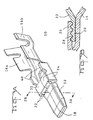
- the preferred embodiment of the electrical connector assembly 2 depicted herein comprises intermatable insulative housings 4 and 6, each containing a plurality of terminals.
- Receptacle terminals 8 are positioned within contact receiving cavities 70 in insulative housing 6, and blade terminals 10 are positioned within contact receiving cavities 60 in insulative housing 4.
- Each of the insulative housings is fabricated from a conventional plastic material of the type commonly used for electrical connector housings.
- the terminals are fabricated from conventional spring metal of the type commonly used in electrical terminals.
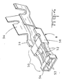
- FIGs 2 and 3 depict the details of the stamped and formed blade terminal 10.
- These terminals 10 include a blade section 12 on the mating end 18 integral with a wire contact or crimp section 16 of conventional construction.
- Crimp section 16 includes a conventional wire crimp portion 16a and a conventional insulation crimp section 16b.
- a box section 30 is located between the blade 12 and the crimp section 16.
- This blade terminal 10 is fabricated by forming or folding the flat blank 42 shown in Figure 7.
- the blade 12 is formed by folding edge portions 34 of the flat blank 42 to form a dual thickness blade. These edge portions 34 are juxtaposed edge to edge when folded over flaps 20 which extend longitudinally relative to the axis of the terminal 10.
- Blade 12 comprises an inwardly formed integral extension of one side, or a base section 36, of a rectangular contact positioning section or box section 30. Blade 12 is disposed to extend from the center of the rectangular box section 30 between the flaps 20 and the base section 36. Blade 12 is secured to the top of the contact positioning box section above the base section 36 by flaps 20. An upwardly inclined blade root section 14 extends from the base section 36 toward the flap 20. A downwardly inclined flap root section 22 is adjacent the blade 12 and is inclined from the top of the box section 30 toward the blade 12. Blade 12 is therefore centrally disposed to the top and the bottom of the rectangular box section 30.
- Flaps 20 initially comprise integral sections of the flat blank 42 outboard of edge sections 34. These longitudinally extending flaps are joined to the remainder of the flat blank 42 by integral lateral sections 24, which in combination with the flaps 20 form L-shaped sections of the flat blank 42.
- the two flaps 20 extend from the top of the box section 30 to anchor or secure the blade 12 in position centrally between the top and bottom of the box section 30.
- each flap 20 is joined to the blade 12 by interfitting tongues 26 and grooves 28.
- Alternating tongues and grooves 26, 28 are formed on the upper surface of the edge portions 34 of the flat blank 42 as shown in Figure 7A.
- Complementary tongues and grooves 26, 28 are formed on the lower surface of flaps 20 of the flat blank 42 as shown in Figure 7B. In the preferred embodiment, tongues and grooves 26, 28 are skived on the upper and lower surfaces of the flat blank 42.
- the dual thickness blade 12 if formed from the flat blank 42 by folding lateral sections 24 upwardly from the flat blank 42 into the form of a rectangular box 30 from which the flaps 20 extend toward the mating end 18 of terminal 10.
- the flaps 20 are parallel to the base portion 36 of the box section 30 and will be centrally located relative to the top and bottom of box section 30 because of the inclined flap root section 22.
- the edge portions 34 are next folded up from the central section 32 on the front of the flat blank 42 to form the dual thickness blade. Edge portions 34 are folded over the flaps 20 and the interfitting tongues and grooves 26 and 28 engage to anchor the blade 12 centrally relative to the box section 30.
- Box section 30 located between the two ends of the blade terminal 10 has blade 12 extending form the front end toward the mating end 18 of the terminal 10 and the wire contact section extending from the other end toward the rear of the terminal 10.
- the rectangular box section 30 is formed by folding up lateral sections 20 to form the folded up portions of the box section 30.
- folded up portions 24 comprise the top and sides of the box section 30 and are integral with the base portion 36, and in the preferred embodiment, these folded up portions abut on the top of the box section 30.
- a hole or contact retention opening 38 is stamped in the base section 36.
- the flaps 20 which extend from the front of the box section are received between the folded edge portions 34 and the central section 32 of blade 12.
- the box section 30 comprises a contact positioning section stabilizing the terminal 10 in the contact receiving cavity 60.
- a pair of stabilizing ribs 40 extending upwardly from the terminal base, are located between the box section 30 and the crimp section 16.
- the height of these stabilizing ribs 40 is the same as the height of the box section 30 and the stabilizing ribs 40 comprise additional stabilization means holding the terminals in place within respective cavities.
- Box section 30 is located in front of the stabilizing ribs 40 and together they prevent terminal 10 form pitching relative to the housing.
- the receptacle terminal 8 also comprises a stamped and formed terminal, preferably, though not necessarily, fabricated from the same material as the blade terminal 10.
- Receptacle terminal 8 has a receptacle section 50 extending from a contact positioning section 58 extending between a crimp section 56 and the receptacle section 50.
- the contact positioning section 58 comprises a rectangular box section of somewhat similar construction to the box section 30 in blade terminal 10.
- the receptacle section 50 comprises a spring members in the form of inwardly curved sections 52 extending from the rectangular contact positioning section 58 to a strap 54 located at the forward or mating end of terminal 8.
- the strap section 54 has substantially the same dimensions as the contact positioning section 58.
- Receptacle section 50, including strap 54 thus comprises a folded section generally corresponding to the periphery of the contact positioning section 58 which also comprises a folded up section.
- Insulative housings 4 and 6 have a plurality of cavities 60 and 70 respectively extending from rear faces to intermatable mating faces 62 and 72.
- Housing 4 comprises a female housing and housing 6 comprises a matable male housing.
- the housing 4 has three cavities 60 receiving blade terminals 10.
- the male housing 6 also has three cavities 70 receiving receptacle terminals 8.
- Each of the cavities 60 and 70 has a generally rectangular cross section conforming generally to the rectangular contact positioning sections 30 and 58 of terminals 10 and 8 respectively.
- Apertures 64 and 74 are located on the mating faces 62 and 72 respectively. These apertures are each dimensioned so that the blade 12 on terminal 10 can extend through the aperture for mating with receptacle section 50 of terminal 8.
- Each cavity 60 has stabilizing ledges 66 located on each side. Similar stabilizing ledges 76 are located in cavities 70. These ledges support the sides of the rectangular contact stabilization sections 30 and 58 and form a portion of the top of the generally rectangular shape of each cavity.
- Each housing includes and integral resilient latch 80 located on the bottom of each cavity. This latch 80 forms the bottom of the generally rectangular cavity. Latch 80 includes a latching finger located between the stabilizing ledges 66, 76 located on the opposite wall of the corresponding cavity.
- Resilient latches 80 are of conventional construction and are partially molded by a core pin extending through the apertures 64, 74 located in the mating faces of the housings.
- Each resilient latch 80 will deflect when a terminal 8 or 10 is inserted into its appropriate cavity from the rear of the respective housing.
- a finger or shoulder 82 is located on the upper surface of each tab 80, and this finger is dimensioned so that it can be received in a hole located in the base of the corresponding terminal when the terminal is inserted in the respective housing in the orientation shown in the drawings. If either terminal is inserted upside down, the finger will still secure the respective terminal properly in position in the housing because the finger 82 will engage the rear edge of the top section of the respective contact positioning box section 30 or 58. This is possible because the width of the finger 82 is less than the spacing between the stabilizing ribs on each terminal.
- the terminals 8 and 10 are each centered within their respective cavities.
- Receptacle terminal 8 has box section 58, whose outer periphery corresponds to the generally rectangular cross section of cavity 70.
- Stabilizing ribs 59 and strap 54 also corresponding to the generally rectangular cross section of cavity 70 so that terminal 8 is stabilized at three longitudinal points within cavity 70, and terminal 8 is stabilized in four directions at each point regardless of the orientation of terminal 8.
- Terminal 10 is stabilized in four directions by box section 30 and by stabilizing ribs 40.
- Aperture 64 is shaped so that the blade 12 fits tightly against three sides of the aperture 64. Blade 12 does not, however, fit tightly against the fourth side of the aperture 64 because of the clearance necessary to form latch 80 along that fourth side.
- the blade 12 is an extension of the base section 36 and is anchored to the top of the box section 30 by the flaps 20 and the interfitting tongues and grooves 26 and 28 so that the blade is not free to pitch or rock towards the fourth side along which the resilient latch is located. Since both the blade 12 and the receptacle section 50 of the receptacle terminal 8 are firmly held in position in their respective housings, relatively precise and unchanging points of electrical contact can be established between the blade 12 and the contact springs 52. These points will be at the apex of the curved springs 52 which will be deflected outwardly upon insertion of the blade 12 between the four springs 52.
Applications Claiming Priority (2)
| Application Number | Priority Date | Filing Date | Title |
|---|---|---|---|
| US07/410,186 US4979915A (en) | 1989-09-20 | 1989-09-20 | Wire to wire electrical connector with blade contact |
| US410186 | 1999-09-30 |
Publications (2)
| Publication Number | Publication Date |
|---|---|
| EP0418698A1 true EP0418698A1 (fr) | 1991-03-27 |
| EP0418698B1 EP0418698B1 (fr) | 1995-12-27 |
Family
ID=23623613
Family Applications (1)
| Application Number | Title | Priority Date | Filing Date |
|---|---|---|---|
| EP90117395A Expired - Lifetime EP0418698B1 (fr) | 1989-09-20 | 1990-09-10 | Borne électrique et connecteur électrique comportant une telle borne |
Country Status (6)
| Country | Link |
|---|---|
| US (1) | US4979915A (fr) |
| EP (1) | EP0418698B1 (fr) |
| JP (1) | JP2790366B2 (fr) |
| KR (1) | KR0178380B1 (fr) |
| BR (1) | BR9004661A (fr) |
| DE (1) | DE69024437T2 (fr) |
Families Citing this family (25)
| Publication number | Priority date | Publication date | Assignee | Title |
|---|---|---|---|---|
| DE3906207A1 (de) * | 1989-02-28 | 1990-09-06 | Daut & Rietz Trw | Flachkontaktfeder fuer stecker von elektrischen steckverbindern |
| DE4112035A1 (de) * | 1991-04-12 | 1992-10-15 | Dunkel Otto Gmbh | Kontaktbuchse fuer den anschluss von flachkontaktzungen |
| US5207603A (en) * | 1992-06-02 | 1993-05-04 | Molex Incorporated | Dual thickness blade type electrical terminal |
| JP2536907Y2 (ja) * | 1992-10-02 | 1997-05-28 | 矢崎総業株式会社 | コネクタにおける端子金具の挿入案内構造 |
| BR9404858A (pt) * | 1993-12-07 | 1995-08-08 | Whitaker Corp | Conector elétrico |
| JPH07192793A (ja) * | 1993-12-28 | 1995-07-28 | Yazaki Corp | 端子構造 |
| AU659988B3 (en) * | 1994-05-30 | 1995-06-01 | Utilux Pty Limited | An electrical connector |
| GB9421358D0 (en) * | 1994-10-24 | 1994-12-07 | Amp Gmbh | Electrical contact |
| DE19518828C2 (de) * | 1995-05-23 | 2002-03-28 | Delphi Automotive Systems Gmbh | Flachsteckhülse |
| US5876246A (en) * | 1997-02-22 | 1999-03-02 | The Whitaker Corporation | Electrical connector having accessory mounting provision |
| DE19812501C1 (de) * | 1998-03-21 | 1999-06-24 | Helms Man Ind Co Ltd | Steckervorrichtung |
| DE10013840C2 (de) * | 2000-03-21 | 2003-05-08 | Grote & Hartmann | Elektrisches Kontaktelement |
| JP2001307808A (ja) * | 2000-04-18 | 2001-11-02 | Ryosei Electro-Circuit Systems Ltd | 接続端子 |
| US7238056B2 (en) * | 2004-10-12 | 2007-07-03 | Dekko Technologies, Inc. | Electrical connector |
| NZ597216A (en) * | 2006-10-06 | 2013-03-28 | Formway Furniture Ltd | Workstation leg enabling independent height adjustment of two separate desktops |
| JP4848462B2 (ja) | 2010-03-04 | 2011-12-28 | 株式会社モルフォ | 圧縮画像の部分伸長方法および画像処理装置 |
| KR101102577B1 (ko) * | 2010-04-21 | 2012-01-03 | 주식회사 비씨엠케이 | 커넥터 |
| CN102723628B (zh) * | 2011-03-30 | 2015-03-25 | 凡甲电子(苏州)有限公司 | 电源端子及电源连接器 |
| US9705229B2 (en) * | 2014-03-07 | 2017-07-11 | Japan Aviation Electronics Industry, Ltd. | Connector assembly |
| DE102016201103B4 (de) * | 2016-01-26 | 2023-10-05 | Lisa Dräxlmaier GmbH | Kontaktteil |
| DE102016206227A1 (de) * | 2016-04-14 | 2017-10-19 | Zf Friedrichshafen Ag | Steckverbindung |
| US10333250B2 (en) * | 2017-01-14 | 2019-06-25 | Foxconn Interconnect Technology Limited | Electrical connector assembly |
| CN107086406A (zh) * | 2017-03-09 | 2017-08-22 | 启东乾朔电子有限公司 | 电连接器 |
| US10297966B1 (en) * | 2018-01-15 | 2019-05-21 | Te Connectivity Corporation | Mating adapter for an electrical connector assembly |
| DE102020121969A1 (de) * | 2020-08-21 | 2022-02-24 | Amphenol-Tuchel Electronics Gesellschaft mit beschränkter Haftung | Verriegelungszone für ein Steckkontaktelement |
Citations (3)
| Publication number | Priority date | Publication date | Assignee | Title |
|---|---|---|---|---|
| US4030804A (en) * | 1975-08-07 | 1977-06-21 | Amp Incorporated | Electrical terminal |
| DE2925938A1 (de) * | 1978-06-28 | 1980-01-10 | Gen Motors Corp | Elektrischer flachsteckverbinder |
| US4764133A (en) * | 1986-02-19 | 1988-08-16 | Yazaki Corporation | Male terminal for electrical connection |
Family Cites Families (11)
| Publication number | Priority date | Publication date | Assignee | Title |
|---|---|---|---|---|
| US3420887A (en) * | 1964-08-14 | 1969-01-07 | Dow Chemical Co | Dehydrogenation of alcohols to ketones |
| US3550856A (en) * | 1968-07-03 | 1970-12-29 | Amp Inc | Electrical connector feed strip assembly |
| US3989396A (en) * | 1972-05-30 | 1976-11-02 | Nippon Steel Corporation | Steel box-column for steel structures |
| JPS5350869Y2 (fr) * | 1973-07-26 | 1978-12-05 | ||
| US4149768A (en) * | 1977-06-15 | 1979-04-17 | Amp Incorporated | Composite strip of thermoplastic articles and method of manufacturing same |
| US4295698A (en) * | 1978-10-10 | 1981-10-20 | Bunker Ramo Corporation | Electrical connector housing |
| US4253718A (en) * | 1979-09-04 | 1981-03-03 | General Motors Corporation | Electrical connector |
| US4448468A (en) * | 1982-07-09 | 1984-05-15 | Amp Incorporated | Receptacle terminal having latching feature |
| US4544220A (en) * | 1983-12-28 | 1985-10-01 | Amp Incorporated | Connector having means for positively seating contacts |
| JPH0322862Y2 (fr) * | 1986-03-31 | 1991-05-17 | ||
| JPS6332876A (ja) * | 1986-07-21 | 1988-02-12 | アンプ インコ−ポレ−テツド | コネクタ |
-
1989
- 1989-09-20 US US07/410,186 patent/US4979915A/en not_active Expired - Lifetime
-
1990
- 1990-09-10 EP EP90117395A patent/EP0418698B1/fr not_active Expired - Lifetime
- 1990-09-10 DE DE69024437T patent/DE69024437T2/de not_active Expired - Fee Related
- 1990-09-12 KR KR1019900014328A patent/KR0178380B1/ko not_active IP Right Cessation
- 1990-09-14 JP JP2246003A patent/JP2790366B2/ja not_active Expired - Fee Related
- 1990-09-19 BR BR909004661A patent/BR9004661A/pt not_active IP Right Cessation
Patent Citations (3)
| Publication number | Priority date | Publication date | Assignee | Title |
|---|---|---|---|---|
| US4030804A (en) * | 1975-08-07 | 1977-06-21 | Amp Incorporated | Electrical terminal |
| DE2925938A1 (de) * | 1978-06-28 | 1980-01-10 | Gen Motors Corp | Elektrischer flachsteckverbinder |
| US4764133A (en) * | 1986-02-19 | 1988-08-16 | Yazaki Corporation | Male terminal for electrical connection |
Also Published As
| Publication number | Publication date |
|---|---|
| JP2790366B2 (ja) | 1998-08-27 |
| KR910007186A (ko) | 1991-04-30 |
| US4979915A (en) | 1990-12-25 |
| JPH03108283A (ja) | 1991-05-08 |
| BR9004661A (pt) | 1991-09-10 |
| EP0418698B1 (fr) | 1995-12-27 |
| DE69024437T2 (de) | 1996-05-09 |
| KR0178380B1 (ko) | 1999-05-15 |
| DE69024437D1 (de) | 1996-02-08 |
Similar Documents
| Publication | Publication Date | Title |
|---|---|---|
| EP0418698B1 (fr) | Borne électrique et connecteur électrique comportant une telle borne | |
| US5083944A (en) | Wire to wire electrical connector with blade contact | |
| EP0569893B1 (fr) | Connecteur électrique à profil bas | |
| US5876217A (en) | Electric connector assembly with improved retention characteristics | |
| EP1428297B1 (fr) | Connecteur et borne électriques d'automobile pour courant fort | |
| US6004158A (en) | Electrical connector with secondary locking plates | |
| US4998896A (en) | Sealed stamped and formed pin | |
| EP0104013B1 (fr) | Connecteur électrique multicontact | |
| JP2706309B2 (ja) | 電気コネクタ組立体 | |
| US4984998A (en) | High density electrical connector | |
| US4560231A (en) | Electrical connector | |
| EP0543278B1 (fr) | Connecteur électrique à profile bas | |
| EP0420010B1 (fr) | Assemblage de connecteur électrique à contacts multiples | |
| US5588884A (en) | Stamped and formed contacts for a power connector | |
| US6244910B1 (en) | Electrical box contact with stress limitation | |
| EP1120861B1 (fr) | Connecteur électrique avec contact femelle amélioré | |
| US5049095A (en) | Automotive fuse socket and terminals therefor | |
| KR19980086861A (ko) | 암형 전기 단자 | |
| JP3442078B2 (ja) | ユニバーサルコンタクトレセプタクル | |
| EP0263610A2 (fr) | Cosse pour languette à caractéristiques électriques et mécaniques améliorées | |
| US4466684A (en) | Low insertion force connector | |
| JP3143222U (ja) | 改良されたデュアルビームコンタクトを備えたコネクタ | |
| EP0109297B1 (fr) | Eléments de contacts électriques et d'assemblages de connecteurs électriques | |
| US5015200A (en) | Connector with double acting latch | |
| EP0082697A2 (fr) | Connecteur à contacts multiples |
Legal Events
| Date | Code | Title | Description |
|---|---|---|---|
| PUAI | Public reference made under article 153(3) epc to a published international application that has entered the european phase |
Free format text: ORIGINAL CODE: 0009012 |
|
| 17P | Request for examination filed |
Effective date: 19901220 |
|
| AK | Designated contracting states |
Kind code of ref document: A1 Designated state(s): DE FR GB IT NL |
|
| RAP1 | Party data changed (applicant data changed or rights of an application transferred) |
Owner name: THE WHITAKER CORPORATION |
|
| 17Q | First examination report despatched |
Effective date: 19940225 |
|
| GRAA | (expected) grant |
Free format text: ORIGINAL CODE: 0009210 |
|
| AK | Designated contracting states |
Kind code of ref document: B1 Designated state(s): DE FR GB IT NL |
|
| PG25 | Lapsed in a contracting state [announced via postgrant information from national office to epo] |
Ref country code: NL Free format text: LAPSE BECAUSE OF FAILURE TO SUBMIT A TRANSLATION OF THE DESCRIPTION OR TO PAY THE FEE WITHIN THE PRESCRIBED TIME-LIMIT Effective date: 19951227 |
|
| ITF | It: translation for a ep patent filed |
Owner name: BUZZI, NOTARO&ANTONIELLI D'OULX |
|
| REF | Corresponds to: |
Ref document number: 69024437 Country of ref document: DE Date of ref document: 19960208 |
|
| ET | Fr: translation filed | ||
| NLV1 | Nl: lapsed or annulled due to failure to fulfill the requirements of art. 29p and 29m of the patents act | ||
| PLBE | No opposition filed within time limit |
Free format text: ORIGINAL CODE: 0009261 |
|
| STAA | Information on the status of an ep patent application or granted ep patent |
Free format text: STATUS: NO OPPOSITION FILED WITHIN TIME LIMIT |
|
| 26N | No opposition filed | ||
| PGFP | Annual fee paid to national office [announced via postgrant information from national office to epo] |
Ref country code: GB Payment date: 20010807 Year of fee payment: 12 |
|
| PGFP | Annual fee paid to national office [announced via postgrant information from national office to epo] |
Ref country code: FR Payment date: 20010831 Year of fee payment: 12 |
|
| PGFP | Annual fee paid to national office [announced via postgrant information from national office to epo] |
Ref country code: DE Payment date: 20010927 Year of fee payment: 12 |
|
| REG | Reference to a national code |
Ref country code: GB Ref legal event code: IF02 |
|
| PG25 | Lapsed in a contracting state [announced via postgrant information from national office to epo] |
Ref country code: GB Free format text: LAPSE BECAUSE OF NON-PAYMENT OF DUE FEES Effective date: 20020910 |
|
| PG25 | Lapsed in a contracting state [announced via postgrant information from national office to epo] |
Ref country code: DE Free format text: LAPSE BECAUSE OF NON-PAYMENT OF DUE FEES Effective date: 20030401 |
|
| GBPC | Gb: european patent ceased through non-payment of renewal fee |
Effective date: 20020910 |
|
| PG25 | Lapsed in a contracting state [announced via postgrant information from national office to epo] |
Ref country code: FR Free format text: LAPSE BECAUSE OF NON-PAYMENT OF DUE FEES Effective date: 20030603 |
|
| REG | Reference to a national code |
Ref country code: FR Ref legal event code: ST |
|
| PG25 | Lapsed in a contracting state [announced via postgrant information from national office to epo] |
Ref country code: IT Free format text: LAPSE BECAUSE OF NON-PAYMENT OF DUE FEES;WARNING: LAPSES OF ITALIAN PATENTS WITH EFFECTIVE DATE BEFORE 2007 MAY HAVE OCCURRED AT ANY TIME BEFORE 2007. THE CORRECT EFFECTIVE DATE MAY BE DIFFERENT FROM THE ONE RECORDED. Effective date: 20050910 |