EP0417023A1 - Machine for preparing the soil for sowing - Google Patents
Machine for preparing the soil for sowing Download PDFInfo
- Publication number
- EP0417023A1 EP0417023A1 EP90460030A EP90460030A EP0417023A1 EP 0417023 A1 EP0417023 A1 EP 0417023A1 EP 90460030 A EP90460030 A EP 90460030A EP 90460030 A EP90460030 A EP 90460030A EP 0417023 A1 EP0417023 A1 EP 0417023A1
- Authority
- EP
- European Patent Office
- Prior art keywords
- rotor
- blades
- machine according
- rotors
- machine
- Prior art date
- Legal status (The legal status is an assumption and is not a legal conclusion. Google has not performed a legal analysis and makes no representation as to the accuracy of the status listed.)
- Withdrawn
Links
Images

Classifications
-
- A—HUMAN NECESSITIES
- A01—AGRICULTURE; FORESTRY; ANIMAL HUSBANDRY; HUNTING; TRAPPING; FISHING
- A01B—SOIL WORKING IN AGRICULTURE OR FORESTRY; PARTS, DETAILS, OR ACCESSORIES OF AGRICULTURAL MACHINES OR IMPLEMENTS, IN GENERAL
- A01B33/00—Tilling implements with rotary driven tools, e.g. in combination with fertiliser distributors or seeders, with grubbing chains, with sloping axles, with driven discs
- A01B33/02—Tilling implements with rotary driven tools, e.g. in combination with fertiliser distributors or seeders, with grubbing chains, with sloping axles, with driven discs with tools on horizontal shaft transverse to direction of travel
- A01B33/021—Tilling implements with rotary driven tools, e.g. in combination with fertiliser distributors or seeders, with grubbing chains, with sloping axles, with driven discs with tools on horizontal shaft transverse to direction of travel with rigid tools
-
- A—HUMAN NECESSITIES
- A01—AGRICULTURE; FORESTRY; ANIMAL HUSBANDRY; HUNTING; TRAPPING; FISHING
- A01B—SOIL WORKING IN AGRICULTURE OR FORESTRY; PARTS, DETAILS, OR ACCESSORIES OF AGRICULTURAL MACHINES OR IMPLEMENTS, IN GENERAL
- A01B35/00—Other machines for working soil not specially adapted for working soil on which crops are growing
- A01B35/18—Other machines for working soil not specially adapted for working soil on which crops are growing with both rotating and non-rotating tools
Definitions
- the present invention relates to an agricultural machine of the sprayer type used for working the soil before sowing, in particular for removing clods. It relates more particularly to a machine which can be used to simultaneously perform this work and stubble cultivation.
- a known and widely used cultivator comprises a plurality of rows of transverse discs. This machine, only designed for stubble cultivation, does not crumble the lumps enough, and further finishing work is always necessary.
- This finishing work can be accomplished by means of a machine called a rotary cultivator and comprising one or more transverse rotors provided with fingers pointing outwards.
- the rotors are driven from the PTO of a tractor and the clods are sprayed between the fingers of adjacent rotors.
- this machine has the significant disadvantage of being usable effectively only if the climatic conditions are good: if the soil is wet, it jams on fingers that are no longer working normally.
- the object of the present invention is to provide a machine which can be used for simultaneous stubble cultivation and soil preparation work before sowing which, moreover, does not have the drawback mentioned above of being very sensitive to climatic conditions .
- a machine is characterized in that it comprises at least two adjacent rotors arranged transversely one behind the other, each rotor comprising a plurality of identical blades of elongated shape distributed around its periphery and along its length, the blades having a function of penetrating into the ground by a longitudinal edge, to a substantially constant depth from one of their ends to their other ends, and of lifting up the rear of the earth, the blades of the or rotors other than the first having the additional function of breaking the clods raised rearward by the blades of the preceding rotor.
- said blades are arranged obliquely to the axis of the rotor, so that their leading edge gradually enters the earth as the rotor turns.
- the rotors can be driven from the PTO of a tractor. However, in a satisfactory embodiment, the simple rolling of the rotors on the ground is sufficient. In all cases, a transmission device between the rotors is possibly provided to ensure a higher speed of rotation of the rotor or rotors other than the first.
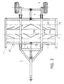
- the machine shown in the drawings is a trailed machine comprising a chassis 1 connected to a hitch 2; the articulation 3 between the coupling and the chassis making it possible to adjust the horizontality of the functional part of the machine by means of the jack 4.
- wheels 5 which can be lifted with a jack 6 are provided for the transport and, at work, for changes of direction.
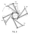
- a group of blades of the rotor 7 is shown in solid lines, as well as a blade of an adjacent group in broken lines.
- the four blades 10a, 10b, 10c, 10d respectively have their right ends and their left ends in two planes perpendicular to the axis of the rotor. They consist of longitudinal plates of rectangular shape whose cutting edge is sharp. Each blade is connected to the shaft 9 by two lateral arms 11 and 12 welded near each end and held in respective yokes 13 and 14 secured to the shaft 9.
- the blades all have the same arrangement relative to the axis of the rotor, namely an oblique arrangement according to which, at any point of their length, they are at a substantially constant distance from the axis.
- the ends of each blade are equidistant from the axis, but are angularly offset.
- the blades enter the earth at their most advanced end in the direction of rotation, then the penetration continues gradually along the leading edge to the other end.
- the efficiency of a blade thus arranged with respect to a blade parallel to the axis of the rotor is considerably increased.
- This penetrating power also depends on the angle at which the blade attacks the ground.
- this angle is close to 90 °, which gives, in practice, an inclination of the blades in their transverse direction for which the angle ⁇ , FIG. 3, has a value relatively close to 120 °.
- the rotor 7 divides on either side of its middle into a right part and a left part in which the obliquity of the blades is reversed, namely that if in the right part, the left ends of the blades are ahead in the direction of rotation on the right ends, in the left part, it is the right ends of the blades that are ahead of the left ends.
- the arms 11, 12 supporting the blades 10 are preferably provided in non-vertical longitudinal planes (considering the axis of the horizontal rotor), so that they obliquely meet obstacles such as stones present on the ground . Are thus avoided jolts of the machine and, as a result, irregularities in the work, because said obstacles, instead of being crossed by the arms 11 and 12, are driven to the side.
- the rear rotor 8 is similar but not identical to the rotor 7. Its blades 20 are arranged in the same way as on the rotor 7, but in opposition. This means that if the right end of the blades of the rotor 7 is in an advanced position relative to their left end, there is the opposite arrangement in the rotor 8 for the corresponding blades. Thus, when they cross, the blades of the two rotors are substantially parallel, so that the blades 20 of the rear rotor act effectively on the earth raised by the blades 10 of the front rotor.
- the rotor 7 has two right and left parts in which the obliquity of the blades is reversed, it is the same for the rotor 8, as shown in FIG. 2.
- the angle ⁇ of transverse inclination of the blades of the rotor 8 is also determined with a view to this efficiency of action on the ground raised by the blades of the front rotor.
- the cylindrical envelopes of the rotors 7 and 8 have equal radii and their rotation being ensured by rolling on the ground, they rotate at the same speed.
- a pinion or equivalent connection is provided between the front rotor 7 and the rear rotor 8, in order to ensure a higher speed of rotation of the latter.
- the radius of the rotor 8 is preferably smaller than that of the rotor 7, in order to reduce the depth of penetration into the ground and, consequently, the drive force of the front rotor 7.
- the increased rotational speed of the rear rotor 8 appreciably increases the spraying effect on the clods raised by the front rotor 7.
- the second rotor in addition to acting on the earth raised by the first, performs the same function as the latter relative to the third rotor , namely lifting the earth backwards so that it is taken up by the blades of the third rotor.
- the earth is somehow subjected to a double treatment.
- the machine as shown in the drawings is used to prepare the soil after plowing. We can add to it, at the rear, known tools such as leveling roller and / or seed drill.
- mounts such as 15 in FIG. 2 are provided to receive plowshares capable of ensuring in particular stubble cultivation.
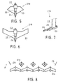
- Two embodiments of these plowshares marked respectively 21a and 21b, are shown in Figs. 5 to 8. They comprise, fixed to an upright 22, two symmetrical contiguous fins 23 running backwards and inclined longitudinally as shown in FIG. 7, at an angle of around 20 °.
- a center point 24 protrudes from the front of the fins 23. It is preferably fixed in a sheath 25, so as to be adjustable in translation.
- the coulters 21a and 21b differ essentially by the shape and the length of the fins 23. Substantially delta-shaped, the fins of the share 21a are shorter than those of the share 21b, which are practically parallelograms.
- the coulters 21a or 21b can be used interchangeably. However, particularly satisfactory results are obtained by arranging them in combination, according to the configuration in two rows of FIG. 8 where the arrow F indicates the front of the machine. Adjacent to the first rotor, not shown, one of the two rows consists of plowshares 21b whose neighboring ends are very close together. In front, plowshares 21a staggered with plowshares 21b form the other row. Deflectors 26 may also be provided at the ends of this row of plowshares 21a.
- the fins 21b are adjusted to penetrate the soil more deeply than the coulters 21a.
- the double row of coulters in addition to being able to ensure stubble cultivation, performs a preliminary work which favors the action of rotors.
- the three operations of stubble cultivation, soil preparation and seeding can be carried out in a single pass.
- the machine of the invention therefore allows significant savings, especially in working time. In addition, tests have shown that its effectiveness was satisfactory in wetlands.
- another important advantage of the machine of the invention lies in the fact that it is neither a heavy nor complex machine since, in its preferred embodiment, it comprises only two rotors for which, moreover , rotational drive means are not necessary.
Abstract
Description
La présente invention concerne une machine agricole du type des pulvériseurs servant à travailler le sol avant l'ensemencement, notamment pour éliminer les mottes. Elle concerne plus particulièrement une machine utilisable pour effectuer simultanément ce travail et le déchaumage.The present invention relates to an agricultural machine of the sprayer type used for working the soil before sowing, in particular for removing clods. It relates more particularly to a machine which can be used to simultaneously perform this work and stubble cultivation.
Il existe à ce jour des machines de ce type pour effectuer séparément l'une ou l'autre de ces tâches. Un déchaumeur connu et largement utilisé comprend une pluralité de rangées de disques transversales. Cette machine, uniquement conçue pour le déchaumage, n'effectue pas un émiettement suffisant des mottes, et un travail ultérieur de finition est toujours nécessaire.To date, there are machines of this type for performing one or the other of these tasks separately. A known and widely used cultivator comprises a plurality of rows of transverse discs. This machine, only designed for stubble cultivation, does not crumble the lumps enough, and further finishing work is always necessary.
Ce travail de finition peut être accompli au moyen d'une machine appelée cultivateur rotatif et comprenant un ou plusieurs rotors transversaux pourvus de doigts dirigés vers l'extérieur. Les rotors sont entraînés à partir de la prise de force d'un tracteur et la pulvérisation des mottes est réalisée entre les doigts de rotors adjacents. Outre le fait qu'elle réalise uniquement un travail de finition (après labour ou après déchaumage), cette machine a comme inconvénient important de n'être utilisable de façon efficace que si les conditions climatiques sont bonnes : si la terre est humide, il se produit du bourrage sur les doigts qui ne travaillent plus normalement.This finishing work can be accomplished by means of a machine called a rotary cultivator and comprising one or more transverse rotors provided with fingers pointing outwards. The rotors are driven from the PTO of a tractor and the clods are sprayed between the fingers of adjacent rotors. In addition to the fact that it only performs finishing work (after plowing or stubble cultivation), this machine has the significant disadvantage of being usable effectively only if the climatic conditions are good: if the soil is wet, it jams on fingers that are no longer working normally.
L'objet de la présente invention est de prévoir une machine utilisable pour effectuer simultanément le déchaumage et le travail de préparation du sol avant ensemencement qui, de plus, ne présente pas l'inconvénient mentionné ci-dessus d'être très sensible aux conditions climatiques.The object of the present invention is to provide a machine which can be used for simultaneous stubble cultivation and soil preparation work before sowing which, moreover, does not have the drawback mentioned above of being very sensitive to climatic conditions .
Pour répondre à cet objet, une machine selon l'invention est caractérisée en ce qu'elle comprend au moins deux rotors adjacents disposés transversalement l'un derrière l'autre, chaque rotor comprenant une pluralité de lames identiques de forme allongée réparties sur son pourtour et sur sa longueur, les lames ayant une fonction de pénétration dans le sol par un bord longitudinal, à une profondeur sensiblement constante d'une de leur extrémité à leur autre extrémité, et de soulèvement vers l'arrière de la terre, les lames du ou des rotors autres que le premier ayant pour fonction supplémentaire de casser les mottes soulevées vers l'arrière par les lames du rotor qui précède.To meet this object, a machine according to the invention is characterized in that it comprises at least two adjacent rotors arranged transversely one behind the other, each rotor comprising a plurality of identical blades of elongated shape distributed around its periphery and along its length, the blades having a function of penetrating into the ground by a longitudinal edge, to a substantially constant depth from one of their ends to their other ends, and of lifting up the rear of the earth, the blades of the or rotors other than the first having the additional function of breaking the clods raised rearward by the blades of the preceding rotor.
Dans une forme de réalisation préférée de l'invention, lesdites lames sont disposées obliquement par rapport à l'axe du rotor, de sorte que leur bord d'attaque entre progressivement dans la terre à mesure que le rotor tourne.In a preferred embodiment of the invention, said blades are arranged obliquely to the axis of the rotor, so that their leading edge gradually enters the earth as the rotor turns.
Les rotors peuvent être entraînés à partir de la prise de force d'un tracteur. Néanmoins, dans une forme de réalisation satisfaisante, le simple roulement des rotors sur le sol est suffisant. Dans tous les cas, un dispositif de transmission entre les rotors est éventuellement prévu pour assurer une vitesse de rotation plus élevée du ou des rotors autres que le premier.The rotors can be driven from the PTO of a tractor. However, in a satisfactory embodiment, the simple rolling of the rotors on the ground is sufficient. In all cases, a transmission device between the rotors is possibly provided to ensure a higher speed of rotation of the rotor or rotors other than the first.
L'invention sera mieux comprise à l'aide des explications qui vont suivre, et des dessins joints, dans lesquels :
- la Fig. 1 est une vue schématique de côté d'une machine selon l'invention,
- la Fig. 2 est une vue schématique de dessus de la machine de la Fig. 1,
- la Fig. 3 est vue de côté représentant schématiquement l'arrangement des lames sur le rotor avant de la machine des Figs. 1 et 2,
- la Fig. 4 est une vue de côté schématique illustrant l'arrangement des rotors,
- les Figs. 5 et 6 sont des vues schématiques, de dessus, représentant des socs pouvant être placés devant le premier rotor,
- la Fig. 7 est une vue de côté du soc de la Fig. 6, et
- la Fig. 8 est une vue schématique, en plan, d'une disposition de socs préférentielle dans une machine selon l'invention.
- Fig. 1 is a schematic side view of a machine according to the invention,
- Fig. 2 is a schematic top view of the machine of FIG. 1,
- Fig. 3 is a side view schematically showing the arrangement of the blades on the front rotor of the machine of FIGS. 1 and 2,
- Fig. 4 is a schematic side view illustrating the arrangement of the rotors,
- Figs. 5 and 6 are schematic views from above, representing plowshares which can be placed in front of the first rotor,
- Fig. 7 is a side view of the share of FIG. 6, and
- Fig. 8 is a schematic plan view of a preferred coulter arrangement in a machine according to the invention.
La machine représentée sur les dessins est une machine traînée comprenant un châssis 1 relié à un attelage 2; l'articulation 3 entre l'attelage et le châssis permettant de régler l'horizontalité de la partie fonctionnelle de la machine au moyen du vérin 4. A l'arrière du bâti 1, des roues 5 relevables avec un vérin 6 sont prévues pour le transport et, au travail, pour les changements de direction.The machine shown in the drawings is a trailed machine comprising a
Le châssis 1 porte un rotor avant 7 et un rotor arrière 8. Les rotors 7 et 8 sont montés autour d'axes horizontaux perpendiculaires à la direction d'avancement. Dans la forme de réalisation montrée, ils sont au même niveau et ont le même diamètre extérieur, de manière à opérer sensiblement à la même profondeur, la profondeur de travail étant obtenue, soit par le poids de la machine que l'on augmente, si nécessaire, avec des masses d'alourdissement, ou bien par des roues de terrage placées à l'avant du premier rotor 7. De préférence, des moyens de protection tels que grillage sont prévus au-dessus des rotors 7 et 8, à des fins de sécurité.The
Comme le montrent mieux les Figs. 2 et 3, le rotor avant 7 comporte un arbre 9 sur lequel sont montées des lames 10, réparties sur la longueur en i groupes identiques, chaque groupe comprenant j lames régulièrement placées sur le pourtour, avec ici i = 6 et j = 4. A la Fig. 3, un groupe de lames du rotor 7 est représenté en traits pleins, ainsi qu'une lame d'un groupe adjacent en traits interrompus.As best shown in Figs. 2 and 3, the front rotor 7 comprises a shaft 9 on which
Dans ledit groupe, les quatres lames 10a, 10b, 10c, 10d ont respectivement leurs extrémités de droite et leurs extrémités de gauche dans deux plans perpendiculaires à l'axe du rotor. Elle consistent en des plaquettes longitudinales de forme rectangulaire dont le bord d'attaque est tranchant. Chaque lame est reliée à l'arbre 9 par deux bras latéraux 11 et 12 soudés près de chaque extrémité et maintenus dans des chapes respectives 13 et 14 solidaires de l'arbre 9.In said group, the four
Comme le montrent les dessins, les lames ont toutes la même disposition par rapport à l'axe du rotor, à savoir une disposition oblique selon laquelle, en tout point de leur longueur, elles sont à une distance sensiblement constante de l'axe. En d'autre termes, les extrémités de chaque lame se trouvent à égale distance de l'axe, mais sont décalées angulairement. Ainsi, en travail, les lames entrent dans la terre par leur extrémité la plus avancée dans le sens de rotation, puis la pénétration se poursuit progressivement le long du bord d'attaque jusqu'à l'autre extrémité. L'efficacité d'une lame ainsi disposée par rapport à une lame parallèle à l'axe du rotor est considérablement augmentée.As shown in the drawings, the blades all have the same arrangement relative to the axis of the rotor, namely an oblique arrangement according to which, at any point of their length, they are at a substantially constant distance from the axis. In other words, the ends of each blade are equidistant from the axis, but are angularly offset. Thus, in work, the blades enter the earth at their most advanced end in the direction of rotation, then the penetration continues gradually along the leading edge to the other end. The efficiency of a blade thus arranged with respect to a blade parallel to the axis of the rotor is considerably increased.
Ce pouvoir de pénétration dépend également de l'angle selon lequel la lame attaque le sol. De préférence, cet angle est voisin de 90°, ce qui donne, en pratique, une inclinaison des lames dans leur direction transversale pour laquelle l'angle α, Fig. 3, a une valeur relativement voisine de 120°.This penetrating power also depends on the angle at which the blade attacks the ground. Preferably, this angle is close to 90 °, which gives, in practice, an inclination of the blades in their transverse direction for which the angle α, FIG. 3, has a value relatively close to 120 °.
On notera par ailleurs que, de préférence, le rotor 7 se divise de part et d'autre de son milieu en une partie de droite et une partie de gauche dans lesquelles l'obliquité des lames est inversée, à savoir que si dans la partie de droite, les extrémités de gauche des lames sont en avance dans le sens de rotation sur les extrémités de droite, dans la partie de gauche, ce sont les extrémités de droite des lames qui sont en avance sur les extrémités de gauche. Avec un tel arrangement, les efforts sur le rotor au travail sont répartis de façon symétrique par rapport à l'axe longitudinal de la machine qui, par conséquent, reste bien en ligne derrière le tracteur.It will also be noted that, preferably, the rotor 7 divides on either side of its middle into a right part and a left part in which the obliquity of the blades is reversed, namely that if in the right part, the left ends of the blades are ahead in the direction of rotation on the right ends, in the left part, it is the right ends of the blades that are ahead of the left ends. With such an arrangement, the forces on the rotor at work are distributed symmetrically with respect to the longitudinal axis of the machine which, therefore, remains well in line behind the tractor.
Les bras 11, 12 supportant les lames 10 sont, de préférence, prévus dans des plans longitudinaux non verticaux (en considérant l'axe du rotor horizontal), de manière à ce qu'ils rencontrent obliquement des obstacles tels que cailloux présents sur le sol. Sont ainsi évités des soubresauts de la machine et, par suite, des irrégularités du travail, du fait que lesdits obstacles, au lieu d'être franchis par les bras 11 et 12, sont chassés sur le côté.The
On voit, d'autre part, aux Figs. 2 et 3 que dans les groupes de lames successifs du rotor 7, les lames correspondantes telles que 10a, 10′a, 10˝a sont légèrement décalées angulairement d'un groupe au groupe adjacent. On assure ainsi un roulement sans à-coup du rotor, du fait qu'en un lieu quelconque sur la longueur du rotor, quand une lame sort de terre, une lame voisine y est suffisamment engagée.We see, on the other hand, in Figs. 2 and 3 that in the groups of successive blades of the rotor 7, the corresponding blades such as 10a, 10′a, 10˝a are slightly angularly offset from one group to the adjacent group. This ensures smooth rotation of the rotor, because in any place along the length of the rotor, when a blade comes out of the ground, a neighboring blade is sufficiently engaged.
Le rotor arrière 8 est semblable mais non identique au rotor 7. Ses lames 20 sont arrangées de la même façon que sur le rotor 7, mais en opposition. Cela signifie que si l'extrémité droite de lames du rotor 7 est en position avancée par rapport à leur extrémité gauche, on a la disposition contraire dans le rotor 8 pour les lames correspondantes. Ainsi, lorsqu'elles se croisent, les lames des deux rotors sont sensiblement parallèles, de sorte que les lames 20 du rotor arrière agissent efficacement sur la terre soulevée par les lames 10 du rotor avant. Par voie de conséquence, si comme on l'a précisé précédemment à propos d'une forme de réalisation préférée, le rotor 7 comporte deux parties droite et gauche dans lesquelles l'obliquité des lames est inversée, il en est de même pour le rotor 8, comme le montre la Fig. 2. D'autre part, l'angle β d'inclinaison transversale des lames du rotor 8 est déterminé également en vue de cette efficacité d'action sur la terre soulevée par les lames du rotor avant. De préférence, afin d'avoir un bon effet de tranchant sur les mottes, on cherche à ce que les lames du rotor arrière 8 se présentent sensiblement perpendiculairement à celles-ci, et l'angle β correspondant est voisin de 90°.The
Dans l'exemple illustré, les enveloppes cylindriques des rotors 7 et 8 ont des rayons égaux et leur rotation étant assurée par roulement sur le sol, ils tournent à la même vitesse. Dans une variante, une liaison par pignon ou équivalent est prévue entre le rotor avant 7 et le rotor arrière 8, afin d'assurer une vitesse de rotation plus élevée de ce dernier. Dans ce cas, le rayon du rotor 8 est, de préférence, plus petit que celui du rotor 7, afin d'en diminuer la profondeur de pénétration dans le sol et, par conséquent, l'effort d'entraînement du rotor avant 7. La vitesse de rotation accrue du rotor arrière 8 augmente sensiblement l'effet de pulvérisation sur les mottes soulevées par le rotor avant 7.In the example illustrated, the cylindrical envelopes of the
Au cas où une machine selon l'invention comporte plus de deux rotors successifs, par exemple trois, le deuxième rotor, en plus d'agir sur la terre soulevée par le premier, accomplit la même fonction que celui-ci par rapport au troisième rotor, à savoir soulever la terre vers l'arrière de manière qu'elle soit reprise par les lames du troisième rotor. Dans une telle forme de réalisation, la terre est en quelque sorte soumise à un double traitement.If a machine according to the invention has more than two successive rotors, for example three, the second rotor, in addition to acting on the earth raised by the first, performs the same function as the latter relative to the third rotor , namely lifting the earth backwards so that it is taken up by the blades of the third rotor. In such an embodiment, the earth is somehow subjected to a double treatment.
La machine telle que représentée dans les dessins est utilisée pour préparer le sol après un labour. On peut lui adjoindre, à l'arrière, des outils connus tels que rouleau niveleur et/ou semoir.The machine as shown in the drawings is used to prepare the soil after plowing. We can add to it, at the rear, known tools such as leveling roller and / or seed drill.
A l'avant, des montures telles que 15 à la Fig. 2 sont prévues pour recevoir des socs aptes à assurer notamment le déchaumage. Deux formes de réalisation de ces socs, repérées respectivement 21a et 21b, sont représentées aux Figs. 5 à 8. Elles comportent, fixés à un montant 22, deux ailerons jointifs symétriques 23 fuyant vers l'arrière et inclinés longitudinalement comme montré à la Fig. 7, selon un angle de l'ordre de 20°. Une pointe médiane 24 dépasse à l'avant des ailerons 23. Elle est de préférence fixée dans un fourreau 25, de manière à être réglable en translation.At the front, mounts such as 15 in FIG. 2 are provided to receive plowshares capable of ensuring in particular stubble cultivation. Two embodiments of these plowshares, marked respectively 21a and 21b, are shown in Figs. 5 to 8. They comprise, fixed to an
Les socs 21a et 21b différent essentiellement par la forme et la longueur des ailerons 23. Sensiblement en forme de delta, les ailerons du soc 21a sont moins longs que ceux du soc 21b, lesquels sont pratiquement des parallélogrammes.The
On peut utiliser indifféremment les socs 21a ou 21b. Toutefois, on obtient des résultats particulièrement satisfaisants en les arrangeant en combinaison, selon la configuration en deux rangées de la Fig. 8 où la flèche F indique l'avant de la machine. Adjacente au premier rotor, non représenté, l'une des deux rangées est constituée de socs 21b dont les extrémités voisines sont très rapprochées. Devant, des socs 21a disposés en quinconce avec les socs 21b forment l'autre rangée. Des déflecteurs 26 peuvent en outre être prévus aux extrémités de cette rangée de socs 21a.The
De préférence, les ailerons 21b sont réglés pour pénétrer plus profondément la terre que les socs 21a. La double rangée de socs, en plus d'être apte à assurer le déchaumage, réalise un travail préalable qui favorise l'action des rotors. Avec une machine ainsi équipée, et à l'arrière de laquelle est adjoint un semoir, les trois opérations de déchaumage, préparation du sol et ensemencement peuvent être effectuées en un seul passage.Preferably, the
La machine de l'invention permet donc des économies importantes, notamment en temps de travail. Par ailleurs, des essais ont permis de constater que son efficacité était satisfaisante en terre humide. De plus, un autre avantage important de la machine de l'invention réside dans le fait qu'elle n'est un engin ni lourd, ni complexe puisque, dans sa forme de réalisation préférée, elle comprend seulement deux rotors pour lesquels, de plus, des moyens d'entraînement en rotation ne sont pas nécessaires.The machine of the invention therefore allows significant savings, especially in working time. In addition, tests have shown that its effectiveness was satisfactory in wetlands. In addition, another important advantage of the machine of the invention lies in the fact that it is neither a heavy nor complex machine since, in its preferred embodiment, it comprises only two rotors for which, moreover , rotational drive means are not necessary.
Claims (15)
Applications Claiming Priority (2)
| Application Number | Priority Date | Filing Date | Title |
|---|---|---|---|
| FR8911684 | 1989-09-04 | ||
| FR8911684A FR2651407B1 (en) | 1989-09-04 | 1989-09-04 | MACHINE FOR PREPARING THE SOIL BEFORE SOWING. |
Publications (1)
| Publication Number | Publication Date |
|---|---|
| EP0417023A1 true EP0417023A1 (en) | 1991-03-13 |
Family
ID=9385201
Family Applications (1)
| Application Number | Title | Priority Date | Filing Date |
|---|---|---|---|
| EP90460030A Withdrawn EP0417023A1 (en) | 1989-09-04 | 1990-09-03 | Machine for preparing the soil for sowing |
Country Status (2)
| Country | Link |
|---|---|
| EP (1) | EP0417023A1 (en) |
| FR (1) | FR2651407B1 (en) |
Cited By (2)
| Publication number | Priority date | Publication date | Assignee | Title |
|---|---|---|---|---|
| EP1188359A3 (en) * | 2000-09-13 | 2004-06-16 | Clark Equipment Company | Soil conditioner implement |
| CN104956791A (en) * | 2015-06-17 | 2015-10-07 | 徐先平 | Double-shaft rotary cultivator |
Citations (6)
| Publication number | Priority date | Publication date | Assignee | Title |
|---|---|---|---|---|
| US1830565A (en) * | 1928-01-30 | 1931-11-03 | Schaeffers Joseph | Rotary plow |
| US2776533A (en) * | 1952-10-11 | 1957-01-08 | Paul E Yacoby | Power driven vehicle with interchangeable rotary tool |
| GB1156396A (en) * | 1966-07-01 | 1969-06-25 | Fmc Corp | Apparatus for preparing Soil |
| FR2354690A1 (en) * | 1976-06-17 | 1978-01-13 | Texas Industries Inc | MACHINE USED TO WORK THE SOIL |
| US4077477A (en) * | 1972-06-23 | 1978-03-07 | C. Van Der Lely N.V. | Soil cultivating implements |
| EP0035843A1 (en) * | 1980-03-11 | 1981-09-16 | Bomford And Evershed Limited | Soil surface cultivating machine |
-
1989
- 1989-09-04 FR FR8911684A patent/FR2651407B1/en not_active Expired - Fee Related
-
1990
- 1990-09-03 EP EP90460030A patent/EP0417023A1/en not_active Withdrawn
Patent Citations (6)
| Publication number | Priority date | Publication date | Assignee | Title |
|---|---|---|---|---|
| US1830565A (en) * | 1928-01-30 | 1931-11-03 | Schaeffers Joseph | Rotary plow |
| US2776533A (en) * | 1952-10-11 | 1957-01-08 | Paul E Yacoby | Power driven vehicle with interchangeable rotary tool |
| GB1156396A (en) * | 1966-07-01 | 1969-06-25 | Fmc Corp | Apparatus for preparing Soil |
| US4077477A (en) * | 1972-06-23 | 1978-03-07 | C. Van Der Lely N.V. | Soil cultivating implements |
| FR2354690A1 (en) * | 1976-06-17 | 1978-01-13 | Texas Industries Inc | MACHINE USED TO WORK THE SOIL |
| EP0035843A1 (en) * | 1980-03-11 | 1981-09-16 | Bomford And Evershed Limited | Soil surface cultivating machine |
Cited By (2)
| Publication number | Priority date | Publication date | Assignee | Title |
|---|---|---|---|---|
| EP1188359A3 (en) * | 2000-09-13 | 2004-06-16 | Clark Equipment Company | Soil conditioner implement |
| CN104956791A (en) * | 2015-06-17 | 2015-10-07 | 徐先平 | Double-shaft rotary cultivator |
Also Published As
| Publication number | Publication date |
|---|---|
| FR2651407A1 (en) | 1991-03-08 |
| FR2651407B1 (en) | 1992-02-14 |
Similar Documents
| Publication | Publication Date | Title |
|---|---|---|
| EP1976367B1 (en) | Machine for working the soil, such as a disc tiller | |
| FR2583258A1 (en) | ROTATING MOWER | |
| EP0641157B1 (en) | Machine for the destruction of banana plantation debris | |
| EP2923539B1 (en) | Seed drill with built-in roller for destroying plant cover | |
| EP0287487A2 (en) | Soil cultivating machine having a rotary shaft transverse to the direction of travel | |
| EP0217720B1 (en) | Agricultural soil-tilling machine with a rotor driven around an oblique axis | |
| EP0200578A1 (en) | Combined machine to break up and crumble the soil | |
| EP0417023A1 (en) | Machine for preparing the soil for sowing | |
| WO2002094001A1 (en) | Multipurpose tilling device | |
| FR2543784A1 (en) | Reversible soil-inversion cultivator | |
| EP0342065B1 (en) | Implement for treating ploughed land | |
| EP2268122B1 (en) | Farm machine for destroying plant cover on soil by mechanical removal | |
| FR2485868A1 (en) | SOIL WORKING MACHINE SUITABLE IN PARTICULAR FOR THE PREPARATION OF SEED BEDS | |
| EP0470026B1 (en) | Multi-purpose rotary plough | |
| FR2687535A1 (en) | Combined agricultural implement for grubbing (clearing), breaking-up (loosening) the soil and direct sowing | |
| FR2589667A1 (en) | Ridging plough with inclined rotors | |
| WO2022184862A1 (en) | Device, vehicle and method for working soil in agriculture, arboriculture and truffle growing | |
| EP0346255B1 (en) | Soilworking machine provided with shares and a rotor | |
| FR2619667A1 (en) | Improvement to agricultural tools for reworking ploughing | |
| FR2597698A1 (en) | COMBINATION INSTRUMENT FOR GRINDING, DEFRICHING AND WORKING OF THE SOIL. | |
| EP0408417B1 (en) | Classifying and enclosing device for a stone swath former drawn by a tractor, of the type having two axes forming a "V" with respect to the direction of motion of the tractor, and having resilient and vibratable teeth | |
| FR2862477A1 (en) | Stubble-ploughing device for e.g. preparing ground to sow, includes work module, supplement module and finishing module, where work module comprises of two rows of oblique discs that rotate freely | |
| FR2990100A1 (en) | Agricultural machine for tillage of soil for maintenance of e.g. orchards, has drive mechanism driving rotor in negative direction with respect to working direction, so that spades move forward upon contact with soil | |
| FR2755343A1 (en) | Agricultural machine for working the soil | |
| FR2824698A1 (en) | Multi-function soil cultivating implement has single row of cutting tools followed by two staggered rows of coulters, seed drills and rollers |
Legal Events
| Date | Code | Title | Description |
|---|---|---|---|
| PUAI | Public reference made under article 153(3) epc to a published international application that has entered the european phase |
Free format text: ORIGINAL CODE: 0009012 |
|
| AK | Designated contracting states |
Kind code of ref document: A1 Designated state(s): AT BE DE DK ES FR GB IT NL SE |
|
| STAA | Information on the status of an ep patent application or granted ep patent |
Free format text: STATUS: THE APPLICATION IS DEEMED TO BE WITHDRAWN |
|
| 18D | Application deemed to be withdrawn |
Effective date: 19910914 |