EP0416452A2 - Elektrofilterkabel - Google Patents
Elektrofilterkabel Download PDFInfo
- Publication number
- EP0416452A2 EP0416452A2 EP90116546A EP90116546A EP0416452A2 EP 0416452 A2 EP0416452 A2 EP 0416452A2 EP 90116546 A EP90116546 A EP 90116546A EP 90116546 A EP90116546 A EP 90116546A EP 0416452 A2 EP0416452 A2 EP 0416452A2
- Authority
- EP
- European Patent Office
- Prior art keywords
- cable
- filter cable
- electrical conductor
- cable according
- electrostatic
- Prior art date
- Legal status (The legal status is an assumption and is not a legal conclusion. Google has not performed a legal analysis and makes no representation as to the accuracy of the status listed.)
- Granted
Links
Images

Classifications
-
- H—ELECTRICITY
- H01—ELECTRIC ELEMENTS
- H01B—CABLES; CONDUCTORS; INSULATORS; SELECTION OF MATERIALS FOR THEIR CONDUCTIVE, INSULATING OR DIELECTRIC PROPERTIES
- H01B7/00—Insulated conductors or cables characterised by their form
- H01B7/0054—Cables with incorporated electric resistances
Definitions
- the invention relates to an electrostatic precipitator cable for an electrostatic precipitator system with an inner electrical conductor, an insulation made of cross-linked polyethylene, an outer conductive layer, a copper screen and a PVC outer jacket.
- Such an electrostatic filter cable is e.g. known from the cable + wire publication K + D 1060D (2.78) MGD, page 1.
- This electrostatic precipitator cable has a round, multi-wire aluminum conductor as the inner electrical conductor and is used in an electrostatic precipitator system to connect a high-voltage rectifier system to a spray wire arranged in a filter housing.
- the filter housing is at earth potential.
- the invention has for its object to provide an electrostatic filter cable, with the help of which the structure of an electrostatic filter system can be simplified.
- the inner electrical conductor consists of a conductive plastic with a specific resistance in the range 2 to 200 ⁇ mm2 / m.
- the advantages that can be achieved with the invention consist in particular in that, by using the proposed electrostatic filter cable, damping resistances no longer have to be provided between the spray wire, electrostatic filter cable and rectifier system.
- the proposed electrostatic precipitator cable also takes on the function of damping the overvoltages that occur in the electrostatic filter system during the intended flashovers.
- the weight of the electrostatic filter cable is advantageously reduced. Handling is also simplified. If the tensile strength of the proposed electrostatic filter cable is not sufficient, additional tensile materials can be introduced into the inner electrical conductor.
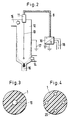
- the electrostatic filter cable has a conductor 1 made of an electrically conductive plastic.
- conductive polymers e.g. a PE copolymer
- polypyrroles can be used as conductive plastics for the conductor 1.
- the specific electrical resistance ranges from 2 to 200 ⁇ mm2 / m and is preferably 10 ⁇ mm2 / m. However, the exact value to be selected depends to a large extent on the type, embodiment, operating mode and performance of the electrostatic precipitator used.
- the conductor 1 made of conductive plastic can be encased by an inner conductive layer 2.
- This inner conductive layer 2 can be dispensed with if, for example, a conductive polymer with a smooth surface is used as conductor 1, since it is then not necessary to smooth the conductor 1 to ensure that the field strength occurring on the surface is reliably controlled.
- the inner conductive layer 2 or directly the conductor 1 are surrounded by an insulation 3 made of cross-linked polyethylene (VPE).
- the insulation 3 is encased by an outer conductive layer 4 made of an electrically conductive application or an extruded one conductive material. This is followed by a further outer conductive layer 5 made of a conductive tape.
- the outer guiding layers 4, 5 serving to limit the field are covered by a copper screen consisting of copper wires with a counter helix.
- a separating layer 7 and a PVC outer jacket 8 follow.
- Fig. 2 shows the use of an electrostatic filter cable in an electrostatic filter system.
- the electrostatic filter cable 9 can be seen, which is connected on the one hand to a rectifier system 10 and, on the other hand, reaches into the interior of a cylindrical dust filter housing 12 of the electrostatic filter system via an insulator 11 and applies a high direct voltage to a spray wire 13 there.
- the metallic, electrically conductive dust removal filter housing 12 has a raw gas inlet opening 14 arranged laterally in its lower part, a clean gas outlet opening 15 located laterally in its upper part and a dust outlet opening 16 arranged centrally in its lower part.
- the raw gas inlet, the clean gas outlet and the dust outlet are each indicated by arrows.
- Numeral 17 designates the ground cable of the dedusting filter housing 12 on the one hand and the rectifier system 10 on the other.
- the rectifier system 10 is supplied by a three-phase supply 18.
- FIG. 3 and 4 different variants are shown in the design of the inner electrical conductor of the electrostatic filter cable.
- the tensile strength of the conductor 1 and thus of the electrostatic filter cable can be increased considerably by the variants shown.
- a central strand 19 is provided in the inner electrical conductor 1, while according to FIG. 4 several — in the example four — individual strands 20 are arranged symmetrically distributed in the conductor 1.
- the central strand 19 or the individual strands 20 consist of a tensile, electrically non-conductive material, preferably of a very tensile, electrically non-conductive plastic, such as e.g. Polyamide, polypropylene or similar (against glass fiber reinforced).
- a very tensile, electrically non-conductive plastic such as e.g. Polyamide, polypropylene or similar (against glass fiber reinforced).
- it is also possible to dispense with the additional incorporation of these tensile materials if the electrostatic filter cable equipped with a conduct
Abstract
Description
- Die Erfindung bezieht sich auf ein Elektrofilterkabel für eine Elektrofilteranlage mit einem inneren elektrischen Leiter, einer Isolierung aus vernetztem Polyethylen, einer äußeren Leitschicht, einem Kupferschirm und einem PVC-Außenmantel.
- Ein solches Elektrofilterkabel ist z.B. aus der Kabel + Draht-Druckschrift K+D 1060D (2.78) MGD, Seite 1 bekannt. Dieses Elektrofilterkabel besitzt einen runden, mehrdrähtigen Aluminium-Leiter als inneren elektrischen Leiter und dient bei einer Elektrofilteranlage zur Verbindung einer hochspannungserzeugenden Gleichrichteranlage mit einem in einem Filtergehäuse angeordneten Sprühdraht. Das Filtergehäuse liegt dabei auf Erdpotential.
- In Elektrofilteranlagen treten bestimmungsgemäß elektrische Überschläge zwischen Hochspannungs- und Erdpotential auf. Um die dabei entstehenden Stoßspannungen zu dämpfen, werden üblicherweise zwischen dem Sprühdraht, dem Elektrofilterkabel und der hochspannungserzeugenden Gleichrichteranlage Dämpfungswiderstände eingefügt.
- Der Erfindung liegt die Aufgabe zugrunde, ein Elektrofilterkabel anzugeben, mit dessen Hilfe der Aufbau einer Elektrofilteranlage vereinfacht werden kann.
- Diese Aufgabe wird in Verbindung mit den Merkmalen des Oberbegriffes erfindungsgemäß dadurch gelöst, daß der innere elektrische Leiter aus einem leitfähigen Kunststoff mit einem spezifischen Widerstand im Bereich 2 bis 200 Ω mm²/m besteht.
- Die mit der Erfindung erzielbaren Vorteile bestehen insbesondere darin, daß durch den Einsatz des vorgeschlagenen Elektrofilterkabels keine Dämpfungswiderstände mehr zwischen Sprühdraht, Elektrofilterkabel und Gleichrichteranlage vorgesehen werden müssen. Das vorgeschlagene Elektrofilterkabel übernimmt neben der Funktion der Hochspannungszuführung zum Sprühdraht auch die Funktion der Dämpfung der bei den bestimmungsgemäßen Überschlägen in der Elektrofilteranlage auftretenden Überspannungen. Infolge des Einsatzes von Kunststoff als innerem elektrischen Leiter wird das Gewicht des Elektrofilterkabels vorteilhaft verringert. Desweiteren wird die Handhabung vereinfacht. Falls die Zugfestigkeit des vorgeschlagenen Elektrofilterkabels nicht ausreicht, können zusätzlich zugfeste Materialien in den inneren elektrischen Leiter eingebracht werden.
- Die Erfindung wird nachstehend anhand der in der Zeichnung dargestellten Ausführungsbeispiele erläutert.
- Es zeigen:
- Fig. 1 den Aufbau eines Elektrofilterkabels,
- Fig. 2 den Einsatz eines Elektrofilterkabels in einer Elektrofilteranlage,
- Fig. 3 und 4 verschiedene Varianten bei der Ausführung des inneren elektrischen Leiters des Elektrofilterkabels.
- In Fig. 1 ist der Aufbau eines Elektrofilterkabels dargestellt. Das Elektrofilterkabel weist einen Leiter 1 aus einem elektrisch leitfähigen Kunststoff auf. Je nach Widerstandsanforderung können in der Kabeltechnik angewandte leitfähige Polymere (z.B. ein PE-Copolymer), wie sie z.B. für innere und äußere Leitschichten von Kabeln bekannt sind, verwendet werden. Weiterhin können Polypyrrole als leitfähige Kunststoffe für den Leiter 1 eingesetzt werden. Mit Hilfe dieser Materialien ist der Leitwert des Leiters 1 je nach Anforderung in weiten Grenzen variabel vorgebbar. Der spezifische elektrische Widerstand bewegt sich im Bereich von 2 bis 200 Ω mm²/m und liegt vorzugsweise bei 10 Ω mm²/m. Der genaue zu wählende Wert ist jedoch in weitem Ausmaß abhängig von der Art, Ausführungsform, Betriebsart und Leistungsfähigkeit der verwendeten Elektrofilteranlage.
- Der Leiter 1 aus leitfähigem Kunststoff kann von einer inneren Leitschicht 2 umhüllt sein. Diese innere Leitschicht 2 ist entbehrlich, wenn z.B. ein Leitpolymer mit glatter Oberfläche als Leiter 1 eingesetzt wird, da dann eine Glättung des Leiters 1 zur Gewährleistung einer sicheren Beherrschung der an der Oberfläche auftretenden Feldstärke nicht notwendig ist. Die innere Leitschicht 2 bzw. direkt der Leiter 1 sind umgeben von einer Isolierung 3 aus vernetztem Polyethylen (VPE). Die Isolierung 3 ist umhüllt von einer äußeren Leitschicht 4 aus einem elektrisch leitenden Auftrag oder einem extrudierten leitfähigen Material. Es schließt sich eine weitere äußere Leitschicht 5 aus einem leitfähigen Band an.
- Die zur Feldbegrenzung dienenden äußeren Leitschichten 4, 5 sind von einem Kupferschirm, bestehend aus Kupferdrähten mit einer Gegenwendel, umhüllt. Es schließen sich eine Trennschicht 7 und ein PVC-Außenmantel 8 an.
- Fig. 2 zeigt den Einsatz eines Elektrofilterkabels in einer Elektrofilteranlage. Es ist das Elektrofilterkabel 9 zu erkennen, das einerseits an eine Gleichrichteranlage 10 angeschlossen ist und andererseits über einen Isolator 11 in den Innenraum eines zylindrischen Entstaubungsfiltergehäuses 12 der Elektrofilteranlage greift und dort einen Sprühdraht 13 mit hoher Gleichspannung beaufschlagt. Das metallische, elektrisch leitfähige Entstaubungsfiltergehäuse 12 weist eine in seinem unteren Teil seitlich angeordnete Rohgaseintrittsöffnung 14, eine sich in seinem oberen Teil seitlich befindende Reingasaustrittsöffnung 15 und eine in seinem unteren Teil zentral angeordnete Staubaustrittsöffnung 16 auf. Der Rohgaseintritt, der Reingasaustritt und der Staubaustritt sind jeweils durch Pfeile angedeutet. Der aus dem Rohgas stammende und von der angelegten hohen Gleichspannung zur Wandung des Entstaubungsfiltergehäuses 12 getriebene Staub ist gepunktet dargestellt. Mit Ziffer 17 sind die Massekabel des Entstaubungsfiltergehäuses 12 einerseits und der Gleichrichteranlage 10 andererseits bezeichnet. Die Gleichrichteranlage 10 wird von einer Drehstromeinspeisung 18 versorgt.
- In der Elektrofilteranlage treten bestimmungsgemäß elektrische Überschläge zwischen dem auf Hochspannungspotential liegenden Sprühdraht 13 und dem auf Massepotential liegenden Entstaubungsfiltergehäuse 12 auf. Die Gleichspannung steigt dabei entsprechend einer Aufladekurve eines Kondensators bis zum Überschlag im Entstaubungsfiltergehäuse an und bricht beim Überschlag schlagartig zusammen, worauf der Ladevorgang von neuem beginnt. Der ohmsche Widerstandswert des Elektrofilterkabels 9 übernimmt dabei die Funktion eines Dämpfungswiderstandes zur Dämpfung der zwischen Entstaubungsfiltergehäuse bzw. Sprühdraht 13, Elektrofilterkabel 9 und Gleichrichteranlage 10 auftretenden Stoßspannungen.
- In den Fig. 3 und 4 sind verschiedene Varianten bei der Ausführung des inneren elektrischen Leiters des Elektrofilterkabels dargestellt. Durch die gezeigten Varianten kann die Zugfestigkeit des Leiters 1 und damit des Elektrofilterkabels beträchtlich erhöht werden. Gemäß Fig. 3 ist ein Zentralstrang 19 im inneren elektrischen Leiter 1 vorgesehen, während gemäß Fig. 4 mehrere - im Beispiel vier - Einzelstränge 20 symmetrisch verteilt im Leiter 1 angeordnet sind. Der Zentralstrang 19 bzw. die Einzelstränge 20 bestehen dabei aus einem zugfesten, elektrisch nichtleitenden Material, vorzugsweise aus einem sehr zugfesten, elektrisch nichtleitenden Kunststoff, wie z.B. Polyamid, Polypropylen o.ä. (geg. glasfaserverstärkt). Je nach Anwendungsfall kann auch auf die zusätzliche Einlagerung dieser zugfesten Materialien verzichtet werden, wenn das mit einem Leiter 1 aus leitfähigem Kunststoff ausgerüstete Elektrofilterkabel eine den gesetzten Anforderungen entsprechende Zugfestigkeit aufweist.
Claims (8)
Applications Claiming Priority (2)
| Application Number | Priority Date | Filing Date | Title |
|---|---|---|---|
| DE3929450A DE3929450A1 (de) | 1989-09-05 | 1989-09-05 | Elektrofilterkabel |
| DE3929450 | 1989-09-05 |
Publications (3)
| Publication Number | Publication Date |
|---|---|
| EP0416452A2 true EP0416452A2 (de) | 1991-03-13 |
| EP0416452A3 EP0416452A3 (en) | 1992-04-29 |
| EP0416452B1 EP0416452B1 (de) | 1996-02-14 |
Family
ID=6388662
Family Applications (1)
| Application Number | Title | Priority Date | Filing Date |
|---|---|---|---|
| EP90116546A Expired - Lifetime EP0416452B1 (de) | 1989-09-05 | 1990-08-29 | Elektrofilterkabel |
Country Status (3)
| Country | Link |
|---|---|
| US (1) | US5068497A (de) |
| EP (1) | EP0416452B1 (de) |
| DE (2) | DE3929450A1 (de) |
Cited By (3)
| Publication number | Priority date | Publication date | Assignee | Title |
|---|---|---|---|---|
| FR2723245A1 (fr) * | 1994-08-01 | 1996-02-02 | Cortaillod Cables Sa | Cable de transport d'energie electrique ou de telecommunication et procede de fabrication d'un tel cable |
| EP0782151A1 (de) * | 1995-12-28 | 1997-07-02 | Alcatel | Herstellungsverfahren von einem verbesserten elektrisch leitfähigen Polymer, deren Anwendung zur Herstellung von elektrischem Kabel und Kabel mittels diesem Verfahren gefertigt |
| CN103117126A (zh) * | 2013-02-21 | 2013-05-22 | 南京全信传输科技股份有限公司 | 低烟无卤阻燃纵向水密纵向气密电力电缆及其制备方法 |
Families Citing this family (24)
| Publication number | Priority date | Publication date | Assignee | Title |
|---|---|---|---|---|
| DE4138889A1 (de) * | 1991-01-30 | 1992-08-13 | Felten & Guilleaume Energie | Roentgenleitung |
| US5212350A (en) * | 1991-09-16 | 1993-05-18 | Cooper Industries, Inc. | Flexible composite metal shield cable |
| WO1994002948A1 (en) * | 1992-07-27 | 1994-02-03 | Motorola, Inc. | Coiled coaxial cord |
| US5418332A (en) * | 1993-06-01 | 1995-05-23 | Moncrieff; J. Peter | Electrical cable using combination of high resistivity and low resistivity materials as conductors |
| DE9310993U1 (de) * | 1993-07-22 | 1994-11-17 | Gore W L & Ass Gmbh | Breitband-Hochfrequenz-taugliches elektrisches Koaxialkabel |
| DE4328435A1 (de) * | 1993-08-24 | 1995-03-02 | Metallgesellschaft Ag | Erdungsleitung |
| US5426264A (en) * | 1994-01-18 | 1995-06-20 | Baker Hughes Incorporated | Cross-linked polyethylene cable insulation |
| DE19637472A1 (de) * | 1996-09-13 | 1998-03-26 | Schnier Elektrostatik Gmbh | Schwingungsfreies bedämpftes Hochspannungskabel |
| JP3501607B2 (ja) | 1997-01-21 | 2004-03-02 | コアックス株式会社 | 遮蔽型多心ケーブル及びその製法 |
| US6074503A (en) | 1997-04-22 | 2000-06-13 | Cable Design Technologies, Inc. | Making enhanced data cable with cross-twist cabled core profile |
| US7154043B2 (en) | 1997-04-22 | 2006-12-26 | Belden Technologies, Inc. | Data cable with cross-twist cabled core profile |
| CN100367418C (zh) | 1997-08-14 | 2008-02-06 | 北卡罗来纳康姆斯科普公司 | 同轴电缆及其制造方法 |
| US6201190B1 (en) | 1998-09-15 | 2001-03-13 | Belden Wire & Cable Company | Double foil tape coaxial cable |
| US6417454B1 (en) | 2000-06-21 | 2002-07-09 | Commscope, Inc. | Coaxial cable having bimetallic outer conductor |
| US7244893B2 (en) | 2003-06-11 | 2007-07-17 | Belden Technologies, Inc. | Cable including non-flammable micro-particles |
| US20040256139A1 (en) * | 2003-06-19 | 2004-12-23 | Clark William T. | Electrical cable comprising geometrically optimized conductors |
| GB2419225B (en) | 2003-07-28 | 2007-08-01 | Belden Cdt Networking Inc | Skew adjusted data cable |
| US7208683B2 (en) | 2005-01-28 | 2007-04-24 | Belden Technologies, Inc. | Data cable for mechanically dynamic environments |
| US8704416B2 (en) * | 2010-09-13 | 2014-04-22 | Baker Hughes Incorporated | Electrical submersible pump system having improved magnet wire leads |
| FR2990791B1 (fr) * | 2012-05-16 | 2015-10-23 | Nexans | Cable de transmission electrique a haute tension |
| DE102015117584A1 (de) * | 2015-10-15 | 2017-04-20 | Rwe Power Ag | Verfahren und Vorrichtung zum Filtern von Kohlenstäuben aus dem Abdampf der Kohletrockung |
| CN105976905A (zh) * | 2016-06-30 | 2016-09-28 | 江苏红峰电缆集团有限公司 | 一种改进型辐照交联聚乙烯绝缘电缆 |
| US10381897B2 (en) * | 2017-07-25 | 2019-08-13 | Wisconsin Alumni Research Foundation | Bus bar with integrated voltage rise time filter |
| US11848120B2 (en) * | 2020-06-05 | 2023-12-19 | Pct International, Inc. | Quad-shield cable |
Citations (5)
| Publication number | Priority date | Publication date | Assignee | Title |
|---|---|---|---|---|
| GB1051184A (de) * | 1900-01-01 | |||
| FR1449321A (fr) * | 1964-11-02 | 1966-03-18 | Dow Corning | Matières conductrices de l'électricité |
| FR2068780A1 (en) * | 1969-12-05 | 1971-09-03 | Kabel Metallwerke Ghh | Supply cable for electrostatic precipitator |
| US3792409A (en) * | 1973-04-02 | 1974-02-12 | Ransburg Corp | Electrostatic hand gun cable |
| EP0329188A2 (de) * | 1988-02-19 | 1989-08-23 | Yazaki Corporation | Geräusch unterdrückendes Hochspannungskabel und dessen Herstellungsverfahren |
Family Cites Families (10)
| Publication number | Priority date | Publication date | Assignee | Title |
|---|---|---|---|---|
| US2325549A (en) * | 1941-05-24 | 1943-07-27 | Okonite Co | Ignition cable |
| US4130450A (en) * | 1975-11-12 | 1978-12-19 | General Cable Corporation | Method of making extruded solid dielectric high voltage cable resistant to electrochemical trees |
| US4196307A (en) * | 1977-06-07 | 1980-04-01 | Custom Cable Company | Marine umbilical cable |
| GB2076419B (en) * | 1980-05-21 | 1984-01-25 | Furukawa Electric Co Ltd | Cross-linked polyethylene insulated power cable |
| US4487996A (en) * | 1982-12-02 | 1984-12-11 | Electric Power Research Institute, Inc. | Shielded electrical cable |
| US4508934A (en) * | 1983-09-29 | 1985-04-02 | Gould Inc. | High-current sweep cable |
| US4697001A (en) * | 1984-09-04 | 1987-09-29 | Rockwell International Corporation | Chemical synthesis of conducting polypyrrole |
| DE3509168A1 (de) * | 1985-03-14 | 1986-09-18 | Brown, Boveri & Cie Ag, 6800 Mannheim | Kabel |
| US4618453A (en) * | 1985-05-30 | 1986-10-21 | The United States Of America As Represented By The Secretary Of The Navy | Conductive heterocyclic ladder polymers |
| US4929389A (en) * | 1988-02-12 | 1990-05-29 | The United States Of America As Represented By The Department Of Energy | Water-soluble conductive polymers |
-
1989
- 1989-09-05 DE DE3929450A patent/DE3929450A1/de not_active Withdrawn
-
1990
- 1990-08-29 DE DE59010130T patent/DE59010130D1/de not_active Expired - Fee Related
- 1990-08-29 EP EP90116546A patent/EP0416452B1/de not_active Expired - Lifetime
- 1990-09-05 US US07/577,940 patent/US5068497A/en not_active Expired - Fee Related
Patent Citations (5)
| Publication number | Priority date | Publication date | Assignee | Title |
|---|---|---|---|---|
| GB1051184A (de) * | 1900-01-01 | |||
| FR1449321A (fr) * | 1964-11-02 | 1966-03-18 | Dow Corning | Matières conductrices de l'électricité |
| FR2068780A1 (en) * | 1969-12-05 | 1971-09-03 | Kabel Metallwerke Ghh | Supply cable for electrostatic precipitator |
| US3792409A (en) * | 1973-04-02 | 1974-02-12 | Ransburg Corp | Electrostatic hand gun cable |
| EP0329188A2 (de) * | 1988-02-19 | 1989-08-23 | Yazaki Corporation | Geräusch unterdrückendes Hochspannungskabel und dessen Herstellungsverfahren |
Cited By (5)
| Publication number | Priority date | Publication date | Assignee | Title |
|---|---|---|---|---|
| FR2723245A1 (fr) * | 1994-08-01 | 1996-02-02 | Cortaillod Cables Sa | Cable de transport d'energie electrique ou de telecommunication et procede de fabrication d'un tel cable |
| WO1996004666A1 (fr) * | 1994-08-01 | 1996-02-15 | Cables Cortaillod S.A. | Cable de transport d'energie electrique ou de telecommunications et procede de fabrication d'un tel cable |
| EP0782151A1 (de) * | 1995-12-28 | 1997-07-02 | Alcatel | Herstellungsverfahren von einem verbesserten elektrisch leitfähigen Polymer, deren Anwendung zur Herstellung von elektrischem Kabel und Kabel mittels diesem Verfahren gefertigt |
| FR2743188A1 (fr) * | 1995-12-28 | 1997-07-04 | Alsthom Cge Alcatel | Procede de fabrication d'un polymere de conductivite electrique amelioree, application de ce procede a la fabrication de cable et cable obtenu par ce procede |
| CN103117126A (zh) * | 2013-02-21 | 2013-05-22 | 南京全信传输科技股份有限公司 | 低烟无卤阻燃纵向水密纵向气密电力电缆及其制备方法 |
Also Published As
| Publication number | Publication date |
|---|---|
| EP0416452B1 (de) | 1996-02-14 |
| EP0416452A3 (en) | 1992-04-29 |
| US5068497A (en) | 1991-11-26 |
| DE3929450A1 (de) | 1991-03-07 |
| DE59010130D1 (de) | 1996-03-28 |
Similar Documents
| Publication | Publication Date | Title |
|---|---|---|
| EP0416452B1 (de) | Elektrofilterkabel | |
| DE3543106C2 (de) | ||
| EP2266122B1 (de) | Elektrostatische abschirmung für einen hgü-bauteil | |
| DE19926950A1 (de) | Kabelendgarnitur | |
| EP0214480B1 (de) | Metallfreies selbsttragendes optisches Kabel für Hochspannungsfreileitungen | |
| DE202009018686U1 (de) | Feldgesteuerter Verbundisolator | |
| EP2091121B1 (de) | Vorrichtung für eine Verbindungsstelle zwischen zwei elektrischen Hochspannungskabeln mit unterschiedlichen Durchmessern | |
| DE102013005901A1 (de) | Erdungskabel, insbesondere Bahnerdungskabel zur Erdung von Eisenbahneinrichtungen | |
| DE10242254A1 (de) | Elektrisches Kabel zum Anschluß von bewegbaren elektrischen Verbrauchern | |
| DE3232108A1 (de) | Optisches kabel | |
| EP1009083A2 (de) | Kabelgarnitur zum Schutz einer Kabelverbindung in der Mittelspannungstechnik | |
| EP2495733B1 (de) | Flexible elektrische Leitung | |
| DE3103210C2 (de) | Hochspannungs-Zündkabel | |
| EP0385549A1 (de) | Elektrisches Kabel mit einem die Kabelseele umgebenden Flechtstrang | |
| EP2169808B1 (de) | Roebelstab für rotierende elektrische Maschinen | |
| EP1861908A1 (de) | Blitzstromableiteinrichtung | |
| DE1640699A1 (de) | Endenabschluss fuer Hochspannungskabel und -leitungen | |
| WO1999019888A1 (de) | Elektrischer leiter mit dehnungsabhängigem widerstand | |
| EP0491091A1 (de) | Kunststoffisoliertes Hochspannungskabel mit einem aufgeschobenen Steuerelement | |
| DE102008005678B4 (de) | Überspannungsableiter | |
| DE3934606C2 (de) | ||
| EP0491447B1 (de) | Kunststoffisoliertes Hochspannungskabel mit einem aufgeschobenen Steuerelement | |
| DE3210563A1 (de) | Endverschluss fuer hochspannungskabel verschiedenen aufbaues | |
| EP1176612A2 (de) | Flexible elektrische Leitung für Schleppketten | |
| EP3074984B1 (de) | Hochspannungskabel |
Legal Events
| Date | Code | Title | Description |
|---|---|---|---|
| PUAI | Public reference made under article 153(3) epc to a published international application that has entered the european phase |
Free format text: ORIGINAL CODE: 0009012 |
|
| AK | Designated contracting states |
Kind code of ref document: A2 Designated state(s): BE CH DE FR GB IT LI NL SE |
|
| PUAL | Search report despatched |
Free format text: ORIGINAL CODE: 0009013 |
|
| AK | Designated contracting states |
Kind code of ref document: A3 Designated state(s): BE CH DE FR GB IT LI NL SE |
|
| 17P | Request for examination filed |
Effective date: 19920623 |
|
| 17Q | First examination report despatched |
Effective date: 19931029 |
|
| GRAA | (expected) grant |
Free format text: ORIGINAL CODE: 0009210 |
|
| AK | Designated contracting states |
Kind code of ref document: B1 Designated state(s): BE CH DE FR GB IT LI NL SE |
|
| PG25 | Lapsed in a contracting state [announced via postgrant information from national office to epo] |
Ref country code: IT Free format text: LAPSE BECAUSE OF FAILURE TO SUBMIT A TRANSLATION OF THE DESCRIPTION OR TO PAY THE FEE WITHIN THE PRESCRIBED TIME-LIMIT;WARNING: LAPSES OF ITALIAN PATENTS WITH EFFECTIVE DATE BEFORE 2007 MAY HAVE OCCURRED AT ANY TIME BEFORE 2007. THE CORRECT EFFECTIVE DATE MAY BE DIFFERENT FROM THE ONE RECORDED. Effective date: 19960214 Ref country code: FR Effective date: 19960214 Ref country code: NL Free format text: LAPSE BECAUSE OF FAILURE TO SUBMIT A TRANSLATION OF THE DESCRIPTION OR TO PAY THE FEE WITHIN THE PRESCRIBED TIME-LIMIT Effective date: 19960214 Ref country code: BE Effective date: 19960214 Ref country code: GB Effective date: 19960214 |
|
| REF | Corresponds to: |
Ref document number: 59010130 Country of ref document: DE Date of ref document: 19960328 |
|
| PG25 | Lapsed in a contracting state [announced via postgrant information from national office to epo] |
Ref country code: SE Effective date: 19960514 |
|
| EN | Fr: translation not filed | ||
| NLV1 | Nl: lapsed or annulled due to failure to fulfill the requirements of art. 29p and 29m of the patents act | ||
| GBV | Gb: ep patent (uk) treated as always having been void in accordance with gb section 77(7)/1977 [no translation filed] |
Effective date: 19960214 |
|
| PG25 | Lapsed in a contracting state [announced via postgrant information from national office to epo] |
Ref country code: CH Effective date: 19960831 Ref country code: LI Effective date: 19960831 |
|
| PLBE | No opposition filed within time limit |
Free format text: ORIGINAL CODE: 0009261 |
|
| STAA | Information on the status of an ep patent application or granted ep patent |
Free format text: STATUS: NO OPPOSITION FILED WITHIN TIME LIMIT |
|
| 26N | No opposition filed | ||
| REG | Reference to a national code |
Ref country code: CH Ref legal event code: PL |
|
| PGFP | Annual fee paid to national office [announced via postgrant information from national office to epo] |
Ref country code: DE Payment date: 19990714 Year of fee payment: 10 |
|
| PG25 | Lapsed in a contracting state [announced via postgrant information from national office to epo] |
Ref country code: DE Free format text: LAPSE BECAUSE OF NON-PAYMENT OF DUE FEES Effective date: 20010501 |