EP0415394A2 - Eckverbinder für Tür- oder Fensterrahmen - Google Patents
Eckverbinder für Tür- oder Fensterrahmen Download PDFInfo
- Publication number
- EP0415394A2 EP0415394A2 EP90116585A EP90116585A EP0415394A2 EP 0415394 A2 EP0415394 A2 EP 0415394A2 EP 90116585 A EP90116585 A EP 90116585A EP 90116585 A EP90116585 A EP 90116585A EP 0415394 A2 EP0415394 A2 EP 0415394A2
- Authority
- EP
- European Patent Office
- Prior art keywords
- corner connector
- bore
- clamping wedge
- clamping
- shaft
- Prior art date
- Legal status (The legal status is an assumption and is not a legal conclusion. Google has not performed a legal analysis and makes no representation as to the accuracy of the status listed.)
- Granted
Links
Images


Classifications
-
- E—FIXED CONSTRUCTIONS
- E06—DOORS, WINDOWS, SHUTTERS, OR ROLLER BLINDS IN GENERAL; LADDERS
- E06B—FIXED OR MOVABLE CLOSURES FOR OPENINGS IN BUILDINGS, VEHICLES, FENCES OR LIKE ENCLOSURES IN GENERAL, e.g. DOORS, WINDOWS, BLINDS, GATES
- E06B3/00—Window sashes, door leaves, or like elements for closing wall or like openings; Layout of fixed or moving closures, e.g. windows in wall or like openings; Features of rigidly-mounted outer frames relating to the mounting of wing frames
- E06B3/96—Corner joints or edge joints for windows, doors, or the like frames or wings
- E06B3/9604—Welded or soldered joints
- E06B3/9608—Mitre joints
-
- B—PERFORMING OPERATIONS; TRANSPORTING
- B29—WORKING OF PLASTICS; WORKING OF SUBSTANCES IN A PLASTIC STATE IN GENERAL
- B29C—SHAPING OR JOINING OF PLASTICS; SHAPING OF MATERIAL IN A PLASTIC STATE, NOT OTHERWISE PROVIDED FOR; AFTER-TREATMENT OF THE SHAPED PRODUCTS, e.g. REPAIRING
- B29C65/00—Joining or sealing of preformed parts, e.g. welding of plastics materials; Apparatus therefor
- B29C65/02—Joining or sealing of preformed parts, e.g. welding of plastics materials; Apparatus therefor by heating, with or without pressure
- B29C65/18—Joining or sealing of preformed parts, e.g. welding of plastics materials; Apparatus therefor by heating, with or without pressure using heated tools
- B29C65/20—Joining or sealing of preformed parts, e.g. welding of plastics materials; Apparatus therefor by heating, with or without pressure using heated tools with direct contact, e.g. using "mirror"
-
- B—PERFORMING OPERATIONS; TRANSPORTING
- B29—WORKING OF PLASTICS; WORKING OF SUBSTANCES IN A PLASTIC STATE IN GENERAL
- B29C—SHAPING OR JOINING OF PLASTICS; SHAPING OF MATERIAL IN A PLASTIC STATE, NOT OTHERWISE PROVIDED FOR; AFTER-TREATMENT OF THE SHAPED PRODUCTS, e.g. REPAIRING
- B29C66/00—General aspects of processes or apparatus for joining preformed parts
- B29C66/01—General aspects dealing with the joint area or with the area to be joined
- B29C66/05—Particular design of joint configurations
- B29C66/10—Particular design of joint configurations particular design of the joint cross-sections
- B29C66/11—Joint cross-sections comprising a single joint-segment, i.e. one of the parts to be joined comprising a single joint-segment in the joint cross-section
- B29C66/116—Single bevelled joints, i.e. one of the parts to be joined being bevelled in the joint area
- B29C66/1162—Single bevel to bevel joints, e.g. mitre joints
-
- B—PERFORMING OPERATIONS; TRANSPORTING
- B29—WORKING OF PLASTICS; WORKING OF SUBSTANCES IN A PLASTIC STATE IN GENERAL
- B29C—SHAPING OR JOINING OF PLASTICS; SHAPING OF MATERIAL IN A PLASTIC STATE, NOT OTHERWISE PROVIDED FOR; AFTER-TREATMENT OF THE SHAPED PRODUCTS, e.g. REPAIRING
- B29C66/00—General aspects of processes or apparatus for joining preformed parts
- B29C66/01—General aspects dealing with the joint area or with the area to be joined
- B29C66/32—Measures for keeping the burr form under control; Avoiding burr formation; Shaping the burr
- B29C66/322—Providing cavities in the joined article to collect the burr
-
- B—PERFORMING OPERATIONS; TRANSPORTING
- B29—WORKING OF PLASTICS; WORKING OF SUBSTANCES IN A PLASTIC STATE IN GENERAL
- B29C—SHAPING OR JOINING OF PLASTICS; SHAPING OF MATERIAL IN A PLASTIC STATE, NOT OTHERWISE PROVIDED FOR; AFTER-TREATMENT OF THE SHAPED PRODUCTS, e.g. REPAIRING
- B29C66/00—General aspects of processes or apparatus for joining preformed parts
- B29C66/50—General aspects of joining tubular articles; General aspects of joining long products, i.e. bars or profiled elements; General aspects of joining single elements to tubular articles, hollow articles or bars; General aspects of joining several hollow-preforms to form hollow or tubular articles
- B29C66/51—Joining tubular articles, profiled elements or bars; Joining single elements to tubular articles, hollow articles or bars; Joining several hollow-preforms to form hollow or tubular articles
- B29C66/52—Joining tubular articles, bars or profiled elements
- B29C66/524—Joining profiled elements
- B29C66/5243—Joining profiled elements for forming corner connections, e.g. for making window frames or V-shaped pieces
- B29C66/52431—Joining profiled elements for forming corner connections, e.g. for making window frames or V-shaped pieces with a right angle, e.g. for making L-shaped pieces
-
- B—PERFORMING OPERATIONS; TRANSPORTING
- B29—WORKING OF PLASTICS; WORKING OF SUBSTANCES IN A PLASTIC STATE IN GENERAL
- B29C—SHAPING OR JOINING OF PLASTICS; SHAPING OF MATERIAL IN A PLASTIC STATE, NOT OTHERWISE PROVIDED FOR; AFTER-TREATMENT OF THE SHAPED PRODUCTS, e.g. REPAIRING
- B29C66/00—General aspects of processes or apparatus for joining preformed parts
- B29C66/50—General aspects of joining tubular articles; General aspects of joining long products, i.e. bars or profiled elements; General aspects of joining single elements to tubular articles, hollow articles or bars; General aspects of joining several hollow-preforms to form hollow or tubular articles
- B29C66/63—Internally supporting the article during joining
- B29C66/636—Internally supporting the article during joining using a support which remains in the joined object
-
- B—PERFORMING OPERATIONS; TRANSPORTING
- B29—WORKING OF PLASTICS; WORKING OF SUBSTANCES IN A PLASTIC STATE IN GENERAL
- B29C—SHAPING OR JOINING OF PLASTICS; SHAPING OF MATERIAL IN A PLASTIC STATE, NOT OTHERWISE PROVIDED FOR; AFTER-TREATMENT OF THE SHAPED PRODUCTS, e.g. REPAIRING
- B29C66/00—General aspects of processes or apparatus for joining preformed parts
- B29C66/70—General aspects of processes or apparatus for joining preformed parts characterised by the composition, physical properties or the structure of the material of the parts to be joined; Joining with non-plastics material
- B29C66/72—General aspects of processes or apparatus for joining preformed parts characterised by the composition, physical properties or the structure of the material of the parts to be joined; Joining with non-plastics material characterised by the structure of the material of the parts to be joined
- B29C66/725—General aspects of processes or apparatus for joining preformed parts characterised by the composition, physical properties or the structure of the material of the parts to be joined; Joining with non-plastics material characterised by the structure of the material of the parts to be joined being hollow-walled or honeycombs
- B29C66/7252—General aspects of processes or apparatus for joining preformed parts characterised by the composition, physical properties or the structure of the material of the parts to be joined; Joining with non-plastics material characterised by the structure of the material of the parts to be joined being hollow-walled or honeycombs hollow-walled
- B29C66/72523—General aspects of processes or apparatus for joining preformed parts characterised by the composition, physical properties or the structure of the material of the parts to be joined; Joining with non-plastics material characterised by the structure of the material of the parts to be joined being hollow-walled or honeycombs hollow-walled multi-channelled or multi-tubular
-
- B—PERFORMING OPERATIONS; TRANSPORTING
- B29—WORKING OF PLASTICS; WORKING OF SUBSTANCES IN A PLASTIC STATE IN GENERAL
- B29C—SHAPING OR JOINING OF PLASTICS; SHAPING OF MATERIAL IN A PLASTIC STATE, NOT OTHERWISE PROVIDED FOR; AFTER-TREATMENT OF THE SHAPED PRODUCTS, e.g. REPAIRING
- B29C66/00—General aspects of processes or apparatus for joining preformed parts
- B29C66/70—General aspects of processes or apparatus for joining preformed parts characterised by the composition, physical properties or the structure of the material of the parts to be joined; Joining with non-plastics material
- B29C66/73—General aspects of processes or apparatus for joining preformed parts characterised by the composition, physical properties or the structure of the material of the parts to be joined; Joining with non-plastics material characterised by the intensive physical properties of the material of the parts to be joined, by the optical properties of the material of the parts to be joined, by the extensive physical properties of the parts to be joined, by the state of the material of the parts to be joined or by the material of the parts to be joined being a thermoplastic or a thermoset
- B29C66/739—General aspects of processes or apparatus for joining preformed parts characterised by the composition, physical properties or the structure of the material of the parts to be joined; Joining with non-plastics material characterised by the intensive physical properties of the material of the parts to be joined, by the optical properties of the material of the parts to be joined, by the extensive physical properties of the parts to be joined, by the state of the material of the parts to be joined or by the material of the parts to be joined being a thermoplastic or a thermoset characterised by the material of the parts to be joined being a thermoplastic or a thermoset
- B29C66/7392—General aspects of processes or apparatus for joining preformed parts characterised by the composition, physical properties or the structure of the material of the parts to be joined; Joining with non-plastics material characterised by the intensive physical properties of the material of the parts to be joined, by the optical properties of the material of the parts to be joined, by the extensive physical properties of the parts to be joined, by the state of the material of the parts to be joined or by the material of the parts to be joined being a thermoplastic or a thermoset characterised by the material of the parts to be joined being a thermoplastic or a thermoset characterised by the material of at least one of the parts being a thermoplastic
- B29C66/73921—General aspects of processes or apparatus for joining preformed parts characterised by the composition, physical properties or the structure of the material of the parts to be joined; Joining with non-plastics material characterised by the intensive physical properties of the material of the parts to be joined, by the optical properties of the material of the parts to be joined, by the extensive physical properties of the parts to be joined, by the state of the material of the parts to be joined or by the material of the parts to be joined being a thermoplastic or a thermoset characterised by the material of the parts to be joined being a thermoplastic or a thermoset characterised by the material of at least one of the parts being a thermoplastic characterised by the materials of both parts being thermoplastics
-
- E—FIXED CONSTRUCTIONS
- E06—DOORS, WINDOWS, SHUTTERS, OR ROLLER BLINDS IN GENERAL; LADDERS
- E06B—FIXED OR MOVABLE CLOSURES FOR OPENINGS IN BUILDINGS, VEHICLES, FENCES OR LIKE ENCLOSURES IN GENERAL, e.g. DOORS, WINDOWS, BLINDS, GATES
- E06B3/00—Window sashes, door leaves, or like elements for closing wall or like openings; Layout of fixed or moving closures, e.g. windows in wall or like openings; Features of rigidly-mounted outer frames relating to the mounting of wing frames
- E06B3/96—Corner joints or edge joints for windows, doors, or the like frames or wings
- E06B3/964—Corner joints or edge joints for windows, doors, or the like frames or wings using separate connection pieces, e.g. T-connection pieces
- E06B3/968—Corner joints or edge joints for windows, doors, or the like frames or wings using separate connection pieces, e.g. T-connection pieces characterised by the way the connecting pieces are fixed in or on the frame members
- E06B3/972—Corner joints or edge joints for windows, doors, or the like frames or wings using separate connection pieces, e.g. T-connection pieces characterised by the way the connecting pieces are fixed in or on the frame members by increasing the cross-section of the connecting pieces, e.g. by expanding the connecting pieces with wedges
- E06B3/9725—Mitre joints
-
- B—PERFORMING OPERATIONS; TRANSPORTING
- B29—WORKING OF PLASTICS; WORKING OF SUBSTANCES IN A PLASTIC STATE IN GENERAL
- B29L—INDEXING SCHEME ASSOCIATED WITH SUBCLASS B29C, RELATING TO PARTICULAR ARTICLES
- B29L2031/00—Other particular articles
- B29L2031/001—Profiled members, e.g. beams, sections
- B29L2031/003—Profiled members, e.g. beams, sections having a profiled transverse cross-section
- B29L2031/005—Profiled members, e.g. beams, sections having a profiled transverse cross-section for making window frames
Definitions
- the invention relates to a corner connector for door or window frames made of hollow profiles, with a mitred welding surface and from this starting, adapted to the inner cross section of the hollow profiles to be connected shank and entering the welding surface, the corner connector parallel to the longitudinal axis of the hollow profile through hole for Admission of a clamping bolt.
- a corner connector of this type is known for example from DE-GM 87 16 578.
- the shaft has intersecting slots in the end region opposite the welding surface, which extend into the axial bore.
- An expansion cone or the like is inserted into the bore, which can be tensioned with the aid of a bolt. When spreading, the individual segments are pressed apart to widen the slots, so that the corner connector is held in the hollow profile in a force-locking manner.
- a corner connector known from DE-GM 88 12 423 has in its end region facing away from the welding surface radial guide slots which are directed, for example, into the corners of a rectangular hollow profile.
- guide slots there are lamellae, which can be pressed outwards with the help of an expansion plug located in the corner connector and which also clamp the corner connector in the hollow profile.
- the invention is therefore based on the object to provide a corner connector of the generic type which, even with larger deviations in the dimensions of the inner cross section of the hollow profile and the outer cross section of the corner connector, enables a firm bracing over the entire length of the corner connector.
- a corner connector which is characterized in that the shaft is chamfered on an outer surface in the direction of the end facing away from the welding surface, that a clamping wedge which fills the chamfer and is displaceably guided on the inclined surface is provided, and that the bore is arranged such that it passes through the inclined surface and enters the corresponding guide surface of the clamping wedge.
- the clamping wedge can be pulled over the inclined surface of the shaft in the direction of the welding surface by tightening the clamping bolt. This increases the distance between the opposing outer surfaces of the shaft without losing their parallelism. The shaft is therefore clamped evenly over its entire length between two opposite inner surfaces of the hollow profile.
- the clamping wedge can in principle be arranged on any outer surface of the corner connector. If necessary, it should be taken into account that square profiles are often used as reinforcement profiles that are not welded at the seam. In these cases, the clamping wedge should not be arranged so that the seam is pressed apart, but rather on the side opposite the seam.
- the corner connector and the clamping wedge are preferably injection molded plastic parts.
- This threaded hole is preferably in an anchoring part made of metal embedded in the clamping wedge.
- the inclined surface of the corner connector and the guide surface of the clamping wedge can have corresponding guides.
- the corner connector and the clamping wedge can optionally also be captively connected to one another.
- the head of the clamping bolt is preferably countersunk in a bore section of larger diameter in the corner connector.
- the head can be supported on the step formed in this way by means of a compression spring which prestresses the clamping bolt in the direction of pull.
- a recess is machined into the shaft from the shaft end, into which a displaceable insert is inserted.
- the recess cuts the inclined surface, and the insert complements this inclined surface with part of its surface.
- the insert also receives the stud in a corresponding hole through a hole in the welding surface.
- the insert can be fixed in the recess by a ratchet profile in the axial direction, which enables a slight, gradual yielding in the event of overvoltage.
- a sliding plate on the outer surface of the clamping wedge opposite the inclined surface, which can be displaced with respect to the clamping wedge.
- the slide plate enables unhindered axial displacement of the clamping wedge during the clamping process.
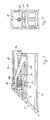
- FIG. 1 and 2 show a first embodiment of a corner connector which comprises a shank 10 which is essentially rectangular in cross section and a welding surface 12 which is inclined at 45 ° to the shank and closes the shank at the left end in FIG. 1.
- the weld surface has a profile that facilitates melting during the welding process and helps to improve the connection.
- a corner connector of this type is inserted, for example, into a reinforcement profile made of metal with a rectangular cross section, which can also be mitered and in turn is inserted into a mitered plastic profile of a door or window. With the help of a welding sword, the corner connector and the plastic profile of the window are welded in one welding process. Details of this type are known and should therefore not be explained in more detail.
- the welding surface 12 protrudes radially in all directions in relation to the shaft 10 and thus simultaneously forms a stop when it is pushed into a reinforcing profile (not shown).
- the shaft 10 has longitudinally directed ribs 14, which can be slightly deformed in the reinforcement profile when non-positively bracing and thus give the seat in the reinforcement tube a certain elasticity.
- the shaft 10 is chamfered on the top in FIGS. 1 and 2, that is to say the shorter, rectangular outside due to the miter, in the direction of the shaft end at an angle of, for example, 20 °.
- the corresponding inclined surface is designated 16.
- the part of the shaft 10 which is omitted due to the bevel is filled by a clamping wedge 18 which is guided on the inclined surface so as to be displaceable with a guide surface 20 which is beveled in accordance with the bevel surface 16.
- guides can be provided on the inclined surface 16 and the guide surface 20, which for example comprise laterally projecting walls 22, 24, which accommodate a lower part 26 of the clamping wedge 18 which is reduced in width.
- the lower part 26 can in turn have webs 28, 30 projecting downward on both lateral edges, which enter into notched grooves in the inclined surface 16.
- the guides formed in this way can also be formed by undercuts or the like so that the shaft 10 and the clamping wedge 18 are slidably connected to one another, but cannot be lost.
- the shaft has cavities 32, 34 in the interior which serve to save material and weight and which are avoided by the build-up of material which is disadvantageous in terms of production technology.
- an axially parallel bore 36 enters the shaft from the welding surface 12 and, starting from the welding surface 12, has a first section 38 of larger diameter and then includes a further section 40 of smaller diameter.
- the bore 36 is arranged so that it merges in the region of the inclined surface 16 from the shaft 10 into the clamping wedge 18 and continues in this in a bore designated 42.
- a further bore 44 runs in the area of the clamping wedge 18 perpendicular to the bore 42 and to the plane of the drawing in FIG. 1.
- the bore 44 receives an anchoring pin 46 which, in the region of the overlap with the bore 42, is provided with a threaded bore, not shown, which is aligned with it is.
- a clamping bolt 48 In the bore 36 of the shaft there is a clamping bolt 48, the head 50 of which is located in the section 38 of larger diameter and is in this way sunk in relation to the welding surface 12.
- the head 50 is supported via a helical spring 52 and an annular disk 54 on a shoulder, not designated, formed between the sections 38 and 40 of the bore 36.
- a bolt shaft 56 of the clamping bolt 48 Within the section 40 of smaller diameter lies in the bore 36 a bolt shaft 56 of the clamping bolt 48, which is on its outer End area is provided with an external thread in a manner not shown. This external thread is screwed into the internal thread of the anchoring pin 46 in the clamping wedge 18.
- the section 40 of the bore 36 has a certain oversize with respect to the bolt shank 56, so that the bolt shank 56 can follow the displacement movement of the clamping wedge 18 and thus the anchoring pin 46 with the threaded bore when the clamping bolt 48 is tightened.
- the clamping wedge can also be provided on an outer surface of the shaft other than that shown, and in principle there is also the possibility of providing more than one clamping wedge on different surfaces, but this will generally be too complex and not necessary.
- FIGS. 3 and 4 show a modified embodiment of the corner connector according to Fig. 1 and 2. After tightening a corner connector and the completion of a window or door frame, it can occasionally by sun exposure or high room temperatures and the associated thermal expansion to such a strong tension between come the corner connector and the hollow profile that there is a risk of damage to the hollow profile.
- the embodiment shown in FIGS. 3 and 4 provides an overload safety device for cases of this type, which enables limited yielding with subsequent renewed locking.
- a recess 58 for example rectangular in cross section, enters the shaft in the vicinity of the bore 36 from the free end and extends to the rear of the welding surface 12.
- An insert 60 of corresponding shape is fitted into this recess 58.
- the bore 36 extends only in part through the welding surface 12 and continues in the insert 60 in the manner already described.
- the recess 58 is arranged so that the inclined surface 16 of the Shafts 10 cuts so that the inclined surface is partially formed by the insert 60.
- the insert 60 has the geometry of the lower region of the lower part 26 of the clamping wedge 18, which has been described in connection with FIGS. 1 and 2.
- a lower part 62 is provided on the clamping wedge 18, which has a lower height and is guided displaceably on the insert 60.
- the insert 60 has on its underside according to FIGS. 1 and 2 a ratchet profile 64 which engages in corresponding grooves (not shown) on the opposite surface of the recess 58.
- the insert 60 Since the insert 60 is fitted relatively closely into the recess 58 and, when the clamping wedge 18 is tensioned, the remaining pressure is exerted on the insert 60 in the direction of engagement of the ratchet profile 64, the insert 60 is adequately fixed in the recess 58 under normal stress.
- Fig. 5 shows schematically an embodiment of the invention, which is particularly suitable for hollow profiles or reinforcing hollow profiles made of metal, which have an uneven or rough inner surface, on which, for example, residues from previous welding or galvanizing work are located.
- the clamping wedge 18 performs a combined radial and axial movement during the clamping process, it is necessary in the final phase of the clamping process that the clamping wedge can move slightly on the inner surface of the hollow profile. If this is not possible due to the impure inner surface of the hollow profile, the entire shaft 10 can pull into the hollow profile 10, for example, and uncontrollable tensions and crushing occur.
- the embodiment shown in FIG. 5 comprises, in addition to the parts described so far, a flat sliding plate 62 which, according to FIG. 5, lies on the upper side of the clamping wedge 18 which is correspondingly reduced in height.
- the sliding plate 62 is supported on the left in FIG. 5 on the back of the welding surface 12, and therefore cannot be pulled to the left together with the clamping wedge 18 during the clamping process.
- the sliding plate 62 consists at least on its lower surface of relatively smooth material with a low coefficient of friction, so that the clamping wedge 18 can easily move over this lower surface.
- the sliding plate 62 can be locked with the aid of suitable projections and recesses (not shown) with the clamping wedge 18 and / or the welding surface 12 while maintaining sufficient freedom of movement.
Landscapes
- Engineering & Computer Science (AREA)
- Mechanical Engineering (AREA)
- Civil Engineering (AREA)
- Structural Engineering (AREA)
- Special Wing (AREA)
- Securing Of Glass Panes Or The Like (AREA)
- Connection Of Plates (AREA)
- Joining Of Corner Units Of Frames Or Wings (AREA)
- Wing Frames And Configurations (AREA)
- Window Of Vehicle (AREA)
Abstract
Description
- Die Erfindung betrifft einen Eckverbinder für Tür- oder Fensterrahmen aus Hohlprofilen, mit einer auf Gehrung verlaufenden Schweißfläche und einem von dieser ausgehenden, dem Innenquerschnitt der zu verbindenden Hohlprofile angepaßten Schaft sowie einer in die Schweißfläche eintretenden, den Eckverbinder parallel zur Längsachse des Hohlprofils durchlaufenden Bohrung zur Aufnahme eines Spannbolzens.
- Ein Eckverbinder dieser Art ist beispielsweise aus dem DE-GM 87 16 578 bekannt. Bei diesem bekannten Eckverbinder weist der Schaft in dem der Schweißfläche gegenüberliegenden Endbereich einander kreuzende Schlitze auf, die sich bis in die axiale Bohrung hinein erstrecken. In die Bohrung wird ein Spreizkonus oder dergleichen eingesetzt, der mit Hilfe eines Bolzens gespannt werden kann. Beim Spreizen werden die einzelnen Segmente unter Verbreiterung der Schlitze auseinandergedrückt, so daß der Eckverbinder kraftschlüssig im Hohlprofil gehalten wird.
- Ein aus dem DE-GM 88 12 423 bekannter Eckverbinder weist in seinem von der Schweißfläche abgewandten Endbereich radiale Führungsschlitze auf, die beispielweise in die Ecken eines rechteckigen Hohlprofils gerichtet sind. In den Führungsschlitzen liegen Lamellen, die mit Hilfe eines im Eckverbinder angeordneten Spreizdübels nach außen gedrückt werden können und den Eckverbinder ebenfalls im Hohlprofil verspannen.
- Lösungen dieser Art sind zwar einwandfrei funktionsfähig, wenn die Abmessungen des Innenquerschnitts des Hohlprofils und des Außenquerschnitts des Eckverbinders ausreichend genau aufeinander abgestimmt sind. Dies ist in der Praxis jedoch nicht immer der Fall. Insbesondere Hohlprofile aus Metall, die als Verstärkungsprofile in Kunststoff-Hohlprofile der Fenster- und Türrahmen eingeschoben werden und ihrerseits den Eckverbinder aufnehmen, können in ihren Abmessungen erheblich schwanken, da die Einhaltung genauerer Toleranzen zu einem vielfach nicht zu vertretenden Mehraufwand führen würde. Ist aber der Innenquerschnitt des Verstärkungsprofils in bezug auf den Außenquerschnitt des Eckverbinders zu weit, so läßt sich dieser zwar in der Regel in seinem von der Schweißfläche abgewandten Endbereich noch ausreichend im Verstärkungsprofil verspannen, wäh rend der der Schweißfläche zugewandte Teil des Schafts in Radialrichtung frei beweglich bleibt.
- Diese verbleibende Beweglichkeit des Eckverbinders im Profil macht die Herstellung einer absolut festen Eckverbindung unmöglich.
- Der Erfindung liegt daher die Aufgabe zugrunde, einen Eckverbinder der gattungsgemäßen Art zu schaffen, der auch bei größeren Abweichungen der Abmessungen des Innenquerschnitts des Hohlprofils und des Außenquerschnitts des Eckverbinders eine feste Verspannung über die gesamte Länge des Eckverbinders ermöglicht.
- Diese Aufgabe wird erfindungsgemäß durch einen Eckverbinder gelöst, der dadurch gekennzeichnet ist, daß der Schaft auf einer Außenfläche in Richtung des von der Schweißfläche abgewandten Endes abgeschrägt ist, daß ein die Abschrägung ausfüllender, auf der Schrägfläche verschiebbar geführter Spannkeil vorgesehen ist, und daß die Bohrung derart angeordnet ist, daß sie die Schrägfläche durchläuft und in die entsprechende Führungsfläche des Spannkeils eintritt.
- Der Spannkeil kann durch Andrehen des Spannbolzen über die Schrägfläche des Schafts in Richtung der Schweißfläche gezogen werden. Dadurch nimmt der Abstand zwischen den einander gegenüberliegenden Außenflächen des Schafts zu, ohne daß diese ihre Parallelität verlieren. Der Schaft wird daher über seine gesamte Länge gleichmäßig zwischen zwei gegenüberliegenden Innenflächen des Hohlprofils verspannt.
- Der Spannkeil kann grundsätzlich auf jeder Außenfläche des Eckverbinders angeordnet sein. Gegebenenfalls ist zu berücksichtigen, daß als Verstärkungsprofile vielfach abgekantete Vierkant-Profile verwendet werden, die an der Nahtstelle nicht verschweißt sind. In diesen Fällen sollte der Spannkeil nicht so angeordnet werden, daß die Naht auseinandergedrückt wird, sondern vielmehr auf der der Naht gegenüberliegenden Seite.
- Der Eckverbinder und der Spannkeil sind vorzugsweise Spritzgu ßteile aus Kunststoff. In dem Spannkeil befindet sich eine Gewindebohrung, in die das Ende des Spannbolzens eintritt. Diese Gewindebohrung liegt vorzugsweise in einem in den Spannkeil eingebetteten Verankerungsteil aus Metall. Die Schrägfläche des Eckverbinders und die Führungsfläche des Spannkeils können korrespondierende Führungen aufweisen. Der Eckverbinder und der Spannkeil können gegebenenfalls auch unverlierbar miteinander verbunden sein.
- Der Kopf des Spannbolzens liegt vorzugsweise versenkt in einem Bohrungs-Abschnitt größeren Durchmessers in dem Eckverbinder. Der Kopf kann sich an der auf diese Weise gebildeten Stufe über eine Druckfeder abstützen, die den Spannbolzen in Zugrichtung vorspannt.
- Bei einer abgewandelten Ausführungsform ist in den Schaft vom Schaftende her eine Ausnehmung eingearbeitet, in die ein verschiebbarer Einsatz eingefügt ist. Die Ausnehmung schneidet die Schrägfläche, und der Einsatz ergänzt diese Schrägfläche mit einem Teil seiner Oberfläche. Der Einsatz nimmt ferner durch eine Bohrung in der Schweißfläche den Bolzen in einer entsprechenden Bohrung auf. Der Einsatz kann in der Ausnehmung durch ein Ratschenprofil in Axialrichtung festgelegt sein, das ein geringfügiges, stufenweises Nachgeben bei Überspannung ermöglicht.
- Bei einer weiteren Ausführungsform der Erfindung, die insbesondere für Hohlprofile mit rauher Innenfläche geeignet ist, befindet sich auf der der Schrägfläche gegenüberliegenden Außenfläche des Spannkeils eine Gleitplatte, die in bezug auf den Spannkeil verschiebbar ist. Die Gleitplatte ermöglicht eine unbehinderte Axialverschiebung des Spannkeils während des Spannvorganges. Bei Hohlprofilen mit rauher Innenfläche besteht die Gefahr, daß sich der Spannkeil beim Spannen in Axialrichtung festsetzt, so daß an seiner Stelle der gesamte Eckverbinder in Axialrichtung gezogen wird und unkontrollierbare Quetsch- und Spannvorgänge entstehen.
- Im folgenden werden bevorzugte Ausführungsbeispiele der Erfindung anhand der beigefügten Zeichnung näher erläutert.
- Fig. 1 ist eine teilweise aufgeschnittene Seitenansicht eines erfindungsgemäßen Eckverbinders;
- Fig. 2 ist eine Stirnansicht von rechts in Fig. 1;
- Fig. 3 ist eine teilweise aufgeschnittene Seitenansicht einer anderen Ausführungsform eines Eckverbinders;
- Fig. 4 zeigt eine Stirnansicht von rechts in Fig. 3;
- Fig. 5 ist eine schematische Seitenansicht einer weiteren Ausführungsform der Erfindung.
- Fig. 1 und 2 zeigen eine erste Ausführungsform eines Eckverbinders, der einen im Querschnitt im wesentlichen rechteckigen Schaft 10 und eine um 45° gegen den Schaft geneigte, den Schaft am linken Ende in Fig. 1 abschließende Schweißfläche 12 umfaßt. Die Schweißfläche weist eine Profilierung auf, die das Schmelzen beim Schweißvorgang erleichtert und zur Verbesserung der Verbindung beiträgt. Ein Eckverbinder dieser Art wird beispielsweise in ein im Querschnitt rechteckiges Verstärkungsprofil aus Metall eingeschoben, das ebenfalls auf Gehrung geschnitten sein kann und seinerseits in ein auf Gehrung geschnittenes Kunststoffprofil einer Tür oder eines Fensters eingeschoben wird. Mit Hilfe eines Schweißschwertes werden der Eckverbinder und das Kunststoffprofil des Fensters in einem Schweißvorgang verschwei ßt. Einzelheiten dieser Art sind bekannt und sollen daher nicht näher erläutert werden. Die Schweißfläche 12 springt in Radialrichtung nach allen Seiten gegenüber dem Schaft 10 vor und bildet somit zugleich einen Anschlag beim Einschieben in ein nicht gezeigtes Verstärkungsprofil.
- Der Schaft 10 weist im dargestellten Beispiel auf den Außenflächenlängsgerichtete Rippen 14 auf, die sich beim kraftschlüssigen Verspannen im Verstärkungsprofil geringfügig verformen lassen und somit dem Sitz im Verstärkungsrohr eine gewisse Elastizität verleihen.
- Der Schaft 10 ist auf der in Fig. 1 und 2 oben liegenden, also der aufgrund der Gehrung kürzeren, rechteckigen Außenseite in Richtung des Schaftendes unter einem Winkel von beispielsweise 20° abgeschrägt. Die entsprechende Schrägfläche ist mit 16 bezeichnet. Der durch die Abschrägung entfallende Teil des Schaftes 10 wird ausgefüllt durch einen Spannkeil 18, der mit einer entsprechend der Schrägfläche 16 abgeschrägten Führungsfläche 20 verschiebbar auf der Schrägfläche geführt ist.
- Zur sicheren Führung des Spannkeils 18 auf dem Schaft 10 können auf der Schrägfläche 16 und der Führungsfläche 20 Führungen vorgesehen sein, die beispielsweise seitlich aufragende Wände 22,24 umfassen, die ein in der Breite verringertes Unterteil 26 des Spannkeils 18 aufnehmen. Das Unterteil 26 kann seinerseits an beiden seitlichen Rändern nach unten vorspringende Stege 28,30 aufweisen, die in nicht bezeichnete Nuten in der Schrägfläche 16 eintreten. Die auf diese Weise gebildete Führungen können auch durch Hinterschneidungen oder dergleichen so ausgebildet sein, daß der Schaft 10 und der Spannkeil 18 verschiebbar, jedoch unverlierbar miteinander verbunden sind.
- Wie Fig. 2 zeigt, weist der Schaft im Inneren Hohlräume 32,34 auf, die der Material- und Cewichtsersparnis dienen und durch die herstellungstechnisch ungünstige Materialanhäufungen vermieden werden.
- In dem durch die Schrägfläche 16 begrenzten, in Fig. 1 oberen, pultförmig aufsteigenden Bereich des Schafts 10 tritt von der Schweißfläche 12 her eine achsparallele Bohrung 36 in den Schaft ein, die, ausgehend von der Schweißfläche 12, einen ersten Abschnitt 38 größeren Durchmessers und anschließend einen weiteren Abschnitt 40 kleineren Durchmessers umfaßt. Die Bohrung 36 ist so angeordnet, daß sie im Bereich der Schrägfläche 16 von dem Schaft 10 in den Spannkeil 18 übergeht und sich in diesem in einer mit 42 bezeichneten Bohrung fortsetzt.
- Eine weitere Bohrung 44 verläuft im Bereich des Spannkeils 18 senkrecht zur Bohrung 42 und zur Zeichenebene in Fig. 1. Die Bohrung 44 nimmt einen Verankerungsstift 46 auf, der im Bereich der Überschneidung mit der Bohrung 42 mit einer mit dieser fluchtenden, nicht gezeigten Gewindebohrung versehen ist.
- In der Bohrung 36 des Schafts liegt ein Spannbolzen 48, dessen Kopf 50 sich im Abschnitt 38 größeren Durchmessers befindet und auf diese Weise in bezug auf die Schweißfläche 12 versenkt ist. Der Kopf 50 stützt sich über eine Schraubenfeder 52 und eine Ringscheibe 54 an einer zwischen den Abschnitten 38 und 40 der Bohrung 36 gebildeten, nicht bezeichneten Schulter ab. Innerhalb des Abschnitts 40 geringeren Durchmessers liegt in der Bohrung 36 ein Bolzenschaft 56 des Spannbolzen 48, der an seinem äußeren Endbereich in nicht gezeigter Weise mit einem Au ßengewinde versehen ist. Dieses Außengewinde wird in das Innengewinde des Verankerungsstifts 46 in dem Spannkeil 18 eingeschraubt.
- Der Abschnitt 40 der Bohrung 36 weist gegenüber dem Bolzenschaft 56 ein gewisses Übermaß auf, so daß der Bolzenschaft 56 beim Anziehen des Spannbolzens 48 der Verschiebebewegung des Spannkeils 18 und damit des Verankerungsstifts 46 mit der Gewindebohrung folgen kann.
- Beim Anziehen des Spannbolzens 48 bleibt die Parallelität zwischen den oberen und unteren Oberflächen des Schaftes 10 und Spannkeils 18 erhalten, so daß der Schaft über die gesamt Länge des Spannkeils 18 im Hohlprofil gleichmäßig verspannt wird.
- Wie bereits erwähnt, kann der Spannkeil auch auf einer anderen als der gezeigten Außenfläche des Schafts vorgesehen sein, und grundsätzlich besteht auch die Möglichkeit, mehr als einen Spannkeil auf verschiedenen Oberflächen vorzusehen, jedoch wird dies in der Regel zu aufwendig und nicht erforderlich sein.
- Fig. 3 und 4 zeigen eine abgewandelte Ausführungsform des Eckverbinders gemäß Fig. 1 und 2. Nach dem Verspannen eines Eckverbinders und der Fertigstellung eines Fenster- oder Türrahmens kann es gelegentlich durch Sonneneinstrahlung oder hohe Raumtemperaturen und die damit verbundene Wärmedehnung zu einer so starken Spannung zwischen dem Eckverbinder und dem Hohlprofil kommen, daß die Gefahr einer Beschädigung des Hohlprofils besteht. Die in Fig. 3 und 4 dargestellte Ausführungsform sieht für Fälle dieser Art eine Überlastsicherung vor, die ein begrenztes Nachgeben mit anschließender erneuter Verrastung ermöglicht.
- Zu diesem Zweck tritt vom freien Ende her in den Schaft in der Umgebung der Bohrung 36 eine im Querschnitt beispielsweise rechteckige Ausnehmung 58 ein, die sich bis zur Rückseite der Schweißfläche 12 erstreckt. In diese Ausnehmung 58 ist ein Einsatz 60 entsprechender Form eingepaßt. Die Bohrung 36 erstreckt sich nur zu einem Teil durch die Schweißfläche 12 und setzt sich im übrigen in dem Einsatz 60 in der bereits beschriebenen Weise fort. Die Ausnehmung 58 ist so angeordnet, daß sie die Schrägfläche 16 des Schafts 10 schneidet, so daß die Schrägfläche zum Teil durch den Einsatz 60 gebildet wird.
- Wie Fig. 4 zeigt, weist der Einsatz 60 die Geometrie des unteren Bereichs des Unterteils 26 des Spannkeils 18 auf, das im Zusammenhang mit Fig. 1 und 2 beschrieben worden ist. Bei der Ausführungsform gemäß Fig. 3 und 4 ist ein Unterteil 62 an dem Spannkeil 18 vorgesehen, das eine geringere Höhe besitzt und auf dem Einsatz 60 verschiebbar geführt ist. Der Einsatz 60 weist an seiner Unterseite gemäß Fig. 1 und 2 ein Ratschenprofil 64 auf, das in entsprechende, nicht gezeigte Rillen auf der gegenüberliegenden Oberfläche der Ausnehmung 58 eingreift. Da der Einsatz 60 verhältnismäßig eng in die Ausnehmung 58 eingepaßt ist und beim Spannen des Spannkeils 18 im übrigen Druck in Eingriffsrichtung des Ratschenprofils 64 auf den Einsatz 60 ausgeübt wird, ist der Einsatz 60 in der Ausnehmung 58 bei normaler Beanspruchung ausreichend festgelegt.
- Im Falle einer überhöhten Belastung des gespannten Eckverbinders durch Kräfte, die von oben und unten in Fig. 3 auf den Schaft bzw. den Spannkeil 18 einwirken, weisen die von oben auf den Spannkeil 18 gerichteten Kräfte einen Kraftvektor auf, der bestrebt ist, den Spannkeil über die Führungen nach rechts in Fig. 3 zurückzuschieben. Dies führt zu einer nach rechts in Fig. 3 gerichteten Zugwirkung, die sich über den Spannbolzen 48 auf den Einsatz 60 überträgt. Überschreitet diese Zugwirkung ein vorgegebenes Maß, so kann das Ratschenprofil 64 um einen oder wenige Zähne nachgeben und bei Nachlassen der Belastung wieder einrasten. Die Schraubenfeder 52, die auch bei der Ausführungsform gemäß Fig. 1 vorgesehen ist, führt in jedem Falle zu einer ausreichenden Vorspannung des Spannbolzens und damit einer ausreichenden Festlegung des Spannkeils 18. Zur Erleichterung des Zurückziehens des Einsatzes 60 in den zuvor geschilderten Fällen kann dieser Einsatz an der unteren Oberfläche, ebenso wie die entsprechende obere Oberfläche der Ausnehmung 58, nach rechts in Fig. 3 geringfügig geneigt sein.
- Fig. 5 zeigt schematisch eine Ausführungsform der Erfindung, die insbesondere geeignet ist für Hohlprofile oder Verstärkungs-Hohlprofile aus Metall, die eine unebene oder rauhe Innenfläche aufweisen, an denen sich beispielsweise Rückstände von zurückliegenden Schweiß- oder Verzinkungsarbeiten befinden. Da der Spannkeil 18 beim Spannvorgang eine kombinierte Radial- und Axialbewegung ausführt, ist es in der Endphase des Spannvorganges erforderlich, daß sich der Spannkeil geringfügig auf der Innenfläche des Hohlprofils verschieben kann. Ist dies wegen unreiner Innenfläche des Hohlprofils nicht möglich, so kann sich beispielsweise der gesamte Schaft 10 in das Hohlprofil 10 hineinziehen, und es kommt zu unkontrollierbaren Verspannungen und Verquetschungen.
- Die in Fig. 5 gezeigte Ausführungsform umfaßt zusätzlich zu den bisher beschriebenen Teilen eine flache Gleitplatte 62, die gemäß Fig. 5 auf der Oberseite des entsprechend in der Höhe verringerten Spannkeils 18 liegt. Die Gleitplatte 62 stützt sich nach links in Fig. 5 an der Rückseite der Schweißfläche 12 ab, kann also beim Spannvorgang nicht zusammen mit dem Spannkeil 18 nach links gezogen werden. Die Gleitplatte 62 besteht zumindest auf ihrer unteren Oberfläche aus verhältnismäßig glattem Material mit geringem Reibungskoeffizienten, so daß sich der Spannkeil 18 leicht über diese untere Oberfläche verschieben kann.
- Zur unverlierbaren Verbindung mit dem übrigen Eckverbinder kann die Gleitplatte 62 mit Hilfe geeigneter, nicht gezeigter Vorsprünge und Ausnehmungen mit dem Spannkeil 18 und/oder der Schweißfläche 12 unter Beibehaltung eines ausreichenden Bewegungsspielraums verrastet sein.
Claims (8)
Applications Claiming Priority (2)
| Application Number | Priority Date | Filing Date | Title |
|---|---|---|---|
| DE8910401U | 1989-08-31 | ||
| DE8910401U DE8910401U1 (de) | 1989-08-31 | 1989-08-31 | Eckverbinder für Tür- oder Fensterrahmen |
Publications (3)
| Publication Number | Publication Date |
|---|---|
| EP0415394A2 true EP0415394A2 (de) | 1991-03-06 |
| EP0415394A3 EP0415394A3 (en) | 1991-09-25 |
| EP0415394B1 EP0415394B1 (de) | 1993-05-26 |
Family
ID=6842439
Family Applications (1)
| Application Number | Title | Priority Date | Filing Date |
|---|---|---|---|
| EP90116585A Expired - Lifetime EP0415394B1 (de) | 1989-08-31 | 1990-08-29 | Eckverbinder für Tür- oder Fensterrahmen |
Country Status (4)
| Country | Link |
|---|---|
| EP (1) | EP0415394B1 (de) |
| AT (1) | ATE89895T1 (de) |
| DE (2) | DE8910401U1 (de) |
| DK (1) | DK0415394T3 (de) |
Cited By (6)
| Publication number | Priority date | Publication date | Assignee | Title |
|---|---|---|---|---|
| DE4215661C1 (en) * | 1992-05-13 | 1993-07-01 | Grotefeld, Monika, 4970 Bad Oeynhausen, De | Corner connector for door or window frame - has welding surface running on mitring and shaft evolving from welding surface and matching inner cross=section of hollow profiles to be joined |
| DE4319125A1 (de) * | 1993-06-09 | 1994-12-15 | Hartman Groep Bv | Standmöbel mit längenverstellbaren Beinen und die Längenverstellbarkeit ermöglichenden Haltefüßen |
| EP0698720B1 (de) * | 1994-08-22 | 1999-09-01 | PHI Reichel GmbH | Verfahren zum Befestigen von Eckverbindern, vorzugsweise aus verschweissbarem Kunststoff, und Eckverbinder zur Verwendung bei einem solchen Verfahren |
| EP1054130A3 (de) * | 1999-05-18 | 2002-08-14 | Hans Dieter Grotefeld | Verfahren zum Festlegen eines Eckverbinders in einem Tür- oder Fenster-Hohlprofil sowie Eckverbinder und Werkzeug zu dessen Durchführung |
| CN103510808A (zh) * | 2012-06-25 | 2014-01-15 | 汉斯·迪特尔·格罗特菲尔德 | 用于空心型材框架的拐角连接件 |
| DE202022106054U1 (de) | 2022-10-27 | 2022-11-10 | Ćamil Sulejmanagić | Eckverbinder |
Families Citing this family (12)
| Publication number | Priority date | Publication date | Assignee | Title |
|---|---|---|---|---|
| DE9014643U1 (de) * | 1990-10-23 | 1991-01-24 | Niemann, Hans Dieter, 5014 Kerpen | Eckschweißverbinder zum Verbinden zweier auf Gehrung geschnittener Hohlkammerprofile |
| FR2683006B3 (fr) * | 1991-10-24 | 1993-09-17 | Phi Reichel Gmbh | Connecteur d'angle. |
| DE10039403C1 (de) | 2000-08-11 | 2001-12-13 | Reichel Phi Gmbh | Eckverbinder |
| DE10210309B4 (de) * | 2002-03-08 | 2004-01-29 | Phi Reichel Gmbh | Eckverbinder |
| DE102004015373B3 (de) | 2004-03-26 | 2006-01-05 | Hans Dieter Grotefeld | Eckverbinder für Fenster, Türen usw. aus Kunstoff-Hohlprofilen |
| DE102006001045B4 (de) * | 2006-01-07 | 2008-11-13 | Hans Dieter Grotefeld | Eckverbinder für Tür- oder Fensterrahmen |
| DE102007030619B4 (de) | 2007-07-02 | 2010-10-07 | Hans Dieter Grotefeld | Eckverbinder für Tür- und Fensterrahmen |
| DE102007030618B3 (de) * | 2007-07-02 | 2009-03-05 | Hans Dieter Grotefeld | Eckverbinder für Tür- und Fensterrahmen |
| DE102007030616B4 (de) | 2007-07-02 | 2009-06-10 | Hans Dieter Grotefeld | Eckverbinder für Tür- und Fensterrahmen |
| DE102007030617B4 (de) | 2007-07-02 | 2009-05-20 | Hans Dieter Grotefeld | Eckverbinder für Tür- und Fensterrahmen |
| DE102009048140A1 (de) | 2009-10-02 | 2011-04-07 | Grotefeld Kunststofftechnik Gmbh | Eckverbinder sowie Verfahren und Vorrichtung zu deren Montage |
| DE102016104889B4 (de) | 2016-03-16 | 2017-11-23 | PHI Technik für Fenster und Türen GmbH | Eckverbinder |
Family Cites Families (3)
| Publication number | Priority date | Publication date | Assignee | Title |
|---|---|---|---|---|
| DE2755917A1 (de) * | 1977-12-15 | 1979-06-21 | Erwin Bergmann | Metall-profilleiste mit thermischer unterbrechung, insbesondere fuer fenster, tueren oder dergleichen |
| DE3712478C1 (de) * | 1987-04-13 | 1988-11-03 | Huels Troisdorf | Eckverbinder zum Verbinden zweier auf Gehrung geschnittener Hohlkammerprofile |
| DE8812423U1 (de) * | 1988-10-01 | 1988-11-17 | Grotefeld, Hans Dieter, 4970 Bad Oeynhausen | Eckverbinder für Tür- oder Fensterrahmen |
-
1989
- 1989-08-31 DE DE8910401U patent/DE8910401U1/de not_active Expired
-
1990
- 1990-08-29 DK DK90116585.2T patent/DK0415394T3/da active
- 1990-08-29 DE DE9090116585T patent/DE59001545D1/de not_active Expired - Lifetime
- 1990-08-29 EP EP90116585A patent/EP0415394B1/de not_active Expired - Lifetime
- 1990-08-29 AT AT90116585T patent/ATE89895T1/de not_active IP Right Cessation
Cited By (8)
| Publication number | Priority date | Publication date | Assignee | Title |
|---|---|---|---|---|
| DE4215661C1 (en) * | 1992-05-13 | 1993-07-01 | Grotefeld, Monika, 4970 Bad Oeynhausen, De | Corner connector for door or window frame - has welding surface running on mitring and shaft evolving from welding surface and matching inner cross=section of hollow profiles to be joined |
| DE4319125A1 (de) * | 1993-06-09 | 1994-12-15 | Hartman Groep Bv | Standmöbel mit längenverstellbaren Beinen und die Längenverstellbarkeit ermöglichenden Haltefüßen |
| EP0698720B1 (de) * | 1994-08-22 | 1999-09-01 | PHI Reichel GmbH | Verfahren zum Befestigen von Eckverbindern, vorzugsweise aus verschweissbarem Kunststoff, und Eckverbinder zur Verwendung bei einem solchen Verfahren |
| EP1054130A3 (de) * | 1999-05-18 | 2002-08-14 | Hans Dieter Grotefeld | Verfahren zum Festlegen eines Eckverbinders in einem Tür- oder Fenster-Hohlprofil sowie Eckverbinder und Werkzeug zu dessen Durchführung |
| CN103510808A (zh) * | 2012-06-25 | 2014-01-15 | 汉斯·迪特尔·格罗特菲尔德 | 用于空心型材框架的拐角连接件 |
| CN103510808B (zh) * | 2012-06-25 | 2016-09-14 | 汉斯·迪特尔·格罗特菲尔德 | 用于空心型材框架的拐角连接件 |
| DE202022106054U1 (de) | 2022-10-27 | 2022-11-10 | Ćamil Sulejmanagić | Eckverbinder |
| EP4365399A1 (de) | 2022-10-27 | 2024-05-08 | Camil Sulejmanagic | Eckverbinder |
Also Published As
| Publication number | Publication date |
|---|---|
| DE8910401U1 (de) | 1989-10-26 |
| EP0415394A3 (en) | 1991-09-25 |
| DE59001545D1 (de) | 1993-07-01 |
| DK0415394T3 (da) | 1993-06-21 |
| ATE89895T1 (de) | 1993-06-15 |
| EP0415394B1 (de) | 1993-05-26 |
Similar Documents
| Publication | Publication Date | Title |
|---|---|---|
| EP0415394B1 (de) | Eckverbinder für Tür- oder Fensterrahmen | |
| DE2618442C2 (de) | Stütze für ein Geländer oder dergleichen | |
| EP1259738B1 (de) | Profilverbindungseinrichtung | |
| EP0288756B1 (de) | Eckverbinder zum Verbinden zweier auf Gehrung geschnittener Hohlkammerprofile | |
| DE69104754T2 (de) | Blindbefestiger mit einer doppelten Verriegelung. | |
| DE3843096C2 (de) | Befestigungseinrichtung für Verkleidungen | |
| EP1135616A1 (de) | T-verbindung zweier profilstäbe | |
| DD237534A5 (de) | Duebel | |
| DE3328142A1 (de) | Konstruktion aus profilstaeben | |
| EP1055073A2 (de) | Verbindungsvorrichtung für flächige körper oder sonstige bauteile | |
| EP2706185A1 (de) | Verfahren und Anordnung zum Befestigen eines Pfostens an einer Rahmenleiste eines Fensters oder einer Türe mittels eines Pfostenverbinders | |
| EP0004374A1 (de) | Vorrichtung zum Verbinden von zwei Profilstäben | |
| DE20019594U1 (de) | Justiervorrichtung eines Rahmens | |
| DE19522044A1 (de) | Eck- oder T-Verbindung an Rahmen oder Gestellen | |
| EP1915539B1 (de) | Kippverbinder | |
| DE69410982T2 (de) | Stellbare Vorrichtung, insbesondere für Metallrahmen | |
| EP0371237B1 (de) | Bausatz für eine Türzarge | |
| DE2606940A1 (de) | Befestigungsmittel | |
| DE4213862A1 (de) | Blindnietartiger Klemmverbinder | |
| EP2679759B1 (de) | Eckverbinder für Hohlprofilrahmen | |
| EP0291973B1 (de) | Verbindungsstück für zwei winklig aneinanderstossende Profilstäbe von Fenster oder Türrahmen | |
| DE4039421C2 (de) | ||
| EP0382081B1 (de) | Bolzen zum Verbinden von Bauteilen mit Wandflächen | |
| EP1178225A1 (de) | Verbindungselement zur Herstellung einer Stoss- oder Eckverbindung | |
| DE29910962U1 (de) | Befestigungsvorrichtung zum Verbinden von Rahmenprofilen |
Legal Events
| Date | Code | Title | Description |
|---|---|---|---|
| PUAI | Public reference made under article 153(3) epc to a published international application that has entered the european phase |
Free format text: ORIGINAL CODE: 0009012 |
|
| AK | Designated contracting states |
Kind code of ref document: A2 Designated state(s): AT BE CH DE DK ES FR GB IT LI NL |
|
| PUAL | Search report despatched |
Free format text: ORIGINAL CODE: 0009013 |
|
| AK | Designated contracting states |
Kind code of ref document: A3 Designated state(s): AT BE CH DE DK ES FR GB IT LI NL |
|
| 17P | Request for examination filed |
Effective date: 19920318 |
|
| 17Q | First examination report despatched |
Effective date: 19921104 |
|
| GRAA | (expected) grant |
Free format text: ORIGINAL CODE: 0009210 |
|
| AK | Designated contracting states |
Kind code of ref document: B1 Designated state(s): AT BE CH DE DK ES FR GB IT LI NL |
|
| PG25 | Lapsed in a contracting state [announced via postgrant information from national office to epo] |
Ref country code: ES Free format text: THE PATENT HAS BEEN ANNULLED BY A DECISION OF A NATIONAL AUTHORITY Effective date: 19930526 |
|
| REF | Corresponds to: |
Ref document number: 89895 Country of ref document: AT Date of ref document: 19930615 Kind code of ref document: T |
|
| REG | Reference to a national code |
Ref country code: DK Ref legal event code: T3 |
|
| REF | Corresponds to: |
Ref document number: 59001545 Country of ref document: DE Date of ref document: 19930701 |
|
| ET | Fr: translation filed | ||
| ITF | It: translation for a ep patent filed | ||
| GBT | Gb: translation of ep patent filed (gb section 77(6)(a)/1977) |
Effective date: 19930624 |
|
| PLBE | No opposition filed within time limit |
Free format text: ORIGINAL CODE: 0009261 |
|
| STAA | Information on the status of an ep patent application or granted ep patent |
Free format text: STATUS: NO OPPOSITION FILED WITHIN TIME LIMIT |
|
| 26N | No opposition filed | ||
| REG | Reference to a national code |
Ref country code: GB Ref legal event code: IF02 |
|
| PGFP | Annual fee paid to national office [announced via postgrant information from national office to epo] |
Ref country code: FR Payment date: 20090730 Year of fee payment: 20 Ref country code: DK Payment date: 20090813 Year of fee payment: 20 |
|
| PGFP | Annual fee paid to national office [announced via postgrant information from national office to epo] |
Ref country code: NL Payment date: 20090729 Year of fee payment: 20 Ref country code: AT Payment date: 20090820 Year of fee payment: 20 Ref country code: CH Payment date: 20090827 Year of fee payment: 20 Ref country code: DE Payment date: 20090828 Year of fee payment: 20 Ref country code: GB Payment date: 20090807 Year of fee payment: 20 |
|
| PGFP | Annual fee paid to national office [announced via postgrant information from national office to epo] |
Ref country code: BE Payment date: 20090817 Year of fee payment: 20 |
|
| PGFP | Annual fee paid to national office [announced via postgrant information from national office to epo] |
Ref country code: IT Payment date: 20090820 Year of fee payment: 20 |
|
| BE20 | Be: patent expired |
Owner name: *GROTEFELD HANS DIETER Effective date: 20100829 |
|
| REG | Reference to a national code |
Ref country code: CH Ref legal event code: PL |
|
| REG | Reference to a national code |
Ref country code: NL Ref legal event code: V4 Effective date: 20100829 |
|
| REG | Reference to a national code |
Ref country code: DK Ref legal event code: EUP |
|
| REG | Reference to a national code |
Ref country code: GB Ref legal event code: PE20 Expiry date: 20100828 |
|
| PG25 | Lapsed in a contracting state [announced via postgrant information from national office to epo] |
Ref country code: NL Free format text: LAPSE BECAUSE OF EXPIRATION OF PROTECTION Effective date: 20100829 |
|
| PG25 | Lapsed in a contracting state [announced via postgrant information from national office to epo] |
Ref country code: GB Free format text: LAPSE BECAUSE OF EXPIRATION OF PROTECTION Effective date: 20100828 |
|
| PG25 | Lapsed in a contracting state [announced via postgrant information from national office to epo] |
Ref country code: DE Free format text: LAPSE BECAUSE OF EXPIRATION OF PROTECTION Effective date: 20100829 |