EP0415333A2 - Steuerseil - Google Patents
Steuerseil Download PDFInfo
- Publication number
- EP0415333A2 EP0415333A2 EP90116419A EP90116419A EP0415333A2 EP 0415333 A2 EP0415333 A2 EP 0415333A2 EP 90116419 A EP90116419 A EP 90116419A EP 90116419 A EP90116419 A EP 90116419A EP 0415333 A2 EP0415333 A2 EP 0415333A2
- Authority
- EP
- European Patent Office
- Prior art keywords
- liner
- control cable
- outer spring
- string
- low melting
- Prior art date
- Legal status (The legal status is an assumption and is not a legal conclusion. Google has not performed a legal analysis and makes no representation as to the accuracy of the status listed.)
- Granted
Links
Images


Classifications
-
- F—MECHANICAL ENGINEERING; LIGHTING; HEATING; WEAPONS; BLASTING
- F16—ENGINEERING ELEMENTS AND UNITS; GENERAL MEASURES FOR PRODUCING AND MAINTAINING EFFECTIVE FUNCTIONING OF MACHINES OR INSTALLATIONS; THERMAL INSULATION IN GENERAL
- F16C—SHAFTS; FLEXIBLE SHAFTS; ELEMENTS OR CRANKSHAFT MECHANISMS; ROTARY BODIES OTHER THAN GEARING ELEMENTS; BEARINGS
- F16C1/00—Flexible shafts; Mechanical means for transmitting movement in a flexible sheathing
- F16C1/26—Construction of guiding-sheathings or guiding-tubes
-
- F—MECHANICAL ENGINEERING; LIGHTING; HEATING; WEAPONS; BLASTING
- F16—ENGINEERING ELEMENTS AND UNITS; GENERAL MEASURES FOR PRODUCING AND MAINTAINING EFFECTIVE FUNCTIONING OF MACHINES OR INSTALLATIONS; THERMAL INSULATION IN GENERAL
- F16C—SHAFTS; FLEXIBLE SHAFTS; ELEMENTS OR CRANKSHAFT MECHANISMS; ROTARY BODIES OTHER THAN GEARING ELEMENTS; BEARINGS
- F16C1/00—Flexible shafts; Mechanical means for transmitting movement in a flexible sheathing
- F16C1/10—Means for transmitting linear movement in a flexible sheathing, e.g. "Bowden-mechanisms"
- F16C1/20—Construction of flexible members moved to and fro in the sheathing
Definitions
- the present invention relates to a control cable, and more particularly, to a control cable in which a liner is to be prevented from shrinking, and operating feeling is good, and besides, the liner is not easily slipped out of an outer spring.
- a control cable comprises a conduit and an inner core or inner cable, and is a means for remotely controlling an object to be controlled by pulling, by pushing and pulling or by rotating the inner cable.
- the above-mentioned conduit generally comprises what is called an armour or outer spring and an outer coat.
- the outer spring is made by roll-forming a steel wire to a flat strip and then by winding in abutting convolutions to form a coiled spring.
- Another type of conduit comprises plural steel wires which are laid side by side and wound helically to form a tubular member.
- the outer coat is a layer of plastic materials which covers and protects the outside surface of the conduit.
- the inner cable which is inserted into the above-mentioned conduit comprises a stranded wires obtained by twisting plural wires or strands which are mutually twisted.
- a tubular liner 3 is set at the inside surface of the outer spring 4 in order to reduce the friction and the abrasion.
- the tubular liner is generally made of plastics of which coefficient of friction is low and abrasion resistance is superior.
- the tubular liner can be closely set in the outer spring by winding a flat steel strip around the outside surface of the liner so that the liner is wrapped in the outer spring, or by inserting the liner into the conduit after the outer spring is formed in a coiled-shape.
- a clearance more than 0.5 mm between the control cable and the outer spring is required in a state that a liner is inserted into the outer spring.
- it is necessary to provide an additional mechanism so that the liner is not easy to slip out for example, by making a flare portion at an end of the liner, or by putting a washer between the end of conduit and a member (e.g. cap member) to which the end of conduit is fixed.
- the object of the present invention is to delete the above-mentioned disadvantages of the conventional control cable and to provide a control cable in which reversible thermal expansion and contraction of the liner is not hindered by the outer spring hence a liner is prevented from successive shrinking, the unevenness and roughness does not come out on the inside surface of the liner, and further, the liner is not easy to be slipped out of an outer spring without employing any special mechanism.
- the control cable of the present invention comprises an inner cable, a conduit and a liner for slidably guiding the inner cable.
- the conduit has an outer spring made of a coiled steel strip and an outer coat made of synthetic resin formed on the outside surface of the outer spring.
- the liner is set between the above-mentioned conduit and the inner cable with remaining a clearance between the above-mentioned outer spring and the liner, and an interposition is provided in the clearance.
- the interposition is set in order to keep a suitable clearance and to provide a suitable resistance for a relative motion between the liner and the outer spring so that a thermal expansion and contraction of the liner is not hindered and nevertheless the liner cannot easily slip out of the outer spring.
- the clearance is provided between the outer spring and the liner, and further, the specified interposition is set in the clearance, thermal expansion of the liner is not hindered when the control cable is heated. Therefore, the liner is able to be prevented from successive and irreversible shrinking when the control cable is repeatedly heated and cooled.
- control cable since the control cable has the clearance between the outer spring and the liner, the unevenness of the outer spring does not come out on the inside surface of the liner, and the inside surface is kept smooth in any cable arrangement. Therefore, the operating feeling of the control cable becomes better as compared with a conventional control cable. Further, since the interposition is inserted in the clearance, the liner is not easy to be slipped out from the outer spring.
- a foamed material is used as the above-mentioned interposition.
- the foamed material provides an advantage, for example, that the heat expansion (or shrinkage) is absorbed due to the shrinkage (or expansion) of the formed material itself.
- a low melting-(or softening)-point material such as wax or resin used as the above-mentioned interposition.
- the low melting-point material is preferably laid intermittently on the liner. However, the material can be extended continuously along the liner.
- the melting point or the softening point is preferably in a range from 40 to 100°C.
- the liner is not prevented from free thermal expansion since the low melting-point material is melted or softened at elevated temperature.
- a string-like member is interposed between the outer spring and the liner as the interposition or a spacer.
- At least one string-like member should be spirally wound around the liner or linearly extended along the liner. Further, in both cases, plural members can be used, and a combination of spirally wound member and a linearly extending member can be used. For example, a string-like member can be spirally wound around a liner with another linearly extending string-like member.
- a twisted thread As the string-like member, a twisted thread, a continuous long untwisted bundle of multi-filaments or mono-filament, or a tube can be employed.
- the string-like member is preferably a twisted thread impregnated with low melting-point material.
- a thread, filaments or a tube coated with the low melting-point material is also preferably employed as the string-like member.
- control cable of the present invention has, for example a construction shown in Fig. 1.
- control cable of the present invention is not limited to the shape of Fig. 1.
- the control cable 1 of Fig. 1 comprises a conduit 6.
- the conduit 6 comprises an outer spring 4 which is a steel wire roll-formed such that the cross section becomes flat, and then spirally wound, and an outer coat 5 made of synthetic resin.
- the coat 5 is formed around the outside surface of the outer spring.
- the control cable 1 includes further a tubular liner 3 which is made of synthetic resin with small coefficient of friction and superior abrasion resistance.
- the liner 3 is provided in the outer spring of the abovementioned conduit 6 with remaining a clearance B.
- an inner core or inner cable 2 is slidably inserted through the conduit 6, i.e. through the liner 3.
- the inner cable 2 is generally made of plural steel wires which are mutually twisted.
- a foamed material A1 is set in the clearance B between the abovementioned outer spring 4 and the liner 3 as the interposition.
- the foamed material A1 is substantially straight and extends along the liner 3 in the axial direction.
- the linear foamed material A1 might be two or more.
- the foamed material A1 is not only set straightly but also might be wound spirally around the liner 3.
- the foamed material A2 has a tubular shape such that the liner 3 is covered with the foamed material A2.
- the foamed material A2 might be also filled between the liner 3 and the outer spring 4.
- foamed material A1 examples include polyurethane, polyethylene, polypropylene, neopren, chloroprene, polystyrene, phenol, polyurea, polyvinyl chloride and the like.
- the foamed material might be not only a open cell foam but also a closed cell foam. Expansion ratio of the foamed material is preferably 150 - 800 % and more preferably 200 - 500 %.
- the material of the liner 3 tetrafluoroethylene/hexafluoropropylene copolymer polyacetal, and the like might be preferably employed. However, in the present invention, the material of the liner 3 is not limited to the above-mentioned polymer.
- the foamed material can be set between the outer spring and the liner continuously, intermittently on the liner 3. Further, a combination of continuously extending foamed material and intermittently extending foamed materials can also be used.
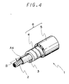
- a control cable 1 shown in Figs. 3 and 4 is the same as the control cable 1 shown in Fig. 1 except that low melting-point materials A3, A4 are set between the outer spring 4 and the liner 3.
- paraffin wax, saturated copolyesters, olefine copolymers for example, ethylene-vinylacetate copolymer, ethylene-ethylacrylate copolymer
- hot melt adhesives for example, plasticized compounds based on ethylene-vinylacetate copolymer, atactic polypropylene, copolyesters, synthetic rubbers
- the material is not limited to the above-mentioned wax and resins, and another thermoplastic resins with low melting (or softening) point are able to be used.
- the above-mentioned low melting-point material is set as an interposition intermittently (see Fig. 3) or continuously (see Fig. 4) provided material or a combination of intermittently provided material and continuously provided material, before the outer spring 4 is wound around the liner 4.
- the thickness of the above-mentioned material is not less than double of the clearance between the above-mentioned outer spring 4 and the liner 3, the material is melted or softened with heat, when the outer spring 4 is closely wound around the liner 3. Then, the resin advantageously is left as a film or a coat.
- the preferable range of the melting point or the softening point of the material is 40 to 100°C. That is to say, in case that the melting point or softening point is more than 100°C, the material dropped on the liner 3 is not melted or softened with heat when the heated steel strip is closely coiled around the liner 3 to form an outer spring.
- the outer spring 4 is pushed on the liner 3, and the unevenness tends to come out on the inside face of the liner 3.
- melting point or softening point is not larger than 40°C, the fixing force (adhesive force) between the low melting material and the liner 3 can be inferior.
- the above-mentioned melting point is the temperature in which a solid becomes liquid by absorbing heat under a condition that a pressure is applied
- the above-mentioned softening point is the temperature in which a material becomes soft and a mechanical property (strength, or the like) of the material becomes low.
- the measuring methods for determining the melting point and the softening point are described hereinbelow.
- the melting point can be determined, for example, in accordance with "method of measuring a transition point of a plastic in The Ameriacan Society for Testing and Materials (ASTM D 3418)". That is, at first a differential scanning calorimetry is performed, and melting temperature is found. Then the temperature is determined as the melting point of the material.
- the softening point can be determined, for example, in accordance with ring and ball method (ASTM D 36-86,ASTM E28-67). That is to say, a melted sample is poured into a brass ring having a predetermined size, and then is cured. Next, a steel ball having a constant volume is put on the cured sample. Then, by heating the sample in a heated oil tank, the temperature when the ball drops through the sample is determined as the softening point.
- Conduits 6, inner cables 2 and liners 3 of the control cables 1 of Figs. 5 to 7 are fundamentally the same as the control cables shown in Figs. 1 and 2.
- Each of the string-like members A5, A6 and A7 is set between the above-mentioned outer spring 4 and the liner 3 as an interposition.
- the string-like member might be not only wound spirally on the outside surface of the liner 3 as shown in Figs. 5 and 7, but also might be set rectilinearly along the liner 3 as shown in Fig. 6.
- the above-mentioned string-like member is able to be formed spirally and linearly.
- a twisted thread or thread plying A5 of Fig. 5
- a bundle of filaments A6 of Fig. 6
- a tube A7 of Fig. 7
- the material of the thread are, polyester, cotton yarn, and the like.
- the materials of the filament and the tube are a plastic (e.g. polyester, polyethylene, polyamide, polyacetal), thermoplastic elastomer (e.g.
- polyurethane polyolefine elastomer, polyester elastomer, polyamide elastomer, polyvinylchroride elastomer, styrene elastomer, nitrile elastomer, chrorinated polyethylene) and a rubber material (ethylen-propylene rubber, butyl rubber, silicone rubber, urethane rubber, natural rubber).
- a rubber material ethylen-propylene rubber, butyl rubber, silicone rubber, urethane rubber, natural rubber.
- the diameter of the above-mentioned string-like member is preferably 1.2 to 3 times of the dimension of the clearance B between an outer spring 4 and a liner 3. That is to say, when the diameter is less than 1.2 times of the clearance B, the liner 3 is respectively easily slipped out of the outer spring. On the contrary, when the diameter is more than three times of the clearance B, the unevenness tends to come out on the inside surface of the liner, since the liner 3 is abutted against the outer spring.
- the diameter of the string-like member preferably has a diameter of 1 to 2 times of the clearance.
- the diameter is less than the clearance B, the liner 3 tends to easily slip out of the outer spring 4, and when the diameter is more than the double clearance B, the unevenness tends to come out on the inside surface of the liner 3 since the liner 3 is compressed by the outer spring 4.
- the inside diameter of the tube has a value not less than the remainder obtained by subtracting the clearance from the diameter.
- the inside diameter is less than the remainder, the unevenness tends to come out on the inside surface of the liner since the tube A3 is lacking in the deformation quantity. That is to say, even if the inside diameter of the tube is squeezed, the outer spring clamps the tube more than the squeezed dimension, since the thickness of tube is larger than the clearance.
- the above-mentioned twisted thread A5, the filament A6 and the tube A7 are preferably impregnated or coated with low melting-point material.
- the low melting-point materials are selected from, for example, paraffin, saturated copolyester, ethylene-vinyl acetate copolymer and polyolefine resins.
- the melting point and softening point of the low melting-point material are preferably 40 to 100°C.
- the melting point or the softening point is more than 100°C, the material is not easily melted or softened with the heat of outer spring when the outer spring is wound around the liner. Therefore, the material is pressed on the liner, and the unevenness might come out on the inner surface of the liner.
- melting point is less than 40°C, the fixing force of the material to the liner 4 is not sufficient, and the low melting-point material tends to easily come off from the liner.
- the preferable range of the above-mentioned melting point and softening point are the same as the above cases explained in relation to Figs. 3 and 4.
- control cable of the present invention and the technical effect are explained in detail with comparing some examples and comparative examples.
- the control cable of Example 1 has a construction shown in Fig. 1, and is prepared as mentioned hereinafter.
- An available high-carbon steel wire (Grade No. 1060 in ASTM A510) with 1.8 mm diameter, is roll-formed to obtain a flat steel strip with 1.00 mm (thickness) x 2.45 mm (width).
- a liner 3 was separately prepared by extruding a synthetic resin (tetrafuluoroethyrene/hexafuluoropropylene copolymer) to obtain a tubular shape having 3.00 mm in inside diameter and 3.80 mm in outside diameter.
- a synthetic resin tetrafuluoroethyrene/hexafuluoropropylene copolymer
- a string-like polyulethan foam A1 having a width of 1.0 mm and a thickness of 1.0 mm was provided on the liner 3 so as to extend along the liner 3.
- the above-mentioned steel strip was wound around the liner 3 with the foam A1 to form an outer spring 4 having outside diameter of 6.30 mm and inside diameter of 4.30 mm. Then, a clearance of 0.5 mm is remained between the outer spring 4 and the liner 3. That is to say, the polyulethan foam A1 is compressed by 0.5 mm.
- the inner cable 2 of the control cable of Example 1 has a cross section shown in Fig. 8 and was prepared as mentioned hereinafter.
- a steel wire (diameter 1.35 mm) galvanized with zinc was drawn to obtain a core wire (diameter: 0.35 mm) a of a core strand, a side wire (diameter: 0.30 mm) b of a core strand, a core wire b (diameter: 0.30 mm) of a side strand, and a side wire c (diameter 0.265 mm) of a side strand.
- a core wire a and six side wires b are twisted to obtain a core strand
- a core wire b 1 and six side wires c are twisted to obtain a side strand.
- one core strand and six side strands are twisted to obain an inner cable with 7 x 7 (see Fig. 8) construction and a total diameter of 2.50 mm.
- a control cable 1 of Example 2 shown in Fig. 2 was prepared in the same process as Example 1 except that the liner 3 is fully coated with polyurethan foam A2 of which thickness is 0.5 mm. In this case, the polyurethan foam A2 is compressed to 0.25 mm in thickness.
- Example 1 In the control cable of Comparative Example 1, the polyurethan foam A1 of Example 1 was not interposed between the outer spring 4 and the liner 3. Further, an outer spring having outside diameter of 5.50 mm and the inside diameter of 3.50 mm and a liner 3 having outside diameter of 3.8 mm were used. Therefore, there was -0.3 mm clearance B between the outer spring and the liner, and the liner 3 is radially compressed with 0.3 mm. The remainder were the same as Example 1.
- the above-mentioned foam materials A1 was not provided as an interposition between the outer spring 4 and the liner 3.
- the outside dimention of the liner 3 is 3.8 mm, and the outer spring 4 was wound such that the inside diameter is 3.90 mm and the outside diameter is 5.90 mm. Therefore, the clearance B between the outer spring 4 and the liner 3 was 0.1 mm.
- melted paraffin wax drops each having a diameter of 0.3 to 0.5 mm were intermittently dropped on the same liner 3 as Example 1 at intervals of 50 mm. Paraffin wax has melting point of 47°C.
- the steel strip was wound spirally such that the inside diameter was 3.90 mm and the outside diameter was 5.9 mm.
- the steel strip was the same as Example 1.
- the clearance B is a gap between the liner 3 and the outer spring 4, when the liner 3 is shifted toward the one side as shown in Fig. 3, and was 0.10 mm.
- Example 4 a control cable of Example 4 was prepared by the almost same process as Example 3. However, a saturated polyester resin of which melting point is 75°C was used as a low melting material. Besides, the clearance B was 0.1 mm.
- a control cable 1 of Example 5 was prepared by the same process as Example 3 except that ethylenevinylacetate copolymer type of hot melt resin A3 was used as a low melting material, of which melting point was 80°C was used and the resin was continuously dropped on the liner so that the height of drops was 0.2 to 0.5 mm.
- a control cable 1 of Example 6 was prepared by the same process as example 3 except that polyester resin A4 of which melting point was 85°C was used, and the resin was continuously dropped such that the height of drops was 0.2 to 0.5 mm as shown in Fig. 4.
- a control cable 1 of the Comparative Example 3 was prepared by the same process as the Example 3 except that the low melting material was not interposed between the outer spring 4 and the liner 3, and the clearance between the outer spring 4 and the liner 3 was -0.1 mm.
- the liner 3 was compressed for 0.1 mm, and the outer spring 4 was closely contacted with the liner 3.
- a control cable 1 of the Comparative Example 4 is prepared by the same process as Example 3 except that no interposition was employed. In this case the clearance B was 0.1 mm.
- a control cable 1 of Example 7 was prepared by the same process as Example 1 except the points mentioned hereinafter.
- a twisted thread A5 which was made of polyester and had a diameter of 0.15 mm, was wound spirally with spiral pitches of 50 mm on the same liner 3 as Example 1.
- the liner 3 had a diameter of 3.80 mm.
- the same base wire as example 1 was wound such that the inside diameter was 3.90 mm and the outside diameter was 5.90 mm.
- the clearance B was 0.1 mm.
- Example 8 a control cable 1 of Example 8 was prepareed by the same process as Example 7 except that a bundle of filaments A6 of polyamide was straightly arranged on the liner as a string-like member.
- a control cable 1 of Example 9 was prepared by the same process as Example 7 except that a tube A3 was used as the string-like member.
- the meterial of the tube A3 was polyurethane, the outside diameter of the tube was 0.20 mm, and the inside diameter was 0.10 mm.
- a control cable 1 of Example 10 was prepared by the same process as Example 7 except that a twisted thread A5 is straightly provided on the liner as a string-like member.
- a control cable 1 of Example 11 was prepared by the same process as Example 7 except that the twisted thread A5 was previously impregnated with a saturated polyester resin, of which melting point is 75°C.
- a control cable 1 of Example 12 was prepared by the same process as Example 8 except that the polyamide filaments A6 was coated with a saturated polyester resin.
- a control cable 1 of Example 13 was prepared by the same process as Example 9 except that the tube A3 was coated with a saturated polyester resin of which melting point is 75°C.
- conduits 6 of the abovementioned Examples and Comparative Examples were cut so that each length of the conduits was 600 mm.
- a coat 5 which is the covering material was peeled off in a range from an end of the conduit over 50 mm length, and an outer spring 4 was cut so that only liner was exposed.
- the conduit 6 was arranged with a easy curve having a bending radius of 1000 mm.
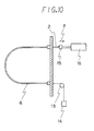
- the measuring method of the characteristic of the operating feeling is shown in Fig. 10.
- the inner cable applied with silicone grease had a length of 1000 mm, and the inner cable 2 was inserted into the conduit 6 having a length of 700 mm.
- control cable 1 was arranged such that a control cable 1 was curved for 180° with a radius of 100 mm in U-like shape.
- a weight 14 of 5 kg is hung through a roller 13, and at the input end of the inner cable, a lineared motor 16 with a load cell 15, which was the load detector, was connected.
- the inner cable 2 was pulled in the direction of an arrow e by means of the lineared motor, such that the velocity was 5 mm/sec and the stroke was 30 mm.
- the sliding motion was repeated ten times, and thereafter, a real pull test was performed.
- the behavior of the slide motion was recorded on an X-Y recorder connected to a load cell 15 (not shown).
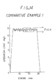
- the difference between the maximum operating force and the minimum operating force, during the pull motion of the inner cable is determined as a characteristic of the operating feeling value F.
- the slipping-out-strength should not be less than 2 kgf in order to securely fix the liner to the outer spring, when another thermoplastic resin is molded at the end face of a conduit for the secondary processing.
- the slipping-out-strength of the liner of Examples 1 and 2 having the above-mentioned foamed material as an interposition are 13 and 16 kgf, respectively.
- the slipping out strength of the comparative Example 1 having the same clearance of -0.3 mm as Examples 1 and 2 is 10 kgf. Therefore, the strength of the Comparative Example 1 is inferior to that of Examples 1 and 2.
- Examples 1 and 2 are 0.1 and 0.2 kgf, respectively.
- Comparative Example 1 is 0.4 kgf. Therefore, the characteristic of the operating feeling of Comparative Example 1 is inferior to that of Examples 1 and 2.
- Comparative Example 2 when the clearance B is made to 0.1 mm in order to make the characteristic of the operative feeling be 0.1 kgf, the slipping-out-strength of liner becomes merely 2 kgf.
- the slipping-out-strength of the liner of Examples 3 to 6 having an above-mentioned low melting material as an interposition is 4.0 to 7.0 kgf.
- the slipping-out-strength of Comparative Example 4 having the same clearance as Example 4 has a strength of 2.0 kgf. That is to say, the strength of Comparative Example 4 is inferior to that of Examples 3 to 6.
- Examples 3 to 6 and Comparative Example 4 are 0.1 kgf, respectively.
- Comparative Example 4 is 0.2 kgf. That is to say, the characteristic of the operating feeling is inferior to that of Example 3 to 6.
- the slipping-out-strength of the liner of Examples 7 to 13 having the above-mentioned string-like member as an interposition is in the range of 4.0 to 8.0 kgf.
- the slipping-out-strength of Comparative Example 4 having the same clearance of 0.1 mm as Example 7 to 13 was merely 2.0 kgf. That is to say, the strength of Comparative Example 4 is inferior to that of Examples 7 to 13.
- Examples 7 to 13 are 0.1 to 0.12 kgf. However, in the Comparative Example 4, the feeling is 0.1 kgf. Therefore, it can be understood that the characteristic of the operating feeling of Comparative Example 4 is nearly equal to that of Example 7 to 13.
- the characteristic of operating feeling is good and the slipping-out-strength can be sufficiently retained, and it can be understood that those effect obtained since in the control cables of Example 1 to 13, the interpositions are interposed between the outer spring 4 and the liner 3, the liner is not hindered from thermal expansion by the outer spring when the control cable is heated, and therefore, the liner is prevented from shrinking when the control cable is cooled, and further since the roughness and the unevenness do not come out on the liner 4 in Examples.
- the control cable of the present invention is able to be prevented from shrink of a liner when the control cable is cooled, since the thermal expansion of a liner is not hindered by an outer spring when the control cable is heated.
- the operating feeling of the control cable of the present invention is good in comparison with conventional control cables.
Applications Claiming Priority (6)
| Application Number | Priority Date | Filing Date | Title |
|---|---|---|---|
| JP101497/89 | 1989-08-30 | ||
| JP1989101498U JP2563435Y2 (ja) | 1989-08-30 | 1989-08-30 | コントロールケーブル |
| JP101496/89 | 1989-08-30 | ||
| JP101498/89 | 1989-08-30 | ||
| JP10149689U JPH0388015U (de) | 1989-08-30 | 1989-08-30 | |
| JP1989101497U JP2563434Y2 (ja) | 1989-08-30 | 1989-08-30 | コントロールケーブル |
Publications (3)
| Publication Number | Publication Date |
|---|---|
| EP0415333A2 true EP0415333A2 (de) | 1991-03-06 |
| EP0415333A3 EP0415333A3 (en) | 1991-11-21 |
| EP0415333B1 EP0415333B1 (de) | 1994-05-11 |
Family
ID=27309478
Family Applications (1)
| Application Number | Title | Priority Date | Filing Date |
|---|---|---|---|
| EP19900116419 Expired - Lifetime EP0415333B1 (de) | 1989-08-30 | 1990-08-28 | Steuerseil |
Country Status (2)
| Country | Link |
|---|---|
| EP (1) | EP0415333B1 (de) |
| DE (1) | DE69008796T2 (de) |
Cited By (5)
| Publication number | Priority date | Publication date | Assignee | Title |
|---|---|---|---|---|
| EP0681113A2 (de) * | 1994-04-07 | 1995-11-08 | Imo Industries Inc. | Bowdenzug und dynamische Dichtung |
| EP2314330A1 (de) * | 2009-10-23 | 2011-04-27 | ECP Entwicklungsgesellschaft mbH | Flexible Wellenanordnung |
| CN105452687A (zh) * | 2013-08-09 | 2016-03-30 | 日本发条株式会社 | 控制电缆用外壳及其制造方法以及控制电缆 |
| CN109424617A (zh) * | 2017-08-25 | 2019-03-05 | 利达工业有限公司 | 一种自行车内线结构 |
| EP2714986B1 (de) * | 2011-05-27 | 2019-09-18 | Setic SAS | Drahtführung und fliegerbügel mit dieser drahtführung |
Families Citing this family (3)
| Publication number | Priority date | Publication date | Assignee | Title |
|---|---|---|---|---|
| DE10324717B4 (de) * | 2003-05-30 | 2014-02-20 | Audi Ag | Biegsames Antriebskabel und Verfahren zur Herstellung eines biegsamen Antriebskabels |
| DE102010042009A1 (de) * | 2010-10-05 | 2012-04-05 | Bos Gmbh & Co. Kg | Rollosystem |
| DE102013210470B4 (de) * | 2013-06-05 | 2017-11-02 | Bos Gmbh & Co. Kg | Antriebsübertragungssystem und Verfahren zur Montage eines derartigen Antriebsübertragungssystems |
Citations (6)
| Publication number | Priority date | Publication date | Assignee | Title |
|---|---|---|---|---|
| US3013443A (en) * | 1959-09-25 | 1961-12-19 | John F Morse | Push-pull cable casing |
| US4099425A (en) * | 1976-06-01 | 1978-07-11 | Samuel Moore And Company | Method of making push-pull cable conduit and product |
| DE8016037U1 (de) * | 1980-09-18 | Kuester & Co Gmbh, 6332 Ehringshausen | Führungsschlauch für Bowdenzüge | |
| DE3021533A1 (de) * | 1980-06-07 | 1981-12-17 | Max Kammerer Gmbh, 6370 Oberursel | Bowdenzug |
| US4378712A (en) * | 1979-02-27 | 1983-04-05 | Nippon Cable System, Inc. | Control cable |
| JPS63219908A (ja) * | 1987-03-09 | 1988-09-13 | Honda Motor Co Ltd | コントロ−ルケ−ブル |
-
1990
- 1990-08-28 DE DE1990608796 patent/DE69008796T2/de not_active Expired - Fee Related
- 1990-08-28 EP EP19900116419 patent/EP0415333B1/de not_active Expired - Lifetime
Patent Citations (6)
| Publication number | Priority date | Publication date | Assignee | Title |
|---|---|---|---|---|
| DE8016037U1 (de) * | 1980-09-18 | Kuester & Co Gmbh, 6332 Ehringshausen | Führungsschlauch für Bowdenzüge | |
| US3013443A (en) * | 1959-09-25 | 1961-12-19 | John F Morse | Push-pull cable casing |
| US4099425A (en) * | 1976-06-01 | 1978-07-11 | Samuel Moore And Company | Method of making push-pull cable conduit and product |
| US4378712A (en) * | 1979-02-27 | 1983-04-05 | Nippon Cable System, Inc. | Control cable |
| DE3021533A1 (de) * | 1980-06-07 | 1981-12-17 | Max Kammerer Gmbh, 6370 Oberursel | Bowdenzug |
| JPS63219908A (ja) * | 1987-03-09 | 1988-09-13 | Honda Motor Co Ltd | コントロ−ルケ−ブル |
Non-Patent Citations (1)
| Title |
|---|
| PATENT ABSTRACTS OF JAPAN vol. 13, no. 10 (M-782)(3358), 11 January 1989; & JP - A - 63219908 (HONDA MOTOR LTD.) 13.09.1988 * |
Cited By (9)
| Publication number | Priority date | Publication date | Assignee | Title |
|---|---|---|---|---|
| EP0681113A2 (de) * | 1994-04-07 | 1995-11-08 | Imo Industries Inc. | Bowdenzug und dynamische Dichtung |
| EP0681113A3 (de) * | 1994-04-07 | 1996-10-09 | Imo Ind Inc | Bowdenzug und dynamische Dichtung. |
| EP2314330A1 (de) * | 2009-10-23 | 2011-04-27 | ECP Entwicklungsgesellschaft mbH | Flexible Wellenanordnung |
| WO2011047883A1 (en) * | 2009-10-23 | 2011-04-28 | Ecp Entwicklungsgesellschaft Mbh | Flexible shaft arrangement |
| US8932141B2 (en) | 2009-10-23 | 2015-01-13 | Ecp Entwicklungsgesellschaft Mbh | Flexible shaft arrangement |
| DE112010003816B4 (de) | 2009-10-23 | 2024-04-11 | Ecp Entwicklungsgesellschaft Mbh | Blutpumpenanordnung |
| EP2714986B1 (de) * | 2011-05-27 | 2019-09-18 | Setic SAS | Drahtführung und fliegerbügel mit dieser drahtführung |
| CN105452687A (zh) * | 2013-08-09 | 2016-03-30 | 日本发条株式会社 | 控制电缆用外壳及其制造方法以及控制电缆 |
| CN109424617A (zh) * | 2017-08-25 | 2019-03-05 | 利达工业有限公司 | 一种自行车内线结构 |
Also Published As
| Publication number | Publication date |
|---|---|
| EP0415333A3 (en) | 1991-11-21 |
| DE69008796D1 (de) | 1994-06-16 |
| EP0415333B1 (de) | 1994-05-11 |
| DE69008796T2 (de) | 1994-12-22 |
Similar Documents
| Publication | Publication Date | Title |
|---|---|---|
| US5245887A (en) | Control cable | |
| US4381140A (en) | Optical fiber cable | |
| US3604461A (en) | Composite tubing | |
| US3866632A (en) | Reinforced hose and method | |
| US5894865A (en) | Flexible hose construction and method of making the same | |
| CA1079161A (en) | Method of making push-pull cable conduit and product | |
| US4259991A (en) | High pressure hose construction and method of and apparatus for making the same | |
| US5621842A (en) | Optical fiber cable and device for manufacturing a cable of this kind | |
| US5636551A (en) | Method of making a mechanical cable | |
| US4273160A (en) | High pressure hose | |
| EP0415333B1 (de) | Steuerseil | |
| KR102050361B1 (ko) | 광섬유 케이블 | |
| US7559189B2 (en) | Soundproof geared cable | |
| EP0291639A1 (de) | Thermoplastisches Verbundrohr mit harzreichem Innenteil und Verfahren zu seiner Herstellung | |
| US4951523A (en) | Control cable | |
| US3543805A (en) | Composite tubing | |
| US3302479A (en) | Low load flexible conduit | |
| US3434501A (en) | Motion transmitting remote control assembly | |
| JP2002039152A (ja) | 樹脂線入りのアウターケーシング、インナーケーブルおよびそれらを組み合わせたコントロールケーブル | |
| JP2563435Y2 (ja) | コントロールケーブル | |
| US3395591A (en) | Remote control assembly construction | |
| US2968321A (en) | Reinforced flexible hose | |
| JP4347441B2 (ja) | コントロールケーブルの内索 | |
| CA2146420C (en) | Lubricous flexible synthetic hose and method for producing same | |
| EP0298524A2 (de) | Vorspannstahlmaterial |
Legal Events
| Date | Code | Title | Description |
|---|---|---|---|
| PUAI | Public reference made under article 153(3) epc to a published international application that has entered the european phase |
Free format text: ORIGINAL CODE: 0009012 |
|
| AK | Designated contracting states |
Kind code of ref document: A2 Designated state(s): DE FR GB IT |
|
| PUAL | Search report despatched |
Free format text: ORIGINAL CODE: 0009013 |
|
| AK | Designated contracting states |
Kind code of ref document: A3 Designated state(s): DE FR GB IT |
|
| 17P | Request for examination filed |
Effective date: 19911217 |
|
| 17Q | First examination report despatched |
Effective date: 19921211 |
|
| GRAA | (expected) grant |
Free format text: ORIGINAL CODE: 0009210 |
|
| ITF | It: translation for a ep patent filed |
Owner name: BARZANO' E ZANARDO MILANO S.P.A. |
|
| AK | Designated contracting states |
Kind code of ref document: B1 Designated state(s): DE FR GB IT |
|
| REF | Corresponds to: |
Ref document number: 69008796 Country of ref document: DE Date of ref document: 19940616 |
|
| ET | Fr: translation filed | ||
| PLBE | No opposition filed within time limit |
Free format text: ORIGINAL CODE: 0009261 |
|
| STAA | Information on the status of an ep patent application or granted ep patent |
Free format text: STATUS: NO OPPOSITION FILED WITHIN TIME LIMIT |
|
| 26N | No opposition filed | ||
| PGFP | Annual fee paid to national office [announced via postgrant information from national office to epo] |
Ref country code: FR Payment date: 19960830 Year of fee payment: 7 |
|
| PGFP | Annual fee paid to national office [announced via postgrant information from national office to epo] |
Ref country code: GB Payment date: 19960906 Year of fee payment: 7 |
|
| PGFP | Annual fee paid to national office [announced via postgrant information from national office to epo] |
Ref country code: DE Payment date: 19960912 Year of fee payment: 7 |
|
| PG25 | Lapsed in a contracting state [announced via postgrant information from national office to epo] |
Ref country code: GB Free format text: LAPSE BECAUSE OF NON-PAYMENT OF DUE FEES Effective date: 19970828 |
|
| GBPC | Gb: european patent ceased through non-payment of renewal fee |
Effective date: 19970828 |
|
| PG25 | Lapsed in a contracting state [announced via postgrant information from national office to epo] |
Ref country code: FR Free format text: LAPSE BECAUSE OF NON-PAYMENT OF DUE FEES Effective date: 19980430 |
|
| PG25 | Lapsed in a contracting state [announced via postgrant information from national office to epo] |
Ref country code: DE Free format text: LAPSE BECAUSE OF NON-PAYMENT OF DUE FEES Effective date: 19980501 |
|
| REG | Reference to a national code |
Ref country code: FR Ref legal event code: ST |
|
| PG25 | Lapsed in a contracting state [announced via postgrant information from national office to epo] |
Ref country code: IT Free format text: LAPSE BECAUSE OF NON-PAYMENT OF DUE FEES;WARNING: LAPSES OF ITALIAN PATENTS WITH EFFECTIVE DATE BEFORE 2007 MAY HAVE OCCURRED AT ANY TIME BEFORE 2007. THE CORRECT EFFECTIVE DATE MAY BE DIFFERENT FROM THE ONE RECORDED. Effective date: 20050828 |